EP1843295B1 - Verfahren zur Wiedergabe von Bewegungen der Visierlinie eines optischen Instruments - Google Patents
Verfahren zur Wiedergabe von Bewegungen der Visierlinie eines optischen Instruments Download PDFInfo
- Publication number
- EP1843295B1 EP1843295B1 EP07290386.7A EP07290386A EP1843295B1 EP 1843295 B1 EP1843295 B1 EP 1843295B1 EP 07290386 A EP07290386 A EP 07290386A EP 1843295 B1 EP1843295 B1 EP 1843295B1
- Authority
- EP
- European Patent Office
- Prior art keywords
- sight
- images
- line
- instrument
- image
- Prior art date
- Legal status (The legal status is an assumption and is not a legal conclusion. Google has not performed a legal analysis and makes no representation as to the accuracy of the status listed.)
- Active
Links
Images




Classifications
-
- G—PHYSICS
- G01—MEASURING; TESTING
- G01C—MEASURING DISTANCES, LEVELS OR BEARINGS; SURVEYING; NAVIGATION; GYROSCOPIC INSTRUMENTS; PHOTOGRAMMETRY OR VIDEOGRAMMETRY
- G01C11/00—Photogrammetry or videogrammetry, e.g. stereogrammetry; Photographic surveying
- G01C11/04—Interpretation of pictures
- G01C11/06—Interpretation of pictures by comparison of two or more pictures of the same area
Definitions
- the invention relates to the field of the exploitation of a sequence of successive images provided by an optical observation instrument mounted on a carrier animated with a movement such that the successive images represent a band of a scene observed, with a recovery between images.
- the invention finds a particularly important, although not exclusive, application in the non-real-time operation of the images provided by an earth observation instrument carried by a moving satellite or aircraft following a substantially known trajectory.
- the rendering of the orientation at each shot relative to a reference mark is in particular required to have good performance in the case of satellites using a camera in the visible range / IR.
- the instrument For each shot, the instrument will be oriented and stabilized in a given direction, possibly with a small residual rotation speed controlled by the user. During the shooting, the information delivered by the detector-bars will be stored, then retransmitted and processed on the ground in order to reconstitute two-dimensional images of the observed zones.
- the determination of the orientation and the angular movements of the line of sight at any moment during the shots is carried out thanks to the use of angular position and speed sensors, such as sensors.
- angular position and speed sensors such as sensors.
- stellar and gyroscopes the increase in the resolution of the instruments requires a restitution of attitude more and more precise, difficult to achieve with such sensors.
- the star sensors provide a very high attitude measurement accuracy, but in a relatively low frequency range (typically less than a few Hertz).
- Gyroscopes are also limited in bandwidth (typically less than a few tens of Hertz), often because of their electronics.
- these two types of sensors do not provide a direct measure of the line of sight of the instrument since by nature they only provide information on their own orientation.
- the document FR2 828 314 discloses a method of electronically stabilizing images of a scene of a state-of-the-art camera, in which images of the scene are filtered to retain only low spatial frequencies.
- the present invention aims to provide a method and a device for measuring and restoring the movements of the line of sight of an optical instrument and the orientation of the line of sight at each shot relative to an initial reference, and this without necessarily using the measurements of external sensors of position and angular velocity, but rather by directly using the images taken by the instrument itself.
- characteristic zone for example a portion of the scene typically of a few hundred pixels which contains radiometric information (luminance and / or chrominance), geometric or textural making it suitable for matching.
- "Characteristic point” means a point whose immediate vicinity is a characteristic zone in the preceding sense. In practice, this leads to the use, as characteristic zones, of locations in which the second-order local derivatives of the radiometry are non-zero in two distinct directions.
- the step (a) may implement a mapping of characteristic image areas based on a geometric, radiometric or textural similarity between at least two images acquired during the shooting.
- the method as defined above makes it possible to obtain a relative restitution of the orientation of the aim, with respect to an initial reference point; this relative restitution is sufficient to meet the usual needs, that is to say, the provision of information making it possible to take into account the alteration of the lengths, to superimpose spectral bands, to take into account the altimetry and superimpose images from several sensors of the sensitive instrument in different spectral bands.
- the method is based on the mapping of points or areas of the image that can be: characteristics (in the sense previously stated), pre-determined independently of the image in the vicinity with or without prior knowledge of particular elements present in the scene, selected in a subset of points or characteristic areas.
- the matched images are taken in spectral bands that may be the same or different.
- the quality of matching (for example based on correlation measurement) is an important criterion in the step of resetting the geometric model.
- the mapping step can be implemented by conventional registration methods, such as for example that described in the article of KIM SP AND AL: "Subpixel accuracy image registration by spectrum cancellation”; Image and multidimensional signal processing. MINEAPOLIS, APR. 27-30, 1993, PROCEEDINGS OF THE INTERNATIONAL CONFERENCE ON ACOUSTICS, SPEECH, AND SIGNAL PROCESSING (ICASSP), NEW YORK .
- step (b) when a quadratic function of the deviations is used, said differences occurring in the quadratic criterion to be minimized are weighted by a positive scalar proportional to the estimated quality of said mapping of said characteristic zones between the two images, the estimation of said quality of mapping being calculated according to the methods of the state of the art (correlation calculation for example).
- the step of reconstituting the movements of the line of sight on the time horizon [Ti, Tf] consists of integrating, filtering and possibly resampling all the elementary variations reconstructed by resetting the geometric model.
- Reverse filtering can be used to enhance some attenuated frequencies while limiting the impact of noise.
- another approach is to adjust an analytical model, for example estimating the coefficients of a polynomial of degree not exceeding 5 in general by a least squares method.
- This filtering step must overcome a temporary lack of correlation data according to a suitable interpolation technique.
- One can use at this stage a knowledge a priori on the frequency content of the movements of line of sight.
- the orientation of the line of sight at time Tn is advantageously calculated by interpolation of the line of sight orientations reconstituted by the application of the method at times before and after Tn.
- step (c) The a priori knowledge of the frequency content of the variations of the orientation of the line of sight can be used to carry out before step (c) a filtering retaining only the frequencies concerned.
- any pair of images provides motion information that can be merged together.
- the merger can be iterative in which case the order of the iterations intervenes in the final performance. Iterations can be chained until data exhaustion or process convergence. Couplings of higher correlation images provide more accurate and robust motion information that can, if necessary, correct the line of sight movements of an image whose content is less strongly correlated.
- the method can be applied to several pairs of images and the results obtained from the different pairs of image images are hybridized. the same scene by implementing a global or iterative refinement of the current knowledge of the orientation of the line of sight during the shooting.
- the method can be applied to a first pair of images advantageously among the pairs of images supposed to be the best correlated, for example those taken in the same spectral band, in order to obtain a first reconstitution of the movements of the line during the shooting, then another pair of images is processed by initializing the mapping model from the values of the line of sight orientation calculated in the previous step , and so on until data is exhausted or convergence is achieved.
- the instrument makes it possible to form at least three images shifted in time, at least two of the images having a strong correlation between them, and at least one other image weakly correlated with the other two, and the movements of line of sight on at least one image weakly correlated with the other two through the reconstitution of said movements of the line of sight performed by applying the method to at least one pair of images having a strong correlation between them.
- the initialization of the mapping model can be performed with a priori knowledge of the orientation of the line of sight during shooting.
- This prior knowledge can be derived from an orientation instruction or a measurement derived from attitude sensors such as stellar sensors, gyrometers, etc., or from a knowledge of the absolute position on the Earth's surface of the Earth. recognizable characteristic areas in the image, or a hybridization of such knowledge.
- the parallax effects can be taken into account in the matching model, using a priori knowledge of the relief of the observed scenes.
- the satellite may also be placed in a moving orbit, but the satellite orbit may also be geostationary.
- the camera may comprise, in its focal plane, at least two bar-type detectors, the bars being aligned so that their lines and columns are respectively substantially parallel, and the two bars of each pair of bars, of which at least one pair is thus in the focal plane, being separated from each other by a distance of typically a few fractions of mm to a few mm in the focal plane, the detectors thus observing approximately the same portion of the scene during a shooting, with a temporal shift directly dependent on the distance between the detectors at the focal plane.
- each line of the detectors of the focal plane can form an image of the scene, and a subset of the images thus created by all the detectors of the focal plane can be processed according to the method of the invention to reproduce the image. orientation of the line of sight of the instrument.
- the instrument comprises at least one main sensor of the bar type in its focal plane, this detector being used to ensure the image taking according to the desired mission characteristics (swath width, resolution, image quality, etc.), is added in the focal plane for application of the method according to the invention and as defined above, at least one dedicated detector, of smaller size, typically a matrix of 100x100 pixels, or a bar of 1000x10 pixels, and said dedicated detector is placed at a certain distance from said main detector and the method according to the invention is applied.
- the desired mission characteristics thin width, resolution, image quality, etc.
- At least two aligned and spaced array type main detectors, or at least one main detector of the bar type and a dedicated detector spaced apart from each other are arranged in the focal plane of the instrument, the separation of the detectors in this focal plane can be optimized for the reconstruction of the movements of the line of sight in a given frequency band.
- said instrument comprises only one detector in the focal plane, scanning the scene, and the method according to the invention and as defined above is applied to at least two images formed from at least two lines of the detector.
- the choice of the at least two lines of the detector used to form the at least two images can be optimized for the reconstruction of the movements of the line of sight in a given frequency band.
- the orientation of the line of sight by image processing can be used in a process of optimizing the image quality provided by the instrument with regard to the alteration of the lengths, the planimetric restitution, the altimetric restitution, the superposition of images from multiple sensors and / or formed at different times.
- the method also makes it possible to measure micro-vibrations of the instrument in the limit where their frequency does not exceed those recoverable by the method.
- the figure 1 which is a simple diagram where the scale is not respected, shows a satellite 10 whose platform carries an instrument 12 having in its focal plane a matrix detector in two dimensions, controlled so that two successive images, for example 14a and 14b, taken at times separated by a time interval T, have a noticeable overlap, which will generally be at least half of the image.
- Each image is constituted by a matrix of pixels, grouped in lines (perpendicular to the direction of displacement) and columns (parallel to the direction of displacement).
- a sensor apparatus constituted by a bar, operating on the so-called "push-broom" principle, the bar is oriented in the direction of the lines of the image to be obtained.
- the platform of the satellite 10, and consequently the instrument, are likely to present movements around the three axes x (roll), y (pitch) and z (yaw). All these movements lead to variations in the orientation of the line of sight V.
- the apparatus may comprise two detectors separated in the field in the scanning direction, resulting in an average time interval T between the acquisition of a point by one of the detectors and the acquisition of the same point by the other detector.
- the figure 2 shows an offset between two successive images caused by a roll motion ⁇ x (around the x axis).
- images 14a and 14b have a relative arrangement of the kind shown at 14a and 14b, i.e., a shift in the direction of the lines.
- a pitch orientation change leads, in the first order, to an additional shift of the image in the direction of the columns of pixels, constant over the entire width of the field, equal to k.
- ⁇ y ( ⁇ y being the orientation variation around the pitch axis and k being a constant).
- a variation ⁇ z around the yaw axis results in a rotation of the image which essentially causes a change of position in the direction of the columns of pixels, variable over the width of the field.
- an error in the positioning of the line of sight in yaw translates to the first order by a shift of the image in the direction of the lines, constant over the width of the field, which generally can not be decorrelated from that caused by a variation of roll.
- the process according to the invention can be considered as comprising three successive stages, indicated on the figure 4 .
- the first step consists of an image processing intended to match the different available images (at least two for the same portion), having acquired the same portion of the zone at different times, by exploiting their radiometric, geometrical resemblance. or textural.
- the second step consists in deducing, from the identification of several pairs of homologous points, over a short duration, the information of angular variation around the three axes x, y and z, taking into account a geometrical model of the device, defined later, and refining it.
- Two pairs of homologous points in two images allow in principle to determine the variations. But the use of more than two couples makes it possible to filter on the correlation noise and also on the errors related to the relief of the observed scene, caused in particular by the parallax.
- the third step consists of an integration of the measurements to go back to an estimate of the attitude at each shot, compared to an initial reference point.
- This marker can only be relative if the image processing is used alone. It can be made absolute by a periodic resetting from an absolute restitution of attitude in an inertial frame with additional sensors, such as gyros or especially stellar sensors.
- the various steps of the method can be carried out by a computing device constituted for example by a data acquisition and preprocessing chain, a main processing chain including hardware (microprocessor, FPGA, ASIC) and software, the assembly for performing the processing steps according to the method, the implementation of these software providing the desired digital variables, that is to say in particular the angles and rotational speeds of the line of sight of the instrument in question.
- a computing device constituted for example by a data acquisition and preprocessing chain, a main processing chain including hardware (microprocessor, FPGA, ASIC) and software, the assembly for performing the processing steps according to the method, the implementation of these software providing the desired digital variables, that is to say in particular the angles and rotational speeds of the line of sight of the instrument in question.
- the mapping will often be performed during step a) from images obtained in different spectral bands, as long as a correlation is likely to be made. But some spectral bands correlate poorly with each other, because they have different radiometric contents. This is for example the case between the PIR band and the bands in the visible. In this case, the restitution obtained by comparison of the images in the panchromatic bands and XS (or between two bands in the visible) makes it possible to then apply the restitution of images to the PIR band; more generally, the restitution makes it possible to superimpose images in different spectral bands of the instrument having a low radiometric correlation.
- the determination of the alteration of the lengths can notably be carried out starting from the mapping between pixels PAN and XS.
- the determination of the relative attitude from the image processing has the advantage of giving a linear information, which can be integrated in time to adapt the measurement carried out to the required duration (or "horizon"), generally of several seconds.
- This approach is much more favorable than the use of gyroscopes, which require a long integration of measurements and cause an accumulation of errors.
- the mapping between the panchromatic pixels and XS makes it possible in particular to use an important time interval and thus to limit the amplitude of the integration errors.
- the second step of the method implements a geometric modeling of matching shots.
- the image matching can be performed by known filtering techniques, Fourier transform, wavelet decomposition.
- the method uses a determination of a certain number of characteristic points, identified as having high radiometric variation neighborhoods (typically second derivative with respect to the distance greater than a threshold in at least two different directions) and search for homologous points of points characteristics in at least one other image by exploiting similarities. It is desirable to use more than two pairs of points, to account for possible mapping errors that may have different origins, such as the radiometric quality of the images, the geometric quality of the images, and the spectral content of the images.
- the currently available registration techniques make it possible to obtain, in the case of very similar images, a resolution of up to 0.01 pixel for images corresponding to identical spectral bands and 0.1 pixel. for matching images in two different spectral bands.
- mapping of the images will make it possible, for the common portion of two successive images, to determine pairs of homologous points, as indicated, for example, schematically in the images 1 and 2 of FIG. figure 5 .
- the geometric modeling of the optical system makes it possible to associate at any point of an image, such as the point A1 of the image 1, a corresponding position P in the observed scene and, conversely, the inverse model associates with any point of the scene, for example at point P, the corresponding point A1 or A2 in image 1 or 2.
- Loc ⁇ 1 the function which associates, with any pixel of the image 1, an estimation of the coordinates on the ground of the corresponding point P.
- Loc ⁇ 1 M i j P where i and j correspond to the row and column location.
- ⁇ 1 represents the set of parameters of the geometric model associated with the image 1. These parameters may include the attitude of the aiming mark, the position of the satellite, the dating of the parameters, the geometric modeling of the instrument (direction of aim of each of the detectors in the sighting mark) and the altitude of the points observed.
- H the image correlation function which, at a point M1 of the image 1, correlates by correlation its counterpart M2 in the image 2.
- H M 1 i 1 j 1 M 2 i 2 j 2
- H is affected by the image matching error and Loc ⁇ 1 / ⁇ 2 is affected by the uncertainty about the knowledge of the model parameters, and in particular, the attitude of the aiming point.
- Res ⁇ 1 / ⁇ 2 the residual function which, for every point of the image 1, associates the difference between the point M2 of the image 2 obtained by the function H and the point M'2 obtained by Loc ⁇ 1 / ⁇ 2 .
- the measured residual designated Res la 1 / ⁇ 2 , incorporates the errors listed above, plus the attitude variation errors that are to be measured.
- the method will generally use a first-order linear modeling and an approximation of the first-order model.
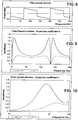
- Wiener's theory leads to the definition of an optimal filter in the sense of minimizing the mean squared error.
- H k BOY WUT ⁇ BOY WUT 2 + k
- H k ⁇ e - j ⁇ - 1 2. 2 - cos ⁇ + k
- the gain of the chain is: 3
- the Wiener filter cuts all the harmonics of frequency nf ⁇ . because at these frequencies, there is no signal.
- the inverse filter tends to diverge, despite the choice made for k, whose Figures 9 and 10 show the effect with the same other parameters as on the figures 7 and 8 .
- a significant value of k corresponds to a measurement noise level of the significant angular variation with respect to the signal level (initial error on the knowledge of this variation). Data filtering is stronger and break bands are wider.
- the increase in k also decreases the gain of the complete processing chain.
- the time constant is 1OxTe, which is a cutoff at 1 / (10.Te) Hz.
- the differentiation over a time interval ⁇ introduces narrower bands between which the signal is cut off.
- a compromise or combination is necessary. Indeed, a high value of ⁇ makes it possible to go down in frequency, but with narrow bands. On the other hand, a low value of ⁇ gives broad bands, but does not make it possible to reproduce the low frequencies.
- the releasable band can then be defined by the maximum value of the elementary bands.
- the figure 13 shows how the combination of available image pairs can restore the signal in a wide band.
- the direction of the columns is also a temporal dimension.
- the matching is performed on a two-dimensional area (vignette) in the vicinity of a point. It contains the movements of the line of sight during the duration of its acquisition. Correlation operates as a filtering on the signal that we are trying to measure. This problem does not exist in the case of matrix detectors.
- mapping As far as mapping is concerned, conceivable algorithms include image correlation, filtering, Fourier transform approaches or wavelet decomposition.
- the mapping between the images makes it possible to obtain a certain number of pairs of homologous points, defined on an essentially radiometric criterion.
- the geometric modeling of the system makes it possible to obtain a prediction of these homologous points.
- the residual (differences between the predicted point and the correlated point) corresponds to the errors of knowledge of these parameters, as well as approximations made by the model. Estimating attitude variations requires separating these contributions from other items (instrument model, parallax, etc.).
- the treatment can be performed at each homologous point, or globally over the entire width of the field.
- the second solution has the advantage on the one hand, to operate a certain filtering on the measurements, and on the other hand, to take advantage of the invariants of the image relating to the rigidity of the focal plane and to the fact that the motion the aiming mark is the same whatever the point of the field is considered.
- a least-squares estimation type calculation can be used as an instantaneous estimate of attitude variation.
- mapping provides the "absolute" pixel coordinates of the points in one image, as well as the coordinates of the peer points in the other image. This correspondence is difficult to exploit if we do not have references.
- a reference can be calculated by point prediction using the best geometric knowledge of the system. The residue is then the gap between the two points. It includes all errors related to this knowledge, except known geometric effects.
- the effects related to the lack of awareness of the absolute orientation are small (but often significant) compared to the effects of movement.
- This absolute orientation is not directly observable, because its effects merge with those related to movement.
- the sensitivity is very low.
- the sensitivity coefficients can be calculated numerically at each point of the focal plane, and at each moment, using the best knowledge of the system available.
- Two homologous points are calculated in the image 2 corresponding to the same point in the image 1, by slightly varying one of the parameters. ⁇ di ⁇ ⁇ M 1 ⁇ i ' 2 - i 2 d ⁇ ⁇ dj ⁇ ⁇ M 1 ⁇ j ' 2 - j 2 d ⁇
- the first is to refine the attitude profile restored in a conventional manner, which is given an error model, by estimating the parameters of this error model.
- the second approach is to take the set of valid attitude measurements from the various sensors, when available, and to redo a complete estimate on the ground, this time associating the image measurements.
- it is a problem of signal processing for which we have algorithms such as Wiener filtering or statistics, the least squares method, etc, ). Examples will now be described.
- the analysis of the effect of k shows that the performance of the filter passes through an optimum for a given value of k. If k is too weak, the measurement noise is too strongly amplified. If k is too strong, the signal to be restored is too filtered. Theoretically the value of optimal k is 1 / RSB 2 , in the case of two white noises. In practice, the signals (useful signal and error signal) are much more complex than simple white noise. If Wiener's approach is adopted for the restitution, the coefficient can be optimized from simulations.
- ⁇ e the sampling frequency
- ⁇ ( ⁇ ⁇ c ) 1 for ⁇ ⁇ c , and is zero elsewhere.
- the least squares method by estimating the parameters of a polynomial model of the signal, makes it possible better to treat the low frequencies.
- the continuous component is not restorable.
- ⁇ i ⁇ mes (t i ) for i between 1 and k1.
- ⁇ i ⁇ (t i ) T.
- ⁇ ⁇ 1 , ⁇ 2 , ... , ⁇ k
- ⁇ M ⁇ . ⁇ + B
- ⁇ M ⁇ T . ⁇ my - 1 . M ⁇ - 1 , M ⁇ T . ⁇ my - 1 . ⁇
- ⁇ mes is the covariance matrix E (BB T )
- a gain of around 1 achieves an attitude-restoring performance similar to the performance of measuring initial angular variations. We will try to keep this gain systematically less than 10, if we make the analogy between the image correlation error (typically, 0.1 pixel) and the acceptable attitude recovery error (typically 1 pixel).
- the error is practically only sensitive to time parameters, deviation ⁇ , sampling step Te and restitution horizon n.Te (n being the number of measurements).
- ⁇ can not exceed or even approach the observation time, because there is no further matching images possible.
- the step 20 of selecting the points to be correlated constitutes the start of iteration. It can include a mechanism for rejecting false homologous points (from the previous iteration), to increase the robustness of the processing matching errors.
- the process is initialized by an initial estimate, consisting of the best knowledge of the aiming orientation available. This knowledge can be derived from gyro measurements, measurements provided by a star sensor, the shooting instruction, or any hybridization of this information.
- the prediction of the homologous points of one image with respect to the other is carried out in step 22 by an inverse location / location algorithm which may be that described above under the heading "localization model in the image" .
- This prediction takes into account memorized indications, such as the instrument model, the orbit characteristics, a digital elevation model of the observed terrain.
- the matching of the point-to-point images in step 24 is performed by any type of matching algorithm exploiting the radiometric resemblance between images.
- the initialization of this mapping, limiting the search area of the homologous points, can be provided by the knowledge of the predicted points at 22.
- the size of the search area is then determined by the accuracy of the predictor.
- the residues are provided by subtraction at 26.
- the estimation of the angular variations from the residues is carried out in step 28 according to the algorithm given in II-2 "estimation of angular variations".
- step 30 of integration and filtering of the angular measurements is performed according to the algorithms presented under the title II-3 "integration and temporal filtering".
- the processing may be preceded by low pass filtering when the sampling frequency of the measurements is much higher than the frequencies in the line of sight movement, which is often the case.
- Such a filtering makes it possible to smooth the measurements, and to eliminate the high frequency noises which are measurement noise.
- the refined estimate (and possibly the absolute orientation) of the line of sight can be restored from the initial estimate by a subtractor 32, whose output can be looped back to the input of the processing.
- the method described above finds a particularly advantageous application for calculating the orientation of the line of sight V of an on-board optical instrument 12 on board a satellite 10, as already described above, by reference to the figure 1 , for a satellite 10 placed in moving orbit, and provided with a nadir aiming instrument 12, taking images of successive portions of the terrestrial band 16 overflown and observed, thanks to a detection assembly located at the focal plane of the instrument 12 and comprising a two-dimensional matrix detector controlled to take successive image pairs having a noticeable overlap.
- the detection assembly at the focal plane 13 may comprise a single detector 14 of the strip type typically having 1 (but preferably at least 2) to a few tens of lines 15, each comprising from 1000 to 10 000 pixels, for example, the bar operating on the principle called "push-broom" and being oriented in the direction of the lines of the image to be obtained, that is to say that the strip 14 sweeps the scene observed in a direction perpendicular to its lines, the satellite 10 being pointed in such a way that this bar-type detector 14 sweeps the area 16 to be observed when shooting.
- the method according to the invention is then applied to the successive image pairs, as defined above, or, alternatively, this method is applied to at least two images formed from at least two lines, for example 15 1 and 2 , the bar detector 14 of the figure 18 .
- the choice of at least two lines 15 1 and 15 2 used on the strip detector 14 to form the at least two images is optimized for the purpose of reconstituting the movements of the line of sight V in a frequency band given.
- the detection assembly at the focal plane 13 of the satellite 10 in moving orbit of the figure 1 can comprise several main detectors of the bar type, for example three strip detectors 14 1 , 14 2 and 14 3 which are aligned, that is to say whose lines of pixels, from which are formed the images to be processed according to the method above, are parallel to each other from one bar to the other, and thus also the columns, the strip detectors 14 1 , 14 2 and 14 3 being spaced from each other in a direction perpendicular to their lines by spatial differences ⁇ X 1 , between the two detectors 14 1 and 14 2 , ⁇ X 2 , between the two detectors 14 2 and 14 3 , and ⁇ X 3 between the two detectors 14 1 and 14 3 , so as to constitute three pairs of strips, the two bars of each pair are separated from each other by a distance such that ⁇ X 1, ⁇ X 2 or ⁇ X 3 of typically a few fractions of mm to a few mm in the focal plane 13, so that The result
- the strip detectors 14 1 , 14 2 and 14 3 thus observe approximately the same portion of the scene, during a shooting, with a time shift that depends directly on the distance ⁇ X 1 , ⁇ X 2 or ⁇ X 3 between the detectors strips 141, 14 2 and 14 3 in the focal plane 13.
- each line 15 of the strip detectors 14 1 , 14 2 and 14 3 can form an image of the scene, and at least a subset of the images thus created by all the detectors of the focal plane 13 can be processed according to the method of the invention to restore the orientation of the line of sight V of the optical instrument 12.
- the detection assembly at the focal plane 13 of this instrument 12 can be constituted, as schematically represented on the figure 20 , a main detector of the strip type 14, whose number of lines and the number of pixels per line are suitable for the use of this detector 14 to ensure the image taken according to the desired characteristics of a mission, in term, for example, image quality, resolution and / or swath width, and this main detector 14 is associated, in the focal plane 13, for application of the method according to the invention and as defined above.
- the method of the invention can also be applied to the calculation of the orientation of the line of sight V of an optical instrument 12 for taking pictures on a spinned satellite 10, as shown schematically on the figure 16 , whose stabilization is ensured by the rotation on itself, around the axis of its cylindrical platform, so that the line of sight V of the instrument 12 is controlled in such a way that the whole detecting the focal plane 13 of the instrument 12, and which may be an assembly according to one or other of the figures 18 , 19 and 20 , sweeps a surface band 16 of the terrestrial globe 17 thanks to the rotation of the satellite 10.
- the scanning of a strip 16 of the surface of the globe 17 by the detection assembly at the focal plane 13 of the optical instrument 12 on board a carrier satellite 10 can be ensured by scanning an orientable mirror 34, placed on the optical path of the camera 12, the scanning mirror 34 oscillating, about a pivot axis A fixed relative to the platform of the satellite 10, between two extreme positions marked in dotted line, so as to reflect the image of the ground strip 16 on a concave mirror 35 of the instrument 12, this mirror 35 reflecting this image on a convex mirror 36 itself focusing the image on the detection assembly to the point focal point 13, where the detection assembly can be either of the detection sets of the figures 18 , 19 and 20 , i.e.
- the satellite's orbit may be moving or geostationary.
Landscapes
- Engineering & Computer Science (AREA)
- Multimedia (AREA)
- Physics & Mathematics (AREA)
- General Physics & Mathematics (AREA)
- Radar, Positioning & Navigation (AREA)
- Remote Sensing (AREA)
- Image Processing (AREA)
- Image Analysis (AREA)
- Processing Or Creating Images (AREA)
Claims (23)
- Verfahren zur Rekonstruktion von Roll-, Nick- und Gierbewegungen einer Visierlinie (V) eines Beobachtungsinstruments (12) im Verlaufe von Bilderfassungen einer Dauer von typisch einigen Sekunden pro Aufnahme, wobei die Bewegungen jedes Bild in einem Frequenzbereich verformen, der bis zu hohen Frequenzen von einigen hundert Hertz reichen kann,
wobei gemäß dem Verfahren ausgehend von dem an einem verschiebbaren Träger (10) angebrachten Instrument (12) während der Aufnahmezeitdauer [Ti, Tf] mindestens zwei Bilder (14a, 14b), die einen gleichen Abschnitt einer Szene enthalten, erzeugt werden, wobei die Aufnahmen dieser zwei Bilder um einen bekannten Wert T, der im Wesentlichen konstant ist, zeitlich versetzt sind, und die Bewegungen der Visierlinie (V) des Instruments (12) im Verlaufe der Aufnahme durch mindestens die folgenden Schritte bestimmt werden:a) einen Schritt der Auswahl und Korrespondenzsetzung mehrerer charakteristischer homologer Zonen; wobei jede charakteristische Zone ein Szenenabschnitt von einigen hundert Pixeln ist, der radiometrische, geometrische oder strukturelle Informationen enthält, wobei die charakteristischen Zonen jeweils in der Nähe von Zeitpunkten Tn und Tn + T (n = 1 bis N) aufgenommen sind, die zwischen Ti und Tf in den Bildern des gleichen Abschnitts der Szene verteilt sind, um in jedem der zwei Bilder des Abschnitts eine Messung der Position der homologen Zonen oder mindestens eines speziellen Punkts dieser Zonen an den jeweiligen Zeitpunkten Tn und Tn + T (n = 1 bis N) zu gewinnen,b) einen Schritt der Berechnung von Winkeländerungen der Visierlinie (V) des Instruments (12) zwischen den Zeitpunkten Tn und Tn + T (n = 1 bis N) durch Nachjustierung eines Modells der Korrespondenzsetzung der Bilder, wobei das Modell für jeden Punkt eines zum Zeitpunkt Tn (n = 1 bis N) aufgenommenen ersten Bilds eine Schätzung der Position seines homologen Punkts in einem zum Zeitpunkt Tn + T aufgenommenen zweiten Bild als Funktion von Parametern liefert, die insbesondere die Orientierung der Visierlinie (V) des Instruments (12) zum Zeitpunkt Tn und die Winkeländerungen dieser Visierlinie (V) zwischen Tn und Tn + T aufweisen; wobei die Nachjustierung des Modells darin besteht, die Werte der Winkeländerungen zu berechnen, die eine beispielsweise quadratische Funktion der Abstände zwischen der von dem Modell vorhergesagten Position der homologen Zonen des zweiten Bilds und der in Schritt (a) rekonstruierten Position der homologen Zonen des zweiten Bilds minimieren, undc) einen Schritt der Rekonstruktion der Bewegungen der Visierlinie (V) über den Zeithorizont [Ti, Tf] durch Integration, Filterung und gegebenenfalls erneutes Sampling der Gesamtheit der in Schritt (b) rekonstruierten elementaren Veränderungen. - Verfahren nach Anspruch 1, dadurch gekennzeichnet, dass der Schritt (a) eine Korrespondenzsetzung von charakteristischen Bildzonen auf Basis einer geometrischen, radiometrischen oder strukturellen Ähnlichkeit zwischen mindestens zwei bei der Aufnahme erfassten Bildern durchführt.
- Verfahren nach einem der Ansprüche 1 und 2, dadurch gekennzeichnet, dass mindestens eine der folgenden Methoden verwendet wird, um die charakteristischen Zonen, die mit einem gegebenen Aufnahmedatum Tn verknüpft sind, auszuwählen:- Auswahl von Punkten, deren doppelter Gradient größer als eine gegebene Schwelle ist, in einer Zone des Bilds, die einer nahe am Zeitpunkt Tn gemachten Aufnahme entspricht;- Auswahl von Punkten, die vorgegebene Positionen haben, unabhängig des Inhalts des Bilds in der Nachbarschaft dieser Punkte, gegebenenfalls mit Zurückweisen von Punkten, für welche ein Korrespondenzsetzung-Qualitätskriterium kleiner als eine gegebene Schwelle ist;- Auswahl von vorab festgelegten Punkten, die durch eine a priori Kenntnis von in der Szene vorhandenen, besonderen Elementen gegeben ist;- Auswahl einer Untergruppe von Punkten aus einer Gruppe von charakteristischen Punkten, die mit einem der obigen Verfahren oder ähnlichen berechnet werden, derart, um die räumliche Verteilung der Punkte und die Qualität der Korrespondenzsetzung der charakteristischen Zonen in der Nachbarschaft dieser Punkte zu maximieren;- Auswahl eines Felds von typisch einigen zehn bis einigen hundert Pixeln in der Nachbarschaft der Punkte, um die Qualität der Korrespondenzsetzung zu verbessern.
- Verfahren nach einem der Ansprüche 1 bis 3, dadurch gekennzeichnet, dass die in Korrespondenz gesetzten Bilder in Spektralbändern aufgenommen sind, die gleich oder unterschiedlich sein können.
- Verfahren nach einem der vorstehenden Ansprüche, dadurch gekennzeichnet, dass im Schritt (b) die Abstände, die in dem zu minimierenden quadratischen Kriterium auftreten, mit einem positiven skalaren Wert, der proportional zur geschätzten Qualität der Korrespondenzsetzung der charakteristischen Zonen in den zwei Bildern ist, gewichtet werden, wobei die Schätzung der Qualität der Korrespondenzsetzung gemäß den Verfahren des Stands der Technik (zum Beispiel Korrelationsberechnung) berechnet wird.
- Verfahren nach einem der vorstehenden Ansprüche, dadurch gekennzeichnet, dass im Verlaufe des Schritts (c) eine Integration, eine Filterung und gegebenenfalls ein erneutes Sampling der im Schritt (b) ausgegebenen Schätzungen der Fluglageänderung durchgeführt werden, um die Bewegungen der Visierlinie des Instruments, außer Absolutkomponente der Orientierung der Visier, in dem Zeitintervall [Ti, Tf] mit Hilfe mindestens eines der folgenden Verfahren zu rekonstruieren:- durch Verwenden einer inversen Filterung, die erlaubt, gewisse abgeschwächte Frequenzen zu verstärken und zugleich den Einfluss des Rauschens zu begrenzen, zum Beispiel ein Wiener- oder Kaiman-Filter,- durch Anpassen eines analytischen Modells, zum Beispiel Schätzung der Koeffizienten eines Polynoms, dessen Grad im Allgemeinen 5 nicht überschreitet, gemäß einem Verfahren der kleinsten Quadrate.
- Verfahren nach einem der vorstehenden Ansprüche, dadurch gekennzeichnet, dass bei Abwesenheit einer qualitativ ausreichenden Korrespondenz der gewählten charakteristischen Zonen zum Zeitpunkt Tn die Orientierung der Visierlinie zum Zeitpunkt Tn vorteilhaft berechnet wird mittels einer Interpolation der durch Anwendung des Verfahrens rekonstruierten Orientierungen der Visierlinie zu Zeitpunkten vor und nach Tn.
- Verfahren nach Anspruch 6 oder 7, dadurch gekennzeichnet, dass die a priori Kenntnis des Frequenzinhalts der Änderungen der Orientierung der Visierlinie verwendet wird, um vor dem Schritt (c) eine Filterung durchzuführen, die nur die betreffenden Frequenzen zurückhält.
- Verfahren nach einem der vorstehenden Ansprüche, dadurch gekennzeichnet, dass eine Anzahl von Bildern derselben Szene größer gleich zwei verwendet wird, das Verfahren auf mehrere Bildpaare angewendet wird und die mit unterschiedlichen Bildpaaren derselben Szene gewonnenen Ergebnisse kombiniert werden, indem eine allgemeine oder iterative Verfeinerung der laufenden Kenntnis der Orientierung der Visierlinie bei der Aufnahme durchgeführt wird.
- Verfahren nach Anspruch 9, dadurch gekennzeichnet, dass das Verfahren auf ein erstes Bildpaar, vorteilhaft eines von Bildpaaren, von denen vermutet wird, dass sie die am besten korrelierten sind, zum Beispiel die in einem gleichen Spektralband aufgenommenen, angewendet wird, um eine erste Rekonstruktion der Bewegungen der Visierlinie des Instruments während der Aufnahme zu gewinnen, dann ein anderes Bildpaar behandelt wird, indem das Korrespondenzmodell mit den im vorausgehenden Schritt berechneten Werten der Orientierung der Visierlinie initialisiert wird, und so fort, bis alle Daten ausgeschöpft sind oder Konvergenz erreicht ist.
- Verfahren nach Anspruch 10, dadurch gekennzeichnet, dass das Instrument erlaubt, mindestens drei zeitlich versetzte Bilder zu erzeugen, wobei mindestens zwei der Bilder eine starke Korrelation untereinander haben und mindestens ein anderes Bild schwach mit den zwei anderen korreliert ist, und dadurch, dass die Bewegungen der Visierlinie auf mindestens einem schwach mit den zwei anderen korrelierten Bild korrigiert werden mit Hilfe der Rekonstruktion der Bewegungen der Visierlinie, die sich ergibt durch Anwenden des Verfahrens auf mindestens ein Bildpaar, das eine starke Korrelation untereinander hat.
- Verfahren nach einem der vorstehenden Ansprüche, dadurch gekennzeichnet, dass das Modell der Korrespondenzsetzung initialisiert wird mit einer a priori Kenntnis der Orientierung der Visierlinie während der Aufnahme, wobei die a priori Kenntnis resultiert aus: einem Orientierungseinstellwert oder einer Messung, die von Lagesensoren wie Sterndetektoren und Gyrometern stammt, oder einer Kenntnis der absoluten Position von in dem Bild erkennbaren charakteristischen Zonen auf der Erdoberfläche oder einer Kombination dieser Kenntnisse.
- Verfahren nach einem der vorstehenden Ansprüche, dadurch gekennzeichnet, dass in dem Modell der Korrespondenzsetzung Parallaxeneffekte berücksichtigt werden, indem eine a priori Kenntnis des Reliefs der beobachteten Szenen verwendet wird.
- Verfahren nach einem der vorstehenden Ansprüche, in welchem die Bilder mit Hilfe eines Detektors gewonnen werden, der nach dem sogenannten "push-broom"-Prinzip arbeitet.
- Anwendung des Verfahrens nach einem der Ansprüche 1 bis 14 auf die Berechnung der Orientierung der Visierlinie (V) eines optischen Bildaufnahmeinstruments (12), das sich an Bord eines Satelliten (10) befindet, dadurch gekennzeichnet, dass- das Instrument (12) in seiner Fokalebene (13) mindestens einen Detektor des Streifentyps (14) aufweist, der typisch eine bis einige zehn Linien (15) mit jeweils einigen 1000 bis 10000 Pixeln aufweist,- der Satellit (10) in einer vorbeiziehenden Umlaufbahn ist,- der Satellit (10) derart ausgerichtet ist, dass der mindestens eine Detektor des Streifentyps (14) die zu beobachtende Zone (14) bei den Bildaufnahmen abtastet, und- das Verfahren nach einem der Ansprüche 1 bis 13 angewendet wird zur Schätzung der Orientierung der Visierlinie (V) des Instruments (12) während einer Aufnahme.
- Anwendung des Verfahrens nach einem der Ansprüche 1 bis 14 auf die Berechnung der Orientierung der Visierlinie (V) eines optischen Bildaufnahmeinstruments (12), das sich an Bord eines Satelliten (10) befindet, dadurch gekennzeichnet, dass- das Instrument (12) in seiner Fokalebene (13) mindestens einen Detektor des Streifentyps (14) aufweist,- die Visierlinie (V) des Instruments (12) derart gesteuert wird, dass der mindestens eine Detektor (14) die Oberfläche (16) des Erdballs (17) abtastet, sei es durch die Rotation des Satelliten (10), sei es durch das Abtasten eines auf dem optischen Pfad des Instruments (12) angeordneten orientierbaren Spiegels, und- das Verfahren nach einem der Ansprüche 1 bis 13 angewendet wird zur Schätzung der Orientierung der Visierlinie (V) des Instruments (12) während einer Aufnahme.
- Anwendung des Verfahrens nach Anspruch 16, dadurch gekennzeichnet, dass die Umlaufbahn des Satelliten (10) geostationär ist.
- Anwendung des Verfahrens nach einem der Ansprüche 15 bis 17, dadurch gekennzeichnet, dass- das Instrument (12) in seiner Fokalebene (13) mindestens zwei Detektoren des Streifentyps aufweist, wobei die Streifen derart ausgerichtet sind, dass ihre Zeilen und Spalten im Wesentlichen zueinander parallel sind, und wobei zwei Streifen jedes Streifenpaars, von denen mindestens ein Paar in der Fokalebene ist, in einem Abstand von typisch einigen Bruchteilen von mm bis einigen mm voneinander in der Fokalebene (13) angeordnet sind, wodurch die Detektoren bei einer Aufnahme ungefähr den gleichen Abschnitt der Szene beobachten, mit einem zeitlichen Versatz, der direkt von dem Abstand zwischen den Detektoren in der Fokalebene (13) abhängt.
- Anwendung des Verfahrens nach einem der Ansprüche 15 bis 18, dadurch gekennzeichnet, dass jede Zeile (15) der Detektoren der Fokalebene ein Bild der Szene erzeugt und dass eine Teilmenge der auf diese Weise von allen Detektoren der Fokalebene (13) erzeugten Bilder gemäß dem Verfahren behandelt werden kann, um die Orientierung der Visierlinie (V) des Instruments (12) zu rekonstruieren.
- Anwendung des Verfahrens nach einem der Ansprüche 15 bis 17, dadurch gekennzeichnet, dass- das Instrument (12) in seiner Fokalebene (13) einen Hauptdetektor des Streifentyps (14) aufweist, wobei dieser Detektor (14) verwendet wird, um die Bildaufnahme gemäß den gewünschten Merkmalen der Mission (Schwadbreite, Auflösung, Bildqualität usw.) sicherzustellen,- für Anwendungszwecke des Verfahrens nach einem der Ansprüche 1 bis 13 mindestens ein kleinerer Spezialdetektor (18), typisch eine Matrix von 100x100 Pixeln oder ein Streifen von 1000x10 Pixeln, in der Fokalebene hinzugefügt wird und der Spezialdetektor (18) in einem gewissen Abstand von dem Hauptdetektor (14) angeordnet wird, und- das Verfahren nach einem der Ansprüche 1 bis 14 angewendet wird.
- Anwendung des Verfahrens nach einem der Ansprüche 18 bis 20, dadurch gekennzeichnet, dass der Abstand der Detektoren in der Fokalebene (13) unter dem Gesichtspunkt, die Bewegungen der Visierlinie (V) in einem gegebenen Frequenzband zu rekonstruieren, optimiert wird.
- Anwendung des Verfahrens nach einem der Ansprüche 15 bis 17, dadurch gekennzeichnet, dass es nur einen einzigen die Szene abtastenden Detektor (14) in der Fokalebene (13) gibt und dass das Verfahren auf mindestens zwei Bilder (14a, 14b) angewendet wird, die ausgehend von mindestens zwei Zeilen (15) des Detektors (14) erzeugt werden.
- Anwendung des Verfahrens nach Anspruch 22, dadurch gekennzeichnet, dass die Auswahl der mindestens zwei Zeilen (151, 152) des Detektors (14), die zum Erzeugen der mindestens zwei Bilder verwendet werden, unter dem Gesichtspunkt, die Bewegungen der Visierlinie (V) in einem gegebenen Frequenzband zu rekonstruieren, optimiert wird.
Applications Claiming Priority (1)
| Application Number | Priority Date | Filing Date | Title |
|---|---|---|---|
| FR0602904A FR2899344B1 (fr) | 2006-04-03 | 2006-04-03 | Procede de restitution de mouvements de la ligne de visee d'un instrument optique |
Publications (3)
| Publication Number | Publication Date |
|---|---|
| EP1843295A2 EP1843295A2 (de) | 2007-10-10 |
| EP1843295A3 EP1843295A3 (de) | 2007-11-14 |
| EP1843295B1 true EP1843295B1 (de) | 2017-11-01 |
Family
ID=37763410
Family Applications (1)
| Application Number | Title | Priority Date | Filing Date |
|---|---|---|---|
| EP07290386.7A Active EP1843295B1 (de) | 2006-04-03 | 2007-03-30 | Verfahren zur Wiedergabe von Bewegungen der Visierlinie eines optischen Instruments |
Country Status (4)
| Country | Link |
|---|---|
| US (1) | US8068696B2 (de) |
| EP (1) | EP1843295B1 (de) |
| ES (1) | ES2656862T3 (de) |
| FR (1) | FR2899344B1 (de) |
Cited By (1)
| Publication number | Priority date | Publication date | Assignee | Title |
|---|---|---|---|---|
| US12188960B2 (en) | 2018-01-26 | 2025-01-07 | The Penn State Research Foundation | Active noise isolation for tunneling applications (ANITA) |
Families Citing this family (16)
| Publication number | Priority date | Publication date | Assignee | Title |
|---|---|---|---|---|
| FR2899344B1 (fr) * | 2006-04-03 | 2008-08-15 | Eads Astrium Sas Soc Par Actio | Procede de restitution de mouvements de la ligne de visee d'un instrument optique |
| FR2922708A1 (fr) * | 2007-10-19 | 2009-04-24 | Centre Nat Etd Spatiales | Procede d'integration d'un signal, vibratoire a partir de differentielles du signal et procede correspondant de correction d'un signal acquis par un capteur d'images |
| FR2937758B1 (fr) * | 2008-10-27 | 2012-09-21 | Techsia | Procede et dispositif de traitement de signaux |
| US8886467B2 (en) | 2008-10-27 | 2014-11-11 | Schlumberger Technology Corporation | Process and apparatus for processing signals |
| FR2948798B1 (fr) * | 2009-07-31 | 2011-09-16 | Astrium Sas | Procede d'estimation de decalages d'images lignes obtenues par un capteur a defilement spatial ou aeroporte |
| FR2952743A3 (fr) * | 2009-11-19 | 2011-05-20 | Astrium Sas | Procede d'estimation du mouvement d'un instrument d'observation a defilement survolant un corps celeste |
| DE102010034318B4 (de) * | 2010-08-12 | 2012-02-23 | Jena-Optronik Gmbh | Verfahren und Vorrichtung zur korrigierten radiometrischen Messung von Objektpunkten auf Oberflächen von Himmelskörpern |
| FR2973108B1 (fr) * | 2011-03-21 | 2019-06-28 | Safran Electronics & Defense | Procede pour actualiser une valeur d'orientation par rapport au nord ou pour ameliorer l'initialisation d'une telle valeur dans un appareil comprenant un capteur d'image |
| FR2976699B1 (fr) * | 2011-06-15 | 2013-06-28 | Centre Nat Etd Spatiales | Procede de restitution d'attitude par l'image exploitant l'inclinaison d'une barrette de detecteurs |
| CN102419172B (zh) * | 2011-08-18 | 2014-07-30 | 武汉大学 | 一种附加非线性约束条件的立体像对自动相对定向方法 |
| CN103281126B (zh) * | 2013-06-20 | 2015-10-14 | 中国科学院遥感与数字地球研究所 | 获取卫星对地面目标区域可拍摄成像访问时间窗口的方法 |
| FR3014588B1 (fr) | 2013-12-11 | 2016-02-05 | Thales Sa | Procede de restitution du mouvement haute frequence de la ligne de visee d'un imageur |
| CN104748750B (zh) * | 2013-12-28 | 2015-12-02 | 华中科技大学 | 一种模型约束下的在轨三维空间目标姿态估计方法及系统 |
| FR3044101B1 (fr) * | 2015-11-20 | 2020-04-24 | Thales | Procede d'acquisition d'images d'une scene, a partir d'un capteur a bord d'un porteur en deplacement, avec asservissement de sa ligne de visee |
| US10289528B2 (en) * | 2017-03-23 | 2019-05-14 | Microsoft Technology Licensing, Llc | Targeted user notification of bug fixes |
| US10692345B1 (en) | 2019-03-20 | 2020-06-23 | Bi Incorporated | Systems and methods for textural zone monitoring |
Family Cites Families (26)
| Publication number | Priority date | Publication date | Assignee | Title |
|---|---|---|---|---|
| US4688091A (en) * | 1986-05-06 | 1987-08-18 | Ford Aerospace & Communications Corporation | Spacecraft camera image registration |
| US4995101A (en) * | 1989-09-19 | 1991-02-19 | Gte Government Systems Corporation | Secure two-way communications with submerged submarines |
| US5155597A (en) * | 1990-11-28 | 1992-10-13 | Recon/Optical, Inc. | Electro-optical imaging array with motion compensation |
| GB9217098D0 (en) * | 1992-08-12 | 1992-09-23 | British Broadcasting Corp | Derivation of studio camera position and motion from the camera image |
| US5692062A (en) * | 1994-10-03 | 1997-11-25 | Recon/Optical, Inc. | Electro-optical imaging array with profiled foward motion compensation |
| US5606627A (en) * | 1995-01-24 | 1997-02-25 | Eotek Inc. | Automated analytic stereo comparator |
| WO1997005451A1 (fr) * | 1995-07-28 | 1997-02-13 | Centre National D'etudes Spatiales | Procede d'acquisition d'une image par balayage pousse-balai |
| US5790188A (en) * | 1995-09-07 | 1998-08-04 | Flight Landata, Inc. | Computer controlled, 3-CCD camera, airborne, variable interference filter imaging spectrometer system |
| US6211906B1 (en) * | 1995-09-07 | 2001-04-03 | Flight Landata, Inc. | Computerized component variable interference filter imaging spectrometer system method and apparatus |
| US6075905A (en) * | 1996-07-17 | 2000-06-13 | Sarnoff Corporation | Method and apparatus for mosaic image construction |
| US6066850A (en) * | 1996-09-17 | 2000-05-23 | Canadian Space Agency | Satellite attitude sensor using thermal imaging |
| FR2763199B1 (fr) * | 1997-05-12 | 1999-07-30 | Centre Nat Etd Spatiales | Procede pour l'acquisition d'une image par balayage pousse-balai surechantillonne |
| US5987164A (en) * | 1997-08-01 | 1999-11-16 | Microsoft Corporation | Block adjustment method and apparatus for construction of image mosaics |
| FR2776456B1 (fr) * | 1998-03-20 | 2000-06-16 | Centre Nat Etd Spatiales | Perfectionnement a l'acquisition d'image par balayage pousse-balai |
| US6266453B1 (en) * | 1999-07-26 | 2001-07-24 | Computerized Medical Systems, Inc. | Automated image fusion/alignment system and method |
| US7046831B2 (en) * | 2001-03-09 | 2006-05-16 | Tomotherapy Incorporated | System and method for fusion-aligned reprojection of incomplete data |
| US6735348B2 (en) * | 2001-05-01 | 2004-05-11 | Space Imaging, Llc | Apparatuses and methods for mapping image coordinates to ground coordinates |
| WO2002090887A2 (en) * | 2001-05-04 | 2002-11-14 | Vexcel Imaging Gmbh | Digital camera for and method of obtaining overlapping images |
| FR2828314B1 (fr) * | 2001-07-31 | 2003-12-12 | Sagem | Procede de stabilisation electronique des images d'une scene d'un appareil de prise de vues d'un systeme d'imagerie et procede d'harmonisation electronique de deux appareils de prise de vues de deux systemes d'imagerie |
| US6847865B2 (en) * | 2001-09-27 | 2005-01-25 | Ernest A. Carroll | Miniature, unmanned aircraft with onboard stabilization and automated ground control of flight path |
| US20050147324A1 (en) * | 2003-10-21 | 2005-07-07 | Kwoh Leong K. | Refinements to the Rational Polynomial Coefficient camera model |
| US7616836B2 (en) * | 2004-05-25 | 2009-11-10 | Siemens Medical Solutions Usa, Inc. | Method and system for motion compensation in a temporal sequence of images |
| US7466343B2 (en) * | 2004-07-20 | 2008-12-16 | Nahum Gat | General line of sight stabilization system |
| EP1736928A1 (de) * | 2005-06-20 | 2006-12-27 | Mitsubishi Electric Information Technology Centre Europe B.V. | Robuste Bildregistrierung |
| US7580591B2 (en) * | 2005-07-01 | 2009-08-25 | The Boeing Company | Method for generating a synthetic perspective image |
| FR2899344B1 (fr) * | 2006-04-03 | 2008-08-15 | Eads Astrium Sas Soc Par Actio | Procede de restitution de mouvements de la ligne de visee d'un instrument optique |
-
2006
- 2006-04-03 FR FR0602904A patent/FR2899344B1/fr not_active Expired - Lifetime
-
2007
- 2007-03-30 ES ES07290386.7T patent/ES2656862T3/es active Active
- 2007-03-30 EP EP07290386.7A patent/EP1843295B1/de active Active
- 2007-04-03 US US11/695,896 patent/US8068696B2/en active Active
Non-Patent Citations (1)
| Title |
|---|
| YAO Y S ET AL: "Electronic image stabilization using multiple visual cues", PROCEEDINGS OF THE INTERNATIONAL CONFERENCE ON IMAGE PROCESSING. (ICIP). WASHINGTON, OCT. 23 - 26, 1995; [PROCEEDINGS OF THE INTERNATIONAL CONFERENCE ON IMAGE PROCESSING. (ICIP)], LOS ALAMITOS, IEEE COMP. SOC. PRESS, US, vol. 1, 23 October 1995 (1995-10-23), pages 191 - 194, XP010196792, ISBN: 978-0-7803-3122-8, DOI: 10.1109/ICIP.1995.529578 * |
Cited By (1)
| Publication number | Priority date | Publication date | Assignee | Title |
|---|---|---|---|---|
| US12188960B2 (en) | 2018-01-26 | 2025-01-07 | The Penn State Research Foundation | Active noise isolation for tunneling applications (ANITA) |
Also Published As
| Publication number | Publication date |
|---|---|
| FR2899344A1 (fr) | 2007-10-05 |
| EP1843295A3 (de) | 2007-11-14 |
| US20080031528A1 (en) | 2008-02-07 |
| US8068696B2 (en) | 2011-11-29 |
| ES2656862T3 (es) | 2018-02-28 |
| FR2899344B1 (fr) | 2008-08-15 |
| EP1843295A2 (de) | 2007-10-10 |
Similar Documents
| Publication | Publication Date | Title |
|---|---|---|
| EP1843295A2 (de) | Verfahren zur Wiedergabe von Bewegungen der Visierlinie eines optischen Instruments | |
| EP1828992B1 (de) | Verfahren zum verarbeiten von bildern unter verwendung automatischer georeferenzierung von bildern, die aus zwei in derselben fokalebene erfassten bildern abgeleitet werden | |
| EP2502202B1 (de) | Verfahren zur schätzung der bewegung eines über einen himmelskörper fliegenden beobachtungsinstruments | |
| FR2991785A1 (fr) | Stabilisation d'une ligne de visee d'un systeme d'imagerie embarque a bord d'un satellite | |
| FR3038431A1 (fr) | Bloc camera haute resolution pour drone, avec correction des instabilites de type oscillations ondulantes | |
| EP2460143B1 (de) | Verfahren zur erkennung von verschiebungen bei linienbildern von einem sensor in der luft oder im raum | |
| EP3625758B1 (de) | Verfahren zur verarbeitung eines in anwesenheit von aerosolen und/oder wolken in der atmosphäre aufgenommenen optischen bildes | |
| EP4185532A1 (de) | Verfahren und system zur detektierung eines oder mehrerer ziele auf der basis von raumflugbildern | |
| US12217502B2 (en) | Atmospheric chemical species detection using multispectral imaging | |
| EP4526843B1 (de) | Verfahren und vorrichtung zur bestimmung der absoluten pose einer kamera an bord eines luft- oder raumfahrzeuges | |
| EP3403054B1 (de) | Vorrichtung und verfahren zur bewahrung der lage eines trägers unter verwendung eines kreisels | |
| FR2981149A1 (fr) | Aeronef comprenant un senseur optique diurne et nocturne, et procede de mesure d'attitude associe | |
| FR3081590A1 (fr) | Procede d’augmentation de resolution spatiale d’une image multi-spectrale a partir d’une image panchromatique | |
| WO2009050280A1 (fr) | Procede d'integration d'un signal vibratoire a partir de differentielles du signal et procede correspondant de correction d'un signal acquis par un capteur d'images | |
| EP1371958A1 (de) | Vorrichtung und Verfahren zum Extrahieren der spectralen Signatur eines punkförmigen Ziels | |
| EP3402178B1 (de) | Bewegungssensor und bildsensor | |
| EP2649789A1 (de) | Verfahren zur verwendung eines bildsensors | |
| FR2976699A1 (fr) | Procede de restitution d'attitude par l'image exploitant l'inclinaison d'une barrette de detecteurs |
Legal Events
| Date | Code | Title | Description |
|---|---|---|---|
| PUAI | Public reference made under article 153(3) epc to a published international application that has entered the european phase |
Free format text: ORIGINAL CODE: 0009012 |
|
| AK | Designated contracting states |
Kind code of ref document: A2 Designated state(s): AT BE BG CH CY CZ DE DK EE ES FI FR GB GR HU IE IS IT LI LT LU LV MC MT NL PL PT RO SE SI SK TR |
|
| AX | Request for extension of the european patent |
Extension state: AL BA HR MK YU |
|
| PUAL | Search report despatched |
Free format text: ORIGINAL CODE: 0009013 |
|
| AK | Designated contracting states |
Kind code of ref document: A3 Designated state(s): AT BE BG CH CY CZ DE DK EE ES FI FR GB GR HU IE IS IT LI LT LU LV MC MT NL PL PT RO SE SI SK TR |
|
| AX | Request for extension of the european patent |
Extension state: AL BA HR MK YU |
|
| 17P | Request for examination filed |
Effective date: 20080404 |
|
| 17Q | First examination report despatched |
Effective date: 20080613 |
|
| AKX | Designation fees paid |
Designated state(s): AT BE BG CH CY CZ DE DK EE ES FI FR GB GR HU IE IS IT LI LT LU LV MC MT NL PL PT RO SE SI SK TR |
|
| RAP1 | Party data changed (applicant data changed or rights of an application transferred) |
Owner name: ASTRIUM SAS |
|
| RAP1 | Party data changed (applicant data changed or rights of an application transferred) |
Owner name: AIRBUS DEFENCE AND SPACE SAS |
|
| GRAP | Despatch of communication of intention to grant a patent |
Free format text: ORIGINAL CODE: EPIDOSNIGR1 |
|
| STAA | Information on the status of an ep patent application or granted ep patent |
Free format text: STATUS: GRANT OF PATENT IS INTENDED |
|
| INTG | Intention to grant announced |
Effective date: 20170516 |
|
| GRAS | Grant fee paid |
Free format text: ORIGINAL CODE: EPIDOSNIGR3 |
|
| GRAA | (expected) grant |
Free format text: ORIGINAL CODE: 0009210 |
|
| STAA | Information on the status of an ep patent application or granted ep patent |
Free format text: STATUS: THE PATENT HAS BEEN GRANTED |
|
| AK | Designated contracting states |
Kind code of ref document: B1 Designated state(s): AT BE BG CH CY CZ DE DK EE ES FI FR GB GR HU IE IS IT LI LT LU LV MC MT NL PL PT RO SE SI SK TR |
|
| REG | Reference to a national code |
Ref country code: GB Ref legal event code: FG4D Free format text: NOT ENGLISH |
|
| REG | Reference to a national code |
Ref country code: CH Ref legal event code: EP Ref country code: AT Ref legal event code: REF Ref document number: 942732 Country of ref document: AT Kind code of ref document: T Effective date: 20171115 |
|
| REG | Reference to a national code |
Ref country code: IE Ref legal event code: FG4D Free format text: LANGUAGE OF EP DOCUMENT: FRENCH |
|
| REG | Reference to a national code |
Ref country code: DE Ref legal event code: R096 Ref document number: 602007052867 Country of ref document: DE |
|
| REG | Reference to a national code |
Ref country code: ES Ref legal event code: FG2A Ref document number: 2656862 Country of ref document: ES Kind code of ref document: T3 Effective date: 20180228 |
|
| REG | Reference to a national code |
Ref country code: NL Ref legal event code: MP Effective date: 20171101 |
|
| REG | Reference to a national code |
Ref country code: LT Ref legal event code: MG4D |
|
| REG | Reference to a national code |
Ref country code: FR Ref legal event code: PLFP Year of fee payment: 12 |
|
| REG | Reference to a national code |
Ref country code: AT Ref legal event code: MK05 Ref document number: 942732 Country of ref document: AT Kind code of ref document: T Effective date: 20171101 |
|
| PG25 | Lapsed in a contracting state [announced via postgrant information from national office to epo] |
Ref country code: SE Free format text: LAPSE BECAUSE OF FAILURE TO SUBMIT A TRANSLATION OF THE DESCRIPTION OR TO PAY THE FEE WITHIN THE PRESCRIBED TIME-LIMIT Effective date: 20171101 Ref country code: LT Free format text: LAPSE BECAUSE OF FAILURE TO SUBMIT A TRANSLATION OF THE DESCRIPTION OR TO PAY THE FEE WITHIN THE PRESCRIBED TIME-LIMIT Effective date: 20171101 Ref country code: NL Free format text: LAPSE BECAUSE OF FAILURE TO SUBMIT A TRANSLATION OF THE DESCRIPTION OR TO PAY THE FEE WITHIN THE PRESCRIBED TIME-LIMIT Effective date: 20171101 Ref country code: FI Free format text: LAPSE BECAUSE OF FAILURE TO SUBMIT A TRANSLATION OF THE DESCRIPTION OR TO PAY THE FEE WITHIN THE PRESCRIBED TIME-LIMIT Effective date: 20171101 |
|
| PG25 | Lapsed in a contracting state [announced via postgrant information from national office to epo] |
Ref country code: GR Free format text: LAPSE BECAUSE OF FAILURE TO SUBMIT A TRANSLATION OF THE DESCRIPTION OR TO PAY THE FEE WITHIN THE PRESCRIBED TIME-LIMIT Effective date: 20180202 Ref country code: IS Free format text: LAPSE BECAUSE OF FAILURE TO SUBMIT A TRANSLATION OF THE DESCRIPTION OR TO PAY THE FEE WITHIN THE PRESCRIBED TIME-LIMIT Effective date: 20180301 Ref country code: LV Free format text: LAPSE BECAUSE OF FAILURE TO SUBMIT A TRANSLATION OF THE DESCRIPTION OR TO PAY THE FEE WITHIN THE PRESCRIBED TIME-LIMIT Effective date: 20171101 Ref country code: AT Free format text: LAPSE BECAUSE OF FAILURE TO SUBMIT A TRANSLATION OF THE DESCRIPTION OR TO PAY THE FEE WITHIN THE PRESCRIBED TIME-LIMIT Effective date: 20171101 Ref country code: BG Free format text: LAPSE BECAUSE OF FAILURE TO SUBMIT A TRANSLATION OF THE DESCRIPTION OR TO PAY THE FEE WITHIN THE PRESCRIBED TIME-LIMIT Effective date: 20180201 |
|
| PG25 | Lapsed in a contracting state [announced via postgrant information from national office to epo] |
Ref country code: DK Free format text: LAPSE BECAUSE OF FAILURE TO SUBMIT A TRANSLATION OF THE DESCRIPTION OR TO PAY THE FEE WITHIN THE PRESCRIBED TIME-LIMIT Effective date: 20171101 Ref country code: EE Free format text: LAPSE BECAUSE OF FAILURE TO SUBMIT A TRANSLATION OF THE DESCRIPTION OR TO PAY THE FEE WITHIN THE PRESCRIBED TIME-LIMIT Effective date: 20171101 Ref country code: CY Free format text: LAPSE BECAUSE OF FAILURE TO SUBMIT A TRANSLATION OF THE DESCRIPTION OR TO PAY THE FEE WITHIN THE PRESCRIBED TIME-LIMIT Effective date: 20171101 Ref country code: CZ Free format text: LAPSE BECAUSE OF FAILURE TO SUBMIT A TRANSLATION OF THE DESCRIPTION OR TO PAY THE FEE WITHIN THE PRESCRIBED TIME-LIMIT Effective date: 20171101 Ref country code: SK Free format text: LAPSE BECAUSE OF FAILURE TO SUBMIT A TRANSLATION OF THE DESCRIPTION OR TO PAY THE FEE WITHIN THE PRESCRIBED TIME-LIMIT Effective date: 20171101 |
|
| REG | Reference to a national code |
Ref country code: DE Ref legal event code: R097 Ref document number: 602007052867 Country of ref document: DE |
|
| PG25 | Lapsed in a contracting state [announced via postgrant information from national office to epo] |
Ref country code: PL Free format text: LAPSE BECAUSE OF FAILURE TO SUBMIT A TRANSLATION OF THE DESCRIPTION OR TO PAY THE FEE WITHIN THE PRESCRIBED TIME-LIMIT Effective date: 20171101 Ref country code: RO Free format text: LAPSE BECAUSE OF FAILURE TO SUBMIT A TRANSLATION OF THE DESCRIPTION OR TO PAY THE FEE WITHIN THE PRESCRIBED TIME-LIMIT Effective date: 20171101 |
|
| PLBE | No opposition filed within time limit |
Free format text: ORIGINAL CODE: 0009261 |
|
| STAA | Information on the status of an ep patent application or granted ep patent |
Free format text: STATUS: NO OPPOSITION FILED WITHIN TIME LIMIT |
|
| PG25 | Lapsed in a contracting state [announced via postgrant information from national office to epo] |
Ref country code: MT Free format text: LAPSE BECAUSE OF FAILURE TO SUBMIT A TRANSLATION OF THE DESCRIPTION OR TO PAY THE FEE WITHIN THE PRESCRIBED TIME-LIMIT Effective date: 20171101 |
|
| 26N | No opposition filed |
Effective date: 20180802 |
|
| REG | Reference to a national code |
Ref country code: CH Ref legal event code: PL |
|
| PG25 | Lapsed in a contracting state [announced via postgrant information from national office to epo] |
Ref country code: SI Free format text: LAPSE BECAUSE OF FAILURE TO SUBMIT A TRANSLATION OF THE DESCRIPTION OR TO PAY THE FEE WITHIN THE PRESCRIBED TIME-LIMIT Effective date: 20171101 Ref country code: MC Free format text: LAPSE BECAUSE OF FAILURE TO SUBMIT A TRANSLATION OF THE DESCRIPTION OR TO PAY THE FEE WITHIN THE PRESCRIBED TIME-LIMIT Effective date: 20171101 |
|
| REG | Reference to a national code |
Ref country code: BE Ref legal event code: MM Effective date: 20180331 |
|
| REG | Reference to a national code |
Ref country code: IE Ref legal event code: MM4A |
|
| PG25 | Lapsed in a contracting state [announced via postgrant information from national office to epo] |
Ref country code: LU Free format text: LAPSE BECAUSE OF NON-PAYMENT OF DUE FEES Effective date: 20180330 |
|
| PG25 | Lapsed in a contracting state [announced via postgrant information from national office to epo] |
Ref country code: IE Free format text: LAPSE BECAUSE OF NON-PAYMENT OF DUE FEES Effective date: 20180330 |
|
| PG25 | Lapsed in a contracting state [announced via postgrant information from national office to epo] |
Ref country code: BE Free format text: LAPSE BECAUSE OF NON-PAYMENT OF DUE FEES Effective date: 20180331 Ref country code: CH Free format text: LAPSE BECAUSE OF NON-PAYMENT OF DUE FEES Effective date: 20180331 Ref country code: LI Free format text: LAPSE BECAUSE OF NON-PAYMENT OF DUE FEES Effective date: 20180331 |
|
| PG25 | Lapsed in a contracting state [announced via postgrant information from national office to epo] |
Ref country code: TR Free format text: LAPSE BECAUSE OF FAILURE TO SUBMIT A TRANSLATION OF THE DESCRIPTION OR TO PAY THE FEE WITHIN THE PRESCRIBED TIME-LIMIT Effective date: 20171101 |
|
| PG25 | Lapsed in a contracting state [announced via postgrant information from national office to epo] |
Ref country code: PT Free format text: LAPSE BECAUSE OF FAILURE TO SUBMIT A TRANSLATION OF THE DESCRIPTION OR TO PAY THE FEE WITHIN THE PRESCRIBED TIME-LIMIT Effective date: 20171101 Ref country code: HU Free format text: LAPSE BECAUSE OF FAILURE TO SUBMIT A TRANSLATION OF THE DESCRIPTION OR TO PAY THE FEE WITHIN THE PRESCRIBED TIME-LIMIT; INVALID AB INITIO Effective date: 20070330 |
|
| PGFP | Annual fee paid to national office [announced via postgrant information from national office to epo] |
Ref country code: ES Payment date: 20250425 Year of fee payment: 19 |
|
| PGFP | Annual fee paid to national office [announced via postgrant information from national office to epo] |
Ref country code: GB Payment date: 20260324 Year of fee payment: 20 |
|
| PGFP | Annual fee paid to national office [announced via postgrant information from national office to epo] |
Ref country code: DE Payment date: 20260319 Year of fee payment: 20 |
|
| PGFP | Annual fee paid to national office [announced via postgrant information from national office to epo] |
Ref country code: IT Payment date: 20260324 Year of fee payment: 20 |
|
| PGFP | Annual fee paid to national office [announced via postgrant information from national office to epo] |
Ref country code: FR Payment date: 20260320 Year of fee payment: 20 |