EP1843345A2 - Erkennungssystem für abnehmbare Kassette - Google Patents
Erkennungssystem für abnehmbare Kassette Download PDFInfo
- Publication number
- EP1843345A2 EP1843345A2 EP07105898A EP07105898A EP1843345A2 EP 1843345 A2 EP1843345 A2 EP 1843345A2 EP 07105898 A EP07105898 A EP 07105898A EP 07105898 A EP07105898 A EP 07105898A EP 1843345 A2 EP1843345 A2 EP 1843345A2
- Authority
- EP
- European Patent Office
- Prior art keywords
- identifier
- data cartridge
- removable data
- machine
- cartridge
- Prior art date
- Legal status (The legal status is an assumption and is not a legal conclusion. Google has not performed a legal analysis and makes no representation as to the accuracy of the status listed.)
- Withdrawn
Links
Images



Classifications
-
- G—PHYSICS
- G11—INFORMATION STORAGE
- G11B—INFORMATION STORAGE BASED ON RELATIVE MOVEMENT BETWEEN RECORD CARRIER AND TRANSDUCER
- G11B33/00—Constructional parts, details or accessories not provided for in the other groups of this subclass
- G11B33/12—Disposition of constructional parts in the apparatus, e.g. of power supply, of modules
-
- G—PHYSICS
- G11—INFORMATION STORAGE
- G11B—INFORMATION STORAGE BASED ON RELATIVE MOVEMENT BETWEEN RECORD CARRIER AND TRANSDUCER
- G11B17/00—Guiding record carriers not specifically of filamentary or web form, or of supports therefor
- G11B17/22—Guiding record carriers not specifically of filamentary or web form, or of supports therefor from random access magazine of disc records
-
- G—PHYSICS
- G11—INFORMATION STORAGE
- G11B—INFORMATION STORAGE BASED ON RELATIVE MOVEMENT BETWEEN RECORD CARRIER AND TRANSDUCER
- G11B23/00—Record carriers not specific to the method of recording or reproducing; Accessories, e.g. containers, specially adapted for co-operation with the recording or reproducing apparatus ; Intermediate mediums; Apparatus or processes specially adapted for their manufacture
- G11B23/02—Containers; Storing means both adapted to cooperate with the recording or reproducing means
- G11B23/03—Containers for flat record carriers
- G11B23/0301—Details
- G11B23/0302—Auxiliary features
-
- G—PHYSICS
- G11—INFORMATION STORAGE
- G11B—INFORMATION STORAGE BASED ON RELATIVE MOVEMENT BETWEEN RECORD CARRIER AND TRANSDUCER
- G11B25/00—Apparatus characterised by the shape of record carrier employed but not specific to the method of recording or reproducing, e.g. dictating apparatus; Combinations of such apparatus
- G11B25/04—Apparatus characterised by the shape of record carrier employed but not specific to the method of recording or reproducing, e.g. dictating apparatus; Combinations of such apparatus using flat record carriers, e.g. disc, card
- G11B25/043—Apparatus characterised by the shape of record carrier employed but not specific to the method of recording or reproducing, e.g. dictating apparatus; Combinations of such apparatus using flat record carriers, e.g. disc, card using rotating discs
Definitions
- This disclosure relates in general to removable data cartridges and, but not by way of limitation, to automated identification of removable data cartridges.
- Tape cartridges are often coded with bar codes when they are sold to customers. These bar codes are used by tape libraries to inventory cartridges. These barcode labels are pre-printed with both industry-standard barcodes and human-readable equivalents and are normally affixed to one side of a data cartridge.
- the barcode values are used by some host computer data management applications to uniquely associate the location of stored data with a particular removable data cartridge.
- data backup/archive/restore applications maintain a database of which data was stored to which cartridges at which time in order to be able to properly retrieve data at a future date.
- the removable cartridges are identified by their barcode labels in the database. When it is necessary to restore data, the application will prompt the user or a cartridge automation system to load a particular cartridge based on a barcode value.
- Prior art tape and optical library systems which house numerous removable cartridges in off-line containers, include an optical barcode scanner mounted on a robotic arm or similar mechanical carousel assembly.
- the library Upon initialization of the system or receipt of a command to perform a cartridge inventory, the library scans the barcode label attached to the back of each cartridge by operating the robotic arm and/or carousel to mechanically scan past each cartridge.
- the inventory of barcode labels are then associated with the physical location of the data cartridge and stored in memory in the library system electronics.
- the cartridge barcode values may then be read by the host computer application to uniquely identify a particular cartridge.
- a tape library 100 has a robotic arm 124 that is movable to reach a number of tape cartridges that are inactively held in slots 112.
- the robotic arm 124 has a barcode scanner 128 attached that can be moved to each tape cartridge to read the bar code.
- the inventory of tape cartridges is returned from the tape library 100 to the host computer 120 that requested the inventory.
- the host computer 120 talks with the tape library using industry standard commands.
- Tape cartridges can store information for the purposes of archive or other reasons.
- Application software that uses the tape cartridges can store an identifier onto the tape cartridge. If a barcode scanner is not available, recognizing the tape requires rewinding or fast forwarding the tape to find the spot where the identifier is stored. Once the identifier is eventually found, it can be returned to the application software.
- the present disclosure provides a removable data cartridge with electronic identification.
- the removable data cartridge includes an enclosure, an electronic storage medium, a machine-readable identifier, and an electrical interface.
- the electronic storage medium is attached to the enclosure.
- the electronic storage medium stores an electronic identifier that correlates to the machine-readable identifier.
- the electrical interface is configured to pass the electronic identifier.
- the electronic storage medium is electrically coupled with the electrical interface.
- the electronic storage medium is configured to receive power with the electrical interface.
- the electronic identifier is field programmable to allow changes corresponding to a new machine-readable identifier.
- the present disclosure provides a method for electronically providing identification of a removable data cartridge.
- an identifier is programmed into the removable data cartridge.
- a command is received to provide a machine-readable marking from the removable data cartridge.
- An identifier is read from within the removable data cartridge.
- the machine-readable marking is determined using the identifier. Responding to the command with a response, where the response provides the machine-readable marking.
- the present disclosure provides a method for electronically providing identification of a removable data cartridge.
- an identifier is programmed into the removable data cartridge.
- a command is received to provide a machine-readable marking from the removable data cartridge.
- An identifier is read from within the removable data cartridge.
- the machine-readable marking is determined using the identifier.
- the command is responded to with a response, where the response provides the machine-readable marking.
- FIG. 2 a perspective view of an embodiment of a data cartridge 200 is shown.
- This data cartridge 200 includes a barcode label 204 that is affixed to or printed directly onto the data cartridge 200.
- BID barcode identifier
- a human-readable alpha-numeric equivalent is also printed on the data cartridge 200.
- the label could be replaced with a radio frequency identifier (RFID) tag that holds the BID or some equivalent identifier.
- the barcode label 204 may be any form of standardized or proprietary printed, molded, embossed or holographic barcode including without limitation, 1-dimensional, 2-dimensional and 3-dimensional designs.
- Each BID is unique with respect to the population of data cartridges 200 that a particular cartridge library might encounter.
- FIG. 3 a block diagram of an embodiment of the data cartridge 200 is shown.
- Each data cartridge 200 is electrically connected and in communication with the data storage system at all times while the data cartridge 200 is inserted in the system in this embodiment, but other embodiments could switch or inactivate the electrical connector 323.
- the data cartridge 200 is in a similar form factor as a tape cartridge to store data for archival or other purposes.
- a given data storage system could include a single data cartridge or many arranged in a library.
- an electronic storage medium 320 e.g. a hard disk drive or flash memory
- the electronic storage medium 320 is formatted to permit the storage of both application data and metadata.
- Metadata is defined as information about the stored data and the data cartridge 200.
- One of the metadata elements is a BID field that provides an electronically-readable identification value for the data cartridge 200. The BID can be programmed and read by the data storage system at any time while the data cartridge 200 is present in the system.
- the present embodiment of the data cartridge 200 is largely limited to the electronic storage medium 320, a housing, cabling, and an electrical connector 322.
- Other embodiments could have active circuits outside the electronic storage medium 320.
- electronic paper is used to reprogrammably display the barcode label 204.
- FIG. 4 a block diagram of an embodiment of a cartridge holder 408 coupled with the data cartridge 200 is shown.
- the cartridge holder 408 includes an electrical connector 430 to couple to a the mating electrical connector 332 of the data cartridge 200 and is also coupled with the data storage system to interact with the data cartridge 200. Power and data signals are provided through the electrical connector 430 to the data cartridge 200.
- An electrical specification such as SATA, PATA, SCSI, USB, Fire Wire, WUSB can be used in various embodiments to couple the data cartridge 200 to the cartridge holder 408.
- the data cartridge 200 is physically supported by the cartridge holder to maintain an electrical connection.
- the application data area 512 includes a metadata area 508, which holds a BID field 504.
- the BID field 504 holds the BID and is located in a particular physical or logical location in one embodiment. In another embodiment, the location of the BID field 504 is programmable. Once the BID field 504 is programmed, the BID serves as the data cartridge's identifier and is logically equivalent to a barcode label 204. In some cases, the BID could be the same as the barcode label, correlated through a look-up table, an encrypted or scrambled version, or a version that allows deriving the barcode label 204. In any event, the BID field can be read by the data storage system to find or determine the barcode label 204.
- the BID field 504 may be pre-programmed into the data cartridge 200 at the time of manufacture or may be left intentionally blank. Once the data cartridge 200 has a barcode label affixed in the field, barcode label 204 is read manually or automatically. The numeric or alphanumeric BID is determined from what is read from the barcode label 204. The BID is stored in the BID field 504. The barcode label 204 can, at least partially, be recreated from the BID. Having the BID field 504 allows inventorying the data cartridges 200 in a data storage system by purely electronic means, without using an arm or machine reader.
- FIG. 5B a block diagram of another embodiment of a memory map 500-2 for the data cartridge 200 is shown.
- This embodiment stores the BID field 504 outside of the application data area 512.
- a hard drive could have a flash portion to store the BID field 504.
- the data cartridge 200 could include a separate memory outside the electronic storage medium 320 to hold the BID.
- the BID field 504 is stored in an RFID chip, wired smart card or wireless smart card.
- the data storage system 600-1 includes a host computer 120 coupled to a switched cartridge library 608. Even though the switched cartridge library 608 uses data cartridges 200 in stead of tape cartridges, the host computer 120 uses standard interaction protocols such that this is masked.
- the data storage system 600 employs an array of data cartridges 200 having a cartridge interface 604 coupled to the various cartridge holders 408. This embodiment shows capability for three data cartridges 200, but other embodiments could have any number of data cartridges in their separate holders 408.
- the cartridge interface 604 and its switch 606 eliminates the need for a robotic system to mechanically move multiple tape cartridges into a shared tape drive.
- the data storage system 600 allows each removable cartridge to be electrically connected and switchably in communication with a storage system controller 602 at any time that the cartridge is inserted in the data storage system 600.
- the data storage system 600 can read the barcode labels 204 affixed to the data cartridges 200.
- the BID field is read and processed to surmise the barcode label 204.
- One embodiment describes performing the barcode reading feature without requiring a robotic mechanism to scan the data cartridges 200 in order to perform a cartridge inventory as explained further below.
- a barcode scanner 630 is used in this embodiment to machine read the barcode label. Prompts, instructions and confirmations are presented on the display 640 to facilitate this process.
- This embodiment uses a barcode scanner 630 to machine-read the barcode label, but other embodiments could us any type of machine reader.
- FIG. 6B a block diagram of another embodiment of a data storage system 600-2 is shown.
- This embodiment doesn't use a switch in the cartridge interface 604.
- Each cartridge holder 408 is continually engaged with separate interfaces that can independently operate in parallel rather than in a switched fashion as in FIG. 6A .
- This embodiment uses a RFID reader 634 to machine-read the label of the data cartridge 200.
- the switched cartridge library 608-1 contains somewhere on its front panel an optical barcode scanner 630, which can use an off-the-shelf component in one embodiment.
- the optical scanner 630 may be flush mounted in the front panel or may be implemented as a retractable wand.
- the optical scanner 630 is electrically coupled to and controlled by the system controller 602.
- a display 620 e.g., LED, LCD, OLED
- a set of navigation keys for menu selection and data entry, and possibly, an audible indicator.
- the front panel has one or more cartridge holders 408, which may be partially or wholly populated with data cartridges 200.
- This embodiment shows eight populated cartridge holders 408.
- Each of the data cartridges 200 includes a barcode label 204 in this embodiment.
- Each barcode label 204 of each data cartridge 200 can be manually scanned with the barcode scanner 630.
- FIG. 7B a block diagram of another embodiment of a switched cartridge library 608-2 is shown.
- This embodiment has a barcode scanner 630 mounted on a robotic arm.
- the barcode scanner 630 is moved back and forth to read each barcode label 204 for each data cartridge 200.
- this embodiment can automatically scan each data cartridge and report the BID to the cartridge interface 604 for programming in each BID field 504 of each respective data cartridge 200.
- the robotic arm moves to the data cartridge 200 and reads the BID.
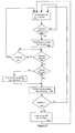
- FIG. 8 a flow chart of an embodiment of a process for programming a BID field 504 is illustrated.
- the user manually passes the cartridge barcode label 204 (if one is affixed) past the optical scanner 630 mounted on the front panel.
- the barcode scanner 630 is always looking for a barcode label 204 to read.
- the barcode scanner 630 might be activated by a menu or button if it is powered down or in a sleep mode. If no barcode label 204 is read as determined in block 802, processing loops back to block 800.
- the optical scanner 630 signals the system controller 602 that a scan has occurred.
- the data storage system 600 reads the output of the barcode scanner 630 in block 804.
- the data storage systems 600 monitors the cartridge holders to determine if a new cartridge 200 has been inserted into an empty slot. If a new cartridge 200 is not inserted before a timeout condition occurs as determined in block 805, the scanned value is discarded and processing loops back to block 800. If a cartridge is inserted, processing proceeds from block 806 to block 807 to determine if the scanned value is already present in one of the other cartridges 200 already loaded in cartridge holders. If the scanned value is not unique, processing branches to block 816 where the user is notified of the duplication and prompted to enter a new value.
- processing continues to block 808 where the BID is presented on the display 640 (and possibly beep the audible indicator) to notify the user that the scan has been successfully completed.
- the BID could be a numerical or alphanumerical value.
- the user can accept or edit the BID value in this embodiment.
- a message on the display 640 confirms with the user the slot that the scanned cartridge is being inserted into so that the cartridge library 608 can correlate the scan to the specific data cartridge 200.
- the display 640 may indicate the slot to use in some embodiments. Where the user doesn't accept the BID in block 810, processing loops back to block 800.
- the system controller 602 electronically stores the BID value in the BID field 504 of the cartridge metadata 508 in block 812.
- the BID value is now permanently stored in the data cartridge 200 and may be read electronically at any time without rescanning the barcode label 204.
- the optical scanning process need not be repeated when the data cartridge 200 is inserted again (into the same or different system) since the BID value is maintained even after the data cartridge 200 has been removed from the system 600.
- the barcode label 204 may be scanned and reprogrammed at any time in this embodiment. This may be done if the label is changed, for example.
- cartridges 200 may be shipped to the customer with barcode labels already affixed and the BID fields 504 already programmed so that the user does not have to perform the manual scanning step when first inserting the cartridge.
- the cartridge 200 may be pre-programmed at the factory with a unique BID value even if there is no label affixed. This may provide a default electronic identifier for the data cartridge 200.
- the data cartridge 200 may come with a unique value printed onto the barcode label 204 of the data cartridge 200 at the time of manufacture (e.g., by laser or ink-jet printer right onto the cartridge shell). This pre-printed identifier would correspond to the pre-programmed BID value.
- a pre-programmed, pre-printed BID value on the barcode label 204 may be globally unique using a controlled numbering system large enough to never require reuse of an identifying value in one embodiment. In this way, no two cartridges 200 can ever have the same identifying value. Different manufacturers of data cartridges 200 could coordinate their identifying values to prevent reuse.
- a flowchart 900 of an embodiment of a process for inventorying a cartridge library 608 is illustrated.
- the data storage system 600 may perform an inventory operation at any time (e.g., after power-on initialization or upon receipt of an inventory/audit command by the host computer system 120).
- This inventory operation is a purely electronic process of reading the metadata BID field 504 from the installed cartridges 200 and associating the BID values with physical or logical cartridge locations in the cartridge library 608. This has the advantage of completing an inventory very rapidly compared to robotic systems which must mechanically move the scanner past each cartridge.
- the depicted portion of the process begins in block 904 where an inventory request is received by the switched cartridge library 608 from the host computer 120.
- a loop including blocks 908, 912, 916, 920 and 924 each of the data cartridges 200 are read in succession.
- an unread data cartridge 200 is engaged by the switch 606 or logically engaged for embodiments that can read and write all data cartridges 200 simultaneously.
- the BID field 504 is electronically read from the metadata area 508 of the current data cartridge 200.
- the cartridge identifier or barcode label 204 is determined from the BID.
- the barcode label 204 could be the same as the BID or some function of the BID or a reformatted BID in various embodiments.
- the cartridge identifier is reported back to the host computer for the current cartridge location in block 920. Where there are additional un-inventoried cartridges as determined block 924, processing loops back to block 908 to inventory the remaining data cartridges 200. Where there are no more data cartridges 200 as determined in block 924, processing proceeds to block 928 where the cartridge library 608 indicates to the host computer 120 that the inventory is complete. Some embodiments may slow down the inventory process to more accurately model the delay likely to be experienced in a system with mechanical scanning.
- One advantage of this embodiment is that the system controller 602 can see the values of the BIDs of all the data cartridges 200 loaded into the cartridge library 608 at any one time and may prevent duplicate values from confusing an application on the host computer 120. If a data cartridge 200 with a duplicate value is inserted into the library 608, the system controller 602 may notify the user through the front panel interface, on-line management interface or error message back to the host application that a duplication exists and request or require corrective action. Some embodiments could detect duplicates and automatically change BIDs to remove redundancy.
- the embodiments may be described as a process which is depicted as a flowchart, a flow diagram, a data flow diagram, a structure diagram, or a block diagram. Although a flowchart may describe the operations as a sequential process, many of the operations can be performed in parallel or concurrently. In addition, the order of the operations may be re-arranged.
- a process is terminated when its operations are completed, but could have additional steps not included in the figure.
- a process may correspond to a method, a function, a procedure, a subroutine, a subprogram, etc. When a process corresponds to a function, its termination corresponds to a return of the function to the calling function or the main function.
- the term “storage medium” may represent one or more devices for storing data, including read only memory (ROM), random access memory (RAM), magnetic RAM, core memory, magnetic disk storage mediums, optical storage mediums, flash memory devices and/or other machine readable mediums for storing information.
- ROM read only memory
- RAM random access memory
- magnetic RAM magnetic RAM
- core memory magnetic disk storage mediums
- optical storage mediums flash memory devices and/or other machine readable mediums for storing information.
- machine-readable medium includes, but is not limited to portable or fixed storage devices, optical storage devices, wireless channels, and/or various other mediums capable of storing, containing or carrying instruction(s) and/or data.
- embodiments may be implemented by hardware, software, scripting languages, firmware, middleware, microcode, hardware description languages, and/or any combination thereof.
- the program code or code segments to perform the necessary tasks may be stored in a machine readable medium such as a storage medium.
- a code segment or machine-executable instruction may represent a procedure, a function, a subprogram, a program, a routine, a subroutine, a module, a software package, a script, a class, or any combination of instructions, data structures, and/or program statements.
- a code segment may be coupled to another code segment or a hardware circuit by passing and/or receiving information, data, arguments, parameters, and/or memory contents. Information, arguments, parameters, data, etc. may be passed, forwarded, or transmitted via any suitable means including memory sharing, message passing, token passing, network transmission, etc.
- Implementation of the techniques described above may be done in various ways. For example, these techniques may be implemented in hardware, software, or a combination thereof.
- the processing units may be implemented within one or more application specific integrated circuits (ASICs), digital signal processors (DSPs), digital signal processing devices (DSPDs), programmable logic devices (PLDs), field programmable gate arrays (FPGAs), processors, controllers, micro-controllers, microprocessors, other electronic units designed to perform the functions described above, and/or a combination thereof.
- ASICs application specific integrated circuits
- DSPs digital signal processors
- DSPDs digital signal processing devices
- PLDs programmable logic devices
- FPGAs field programmable gate arrays
- processors controllers, micro-controllers, microprocessors, other electronic units designed to perform the functions described above, and/or a combination thereof.
- the techniques, processes and functions described herein may be implemented with modules (e.g., procedures, functions, and so on) that perform the functions described herein.
- the software codes may be stored in memory units and executed by processors.
- the memory unit may be implemented within the processor or external to the processor, in which case the memory unit can be communicatively coupled to the processor using various known techniques.
Landscapes
- Automatic Tape Cassette Changers (AREA)
- Dry Development In Electrophotography (AREA)
- Stored Programmes (AREA)
- Storage Device Security (AREA)
Applications Claiming Priority (1)
| Application Number | Priority Date | Filing Date | Title |
|---|---|---|---|
| US11/279,083 US7694884B2 (en) | 2006-04-07 | 2006-04-07 | Removable cartridge identification system |
Publications (2)
| Publication Number | Publication Date |
|---|---|
| EP1843345A2 true EP1843345A2 (de) | 2007-10-10 |
| EP1843345A3 EP1843345A3 (de) | 2009-02-11 |
Family
ID=38331277
Family Applications (1)
| Application Number | Title | Priority Date | Filing Date |
|---|---|---|---|
| EP07105898A Withdrawn EP1843345A3 (de) | 2006-04-07 | 2007-04-10 | Erkennungssystem für abnehmbare Kassette |
Country Status (2)
| Country | Link |
|---|---|
| US (1) | US7694884B2 (de) |
| EP (1) | EP1843345A3 (de) |
Cited By (1)
| Publication number | Priority date | Publication date | Assignee | Title |
|---|---|---|---|---|
| US9350806B2 (en) | 2012-09-07 | 2016-05-24 | International Business Machines Corporation | Zero copy data transfers without modifying host side protocol stack parameters |
Families Citing this family (5)
| Publication number | Priority date | Publication date | Assignee | Title |
|---|---|---|---|---|
| JP4460496B2 (ja) * | 2005-07-07 | 2010-05-12 | 富士フイルム株式会社 | テープカートリッジ管理システムおよびテープカートリッジ |
| CA2690506C (en) * | 2009-01-20 | 2016-05-10 | Parata Systems, Llc | Methods, systems, and apparatus for determining and automatically programming network addresses for devices operating in a network |
| US9666223B2 (en) * | 2015-10-02 | 2017-05-30 | International Business Machines Corporation | Enhanced tape library cataloging |
| JP2018129103A (ja) * | 2017-02-06 | 2018-08-16 | 富士フイルム株式会社 | 記録システム及び記録方法 |
| US12423017B2 (en) * | 2020-04-03 | 2025-09-23 | N.F. Smith & Associates, LP | System and method for performing and verifying data erasure |
Family Cites Families (14)
| Publication number | Priority date | Publication date | Assignee | Title |
|---|---|---|---|---|
| US5303034A (en) * | 1992-05-01 | 1994-04-12 | Storage Technology Corporation | Robotics targeting system |
| US6081857A (en) * | 1993-12-17 | 2000-06-27 | Storage Technology Corporation | System and method for identifying and managing data storage volumes using electromagnetic transducers |
| US5568455A (en) * | 1995-05-18 | 1996-10-22 | Sony Corporation | System and method for the storage and retrieval of off-line performatted optical media |
| US6154790A (en) * | 1998-07-10 | 2000-11-28 | International Business Machines | Monitoring and reporting hard disk drives identification using radio frequency |
| US6138909A (en) * | 1998-07-22 | 2000-10-31 | Advanced Digital Information Corporation | Media handling system and method |
| US6201474B1 (en) * | 1998-10-21 | 2001-03-13 | Intermec Ip Corp. | Magnetic tape storage media having RFID transponders |
| JP2002063778A (ja) | 2000-08-18 | 2002-02-28 | Sony Corp | ディスクカートリッジおよびその製造方法ならびに記録再生システム |
| US6731444B2 (en) * | 2000-09-28 | 2004-05-04 | Seagate Technology Llc | Head-disc assembly with embedded product identification code |
| US6957291B2 (en) * | 2001-03-29 | 2005-10-18 | Quantum Corporation | Removable disk storage array emulating tape library having backup and archive capability |
| US7010647B1 (en) * | 2002-12-13 | 2006-03-07 | The United States Of America As Represented By The Secretary Of The Army | Computer system with removable data storage device and method |
| US7080203B2 (en) * | 2003-01-21 | 2006-07-18 | International Business Machines Corporation | Serial EEPROM for volume identification and drive specific information storage in a hard disk drive library |
| JP4331750B2 (ja) | 2003-06-30 | 2009-09-16 | トムソン ライセンシング | ビデオ録画または再生のためのリムーバブルメディア装置 |
| US20050188246A1 (en) * | 2004-02-25 | 2005-08-25 | Emberty Robert G. | Persistent worldwide names assigned to removable media storage |
| US7246210B2 (en) | 2004-11-08 | 2007-07-17 | Prostor Systems, Inc. | Archival cartridge management system with auto-refresh |
-
2006
- 2006-04-07 US US11/279,083 patent/US7694884B2/en active Active
-
2007
- 2007-04-10 EP EP07105898A patent/EP1843345A3/de not_active Withdrawn
Cited By (2)
| Publication number | Priority date | Publication date | Assignee | Title |
|---|---|---|---|---|
| US9350806B2 (en) | 2012-09-07 | 2016-05-24 | International Business Machines Corporation | Zero copy data transfers without modifying host side protocol stack parameters |
| US9578132B2 (en) | 2012-09-07 | 2017-02-21 | International Business Machines Corporation | Zero copy data transfers without modifying host side protocol stack parameters |
Also Published As
| Publication number | Publication date |
|---|---|
| EP1843345A3 (de) | 2009-02-11 |
| US20070235516A1 (en) | 2007-10-11 |
| US7694884B2 (en) | 2010-04-13 |
Similar Documents
| Publication | Publication Date | Title |
|---|---|---|
| US6523749B2 (en) | Apparatus and method for retrieving data cartridge information external to a media storage system | |
| US6466990B2 (en) | System and method for data storage management | |
| US6663003B2 (en) | Apparatus and method for retrieving data related to a data cartridge in a media storage system | |
| EP1843345A2 (de) | Erkennungssystem für abnehmbare Kassette | |
| JP2566725B2 (ja) | マガジン制御を有するスタッカー/オートローダー装置 | |
| US8850080B2 (en) | Mobile media identification system for use with a storage device | |
| JP4191661B2 (ja) | ライブラリ装置、制御方法及びプログラム | |
| CN103577961A (zh) | 硬件设备管理系统及其信息的处理、查询方法 | |
| US5721655A (en) | Method for labeling a removable media cartridge | |
| WO2020028905A1 (en) | Combination barcode reader and radio frequency identification read/write device | |
| US20040153205A1 (en) | Use of cartridge memory for storing logical library association information | |
| JP4473109B2 (ja) | 創薬用冷凍保管容器rfidタグ一括読み書き装置 | |
| US7472405B2 (en) | Apparatus system and method for using multiple detectors to conduct an inventory of a data storage library | |
| US7441320B2 (en) | Method of validating manufacturing configurations during hardware assembly | |
| CN117795522A (zh) | 在无菌物品回路中的智能端口多功能读取/识别设备 | |
| US20020114096A1 (en) | Apparatus and method for retrieving data cartridge information in a cartridge receiving device | |
| US20080238633A1 (en) | Computer System with ID Tag | |
| US7535669B2 (en) | Detection of data cartridges in an automated data storage library | |
| JP2010152993A (ja) | ライブラリ装置及びその記憶媒体管理方法,プログラム | |
| WO2019162984A1 (ja) | テープフィーダのサポートプレート種/部品種組み合わせ確認システム及びサポートプレート種/部品種組み合わせ確認方法 | |
| US20070127322A1 (en) | Apparatus system and method for managing control path commands in an automated data storage library | |
| JP2012243346A (ja) | メディアライブラリ装置、メディア情報管理方法およびメディア情報管理プログラム | |
| US20070043791A1 (en) | Data backup system | |
| US20250050678A1 (en) | Smart card case with software integration for organization, location tracking, and protection of collectibles secured therein | |
| CN209641347U (zh) | 一种盘匣自动操作工具 |
Legal Events
| Date | Code | Title | Description |
|---|---|---|---|
| PUAI | Public reference made under article 153(3) epc to a published international application that has entered the european phase |
Free format text: ORIGINAL CODE: 0009012 |
|
| AK | Designated contracting states |
Kind code of ref document: A2 Designated state(s): AT BE BG CH CY CZ DE DK EE ES FI FR GB GR HU IE IS IT LI LT LU LV MC MT NL PL PT RO SE SI SK TR |
|
| AX | Request for extension of the european patent |
Extension state: AL BA HR MK YU |
|
| PUAL | Search report despatched |
Free format text: ORIGINAL CODE: 0009013 |
|
| AK | Designated contracting states |
Kind code of ref document: A3 Designated state(s): AT BE BG CH CY CZ DE DK EE ES FI FR GB GR HU IE IS IT LI LT LU LV MC MT NL PL PT RO SE SI SK TR |
|
| AX | Request for extension of the european patent |
Extension state: AL BA HR MK RS |
|
| AKX | Designation fees paid | ||
| REG | Reference to a national code |
Ref country code: DE Ref legal event code: 8566 |
|
| STAA | Information on the status of an ep patent application or granted ep patent |
Free format text: STATUS: THE APPLICATION IS DEEMED TO BE WITHDRAWN |
|
| 18D | Application deemed to be withdrawn |
Effective date: 20090812 |