EP1843363B1 - Elektrisches Schaltgerät mit Kontaktabbrand Nachstellvorrichtung - Google Patents
Elektrisches Schaltgerät mit Kontaktabbrand Nachstellvorrichtung Download PDFInfo
- Publication number
- EP1843363B1 EP1843363B1 EP07105241A EP07105241A EP1843363B1 EP 1843363 B1 EP1843363 B1 EP 1843363B1 EP 07105241 A EP07105241 A EP 07105241A EP 07105241 A EP07105241 A EP 07105241A EP 1843363 B1 EP1843363 B1 EP 1843363B1
- Authority
- EP
- European Patent Office
- Prior art keywords
- contacts
- wear
- movable
- movable member
- armature
- Prior art date
- Legal status (The legal status is an assumption and is not a legal conclusion. Google has not performed a legal analysis and makes no representation as to the accuracy of the status listed.)
- Active
Links
Images




Classifications
-
- H—ELECTRICITY
- H01—ELECTRIC ELEMENTS
- H01H—ELECTRIC SWITCHES; RELAYS; SELECTORS; EMERGENCY PROTECTIVE DEVICES
- H01H1/00—Contacts
- H01H1/0015—Means for testing or for inspecting contacts, e.g. wear indicator
-
- H—ELECTRICITY
- H01—ELECTRIC ELEMENTS
- H01H—ELECTRIC SWITCHES; RELAYS; SELECTORS; EMERGENCY PROTECTIVE DEVICES
- H01H3/00—Mechanisms for operating contacts
- H01H3/22—Power arrangements internal to the switch for operating the driving mechanism
- H01H3/28—Power arrangements internal to the switch for operating the driving mechanism using electromagnet
-
- H—ELECTRICITY
- H01—ELECTRIC ELEMENTS
- H01H—ELECTRIC SWITCHES; RELAYS; SELECTORS; EMERGENCY PROTECTIVE DEVICES
- H01H1/00—Contacts
- H01H1/12—Contacts characterised by the manner in which co-operating contacts engage
- H01H1/14—Contacts characterised by the manner in which co-operating contacts engage by abutting
- H01H1/20—Bridging contacts
-
- H—ELECTRICITY
- H01—ELECTRIC ELEMENTS
- H01H—ELECTRIC SWITCHES; RELAYS; SELECTORS; EMERGENCY PROTECTIVE DEVICES
- H01H1/00—Contacts
- H01H1/12—Contacts characterised by the manner in which co-operating contacts engage
- H01H1/14—Contacts characterised by the manner in which co-operating contacts engage by abutting
- H01H1/22—Contacts characterised by the manner in which co-operating contacts engage by abutting with rigid pivoted member carrying the moving contact
Definitions
- the present invention relates to an electrical switch device comprising in particular a device for compensating for wear of the contacts.
- a switch-type electrical apparatus, circuit breaker or contactor-circuit breaker typically has, on each power pole, separable movable contacts of fixed contacts, actuated in motion by means of an electromagnet to switch an electric charge to be controlled.
- This electromagnet generally comprises a fixed yoke and an armature which is movable relative to the fixed yoke, thus forming a magnetic circuit having a variable gap.
- the electromagnet also has an electromagnetic excitation coil in which can circulate an excitation current which then creates a magnetic field causing a displacement of the movable armature relative to the fixed yoke.
- the patent application FR 2,580,115 discloses a breaker-type electrical switch device comprising an automatic wear-compensating device of its arc contacts. This device acts to maintain a dead stroke of its arc contacts at a constant value so that the opening of the arcing contacts occurs systematically after that of the main contacts.
- the device proposed in this document is complex and does not allow to maintain a race opening and closing of the main contacts at a constant value over time.
- the object of the invention is to provide an electrical switch device in which the opening or closing stroke of the movable contacts is maintained at a constant value over time without impairing the proper operation of the device.
- the actuating device allows, as and when the contacts, to keep the opening or closing stroke to a constant value and an actuating stroke to a constant length and therefore also an effort constant contact pressure and a constant dynamic regardless of the wear of the contacts.
- the position of the stop piece therefore follows the progression of the wear of the contacts.
- the stop piece can move to limit the opening stroke or the closing stroke according to the arrangement of the pieces together.
- the stop piece limits the opening stroke of the movable member and defines the open position of the movable member taking into account the wear of the contacts.
- the abutment piece then cooperates with the movable member and is driven by the movable member during the closing stroke, a distance corresponding to the progression of wear of the contacts.
- the wear-compensating device of the contacts comprises notches for marking different positions of the abutment piece as the wear of the contacts increases.
- the automatic wear-compensating device comprises stacked lamellae capable of interposing with the wear of the contacts between the abutment piece and a fixed armature.
- the slats can be inserted by a spring or actuated by a magnet.
- the contact wear compensating device comprises hydraulic or pneumatic compensation means between the abutment piece and a fixed armature.
- the abutment piece comprises two adjacent sealed chambers that can communicate via a valve adapted to let a fluid pass in one direction, from one chamber to another, as and as wear of the contacts.
- the position of the movable armature of the actuator relative to the movable member is self-adaptable according to the progression of the wear of the contacts.
- the automatic compensation device of the actuating stroke consists for example of connecting the moving armature and the movable member by a telescopic link.
- the movable armature of the actuator cooperates with the movable member by a hydraulic or pneumatic system, the movable armature comprising return means for driving the movable member towards the one of its opening or closing positions.
- the movable armature of the actuator cooperates with the movable member via a disengageable sleeve forming a divergent receiving a conical end of an actuating rod integral with the movable member, mobile armature comprising return means for driving the movable member towards one of its open or closed positions.
- the movable member is for example a movable bridge carrying two movable contacts.
- the actuation device described above may in particular be implemented in a switch-type electrical appliance switch, circuit breaker or contactor-breaker.
- An electrical switch device has one or more power poles.
- the switchgear comprises upstream current lines (source lines), which establish the electrical continuity between the power supply network and the power poles, and downstream power lines (load lines) which establish the continuity electrical between the poles of the electrical switch device and an electrical load, usually an electric motor, that it is desired to control and / or protect with the electrical switch device.
- the upstream current lines are connected to or disconnected from the downstream current lines by an actuating device having pole contacts which may be single or double cut.
- the actuating device according to the invention which is described below, can be used in a switch-type electric switch, circuit breaker, contactor-circuit breaker with single or double break.
- the electrical switch device can be poles breakers or contact poles.
- the actuation device shown is a double-break contactor pole and on the Figures 7A to 7D , the actuating device is single-pole switch pole.
- a pole of the actuating device comprises two movable contacts 20 carried by a movable bridge 2 and two fixed contacts 30 located vis-a-vis.
- the fixed and movable contacts 20 are in the form of pellets of conductive metal material.
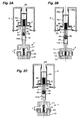
- the movable bridge 2 is actuated along an axis (A) by an actuator 1 to switch an electrical circuit, between an open position in which its movable contacts 20 are separated from the fixed contacts 30 ( Figure 2A ) and a closed position in which its movable contacts 20 bear against the fixed contacts 30 ( Figure 2B ).
- the closing force of the contacts 20, 30 is provided by a contact pressure spring 40 which presses on the movable bridge 2 to press the movable contacts 20 against the fixed contacts 30.
- the movable bridge 2 is mounted on an actuating rod 4, 4 'connected at a first end to an actuator 1 electrically controlled electromagnetic type such as for example a control electromagnet able to control between its two positions.
- the movable bridge 2 is slidably mounted on the actuating rod 4, 4 'and applied against an abutment thereof by the contact pressure spring 40 extending between the movable bridge 2 and a second end of the rod. actuation 4, 4 '.
- the control electromagnet type actuator 1 typically comprises a fixed yoke 10, a movable armature 11, a return spring 12 and a control coil 13 (FIG. FIGS. 2A to 2C ).
- the moving armature 11 is attracted by the fixed yoke 10 by passing an excitation current in the control coil 13 driving the movable bridge 2 in the closed position ( Figure 2B ). If the current flowing in the control coil 13 is cut off, the mobile armature 11 returns to its initial position by mechanical effect thanks to the return spring 12 ( Figure 2C ).
- the return movement of the movable armature 11 can be performed differently using a voice coil principle.
- Other types of actuator may also be envisaged, for example of the piezoelectric type.
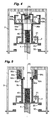
- the figures 1 and 3 to 5 show different variants of the device for automatic catch-up of the contacts.
- the figure 1 also shows a first configuration of a device for automatically compensating the length of the actuating stroke.
- the figure 6 shows a second configuration of the device for automatically compensating the length of the actuating stroke. It is obvious that the different variants and configurations described below and represented on these Figures may be combined with each other to produce different versions of the actuating device of the invention.
- a device for compensating for wear of the contacts comprises a movable stop piece 5a, 5b, 5c, 5d driven in translation as the contacts 20, 30 wear.
- This stop piece 5a , 5b, 5c, 5d is adapted to take several different successive positions by following the progression of the wear of the contacts 20, 30.
- the abutment piece 5a, 5b, 5c, 5d has a first end to which it is guided in translation. relative to a fixed armature 3 carrying the fixed contacts 30 and has a second end against which bears the movable bridge 2 when in the open position.
- the movable bridge 2 has means for moving the abutment piece 5a, 5b, 5c, 5d as the contacts 20, 30 wear away so as to keep the fixed contacts 20 in the open position of the bridge mobile 2 at a constant distance from the fixed contacts 30 regardless of the wear of the contacts 20, 30.
- the movable bridge 2 cooperates with the abutment piece 5a, 5b, 5c, 5d and has a flange 21 adapted to come against a flange 53 corresponding to the abutment piece 5a, 5b, 5c, 5d when it is in the closed position ( Figure 2B ).
- a first means consists in providing the abutment piece 5a notches 52a or frets cooperating with notches 32a or corresponding frets formed on the fixed armature 3 of the device.
- the stop piece 5a driven by the moving bridge 2 moves in translation from one to several notches to reduce the length of the stroke between the contacts 20, 30. a value corresponding to the progression of the wear of the contacts 20, 30.
- FIGS. FIGS. 2A to 2C The operation of the wear-compensating device of the contacts using this first means is more particularly illustrated in FIGS. FIGS. 2A to 2C .
- the contacts 20, 30 are new and the movable bridge 2 is in the open position. After a number of maneuvers, the contacts 20, 30 begin to wear out.
- the Figure 2B shows the movable bridge 2 in the closed position with worn contacts.
- the movable bridge 2 has driven the abutment piece 5a in translation of one or more notches to take account at each maneuver of the actual state of wear of the contacts and thus to maintain the travel between the contacts at a constant L value.
- the stop piece 5a has thus been translated by a length corresponding to the total wear thickness of the contacts 20, 30.
- a second means consists in inserting lamellae 62b, 62c between the abutment piece 5b, 5c and the fixed armature 3 of the device as the contacts 20, 30 wear.
- the lamellae 62b, 62c are for example divided into two groups and are stacked in two housings 50b, 51b, 50c, 51c symmetrical, for example semicircular, formed in the abutment piece 5b ( figure 4 ) or in the fixed armature 3 ( figure 5 ).
- a gap 33b, 34b is provided between the abutment piece 5b and the fixed armature 3.
- the two interstices 33b, 34b created are of different volumes so as to be able to alternately interchange a lamella 62b of each group as the wear of the contacts 20, 30 progresses.
- the stop piece 5b is driven in translation by the movable bridge 2 and marks each new position by inserting at least one new lamella 62b of a group in a gap 33b, 34b.
- the slats 62b of each group can be pushed into their gap 33b, 34b by a prestressed spring blade 63b.
- the lamellae 62b are each pierced with an orifice through which the spring blade 63b passes, this orifice being of increasing size through the lamellae as the stacking progresses.
- the abutment piece 5b is advantageously mounted on a spring 31b that is increasingly biased during the translation of the abutment piece 5b with respect to the fixed armature 3 as the contacts 20, 30 and 20 wear out. the number of lamellae interposed between the fixed armature 3 and the abutment piece 5b.
- the lamellae 62c of each group are made of metallic material and are drawn, as and when the contacts 20, 30 are worn, between the abutment piece 5c and the fixed armature 3 by a permanent magnet 63c.
- the magnets 63c may be integral with the abutment piece 5c or the fixed armature 3.
- a prestressed spring 64c is positioned between the top of the stack of the lamellae 62c and the upper wall of the housing 50c, 51c to permanently solicit the stack of slats 62c.
- a third means consists in compensating the wear of the contacts by a pneumatic or hydraulic system.
- a first sealed chamber 50d is formed in the abutment piece 5d. This first chamber 50d is separated from a second chamber 51 d sealed via a valve 62d.
- the second chamber 51d is delimited by the abutment piece 5d and the fixed armature 3 and is expandable as a function of the displacement of the abutment piece 5d.
- the valve 62d is mounted between the two chambers 50d, 51d on the abutment piece 5d and is able to pass a fluid from the first chamber 50d to the second chamber 51d as the displacement piece 5d moves. caused by the progression of contact wear.
- the fluid used may be a gas or a mixture of gases such as air or be a liquid such as oil.
- the displacement of the abutment piece 5a, 5b, 5c, 5d as the wear of the contacts 20, 30 causes the change of position of the movable bridge 2 and thus the displacement of the actuating rod 4, 4 .
- the change of position of the movable bridge 2 as the wear of the contacts 20, 30 thus impacts the length of the actuating stroke of the movable armature 11 of the actuator 1 relative to its fixed yoke 10
- the actuating rod 4, 4' is connected to the mobile armature 11 by a telescopic link, automatically adjustable according to the wear of the contacts 20, 30.
- the compensation of the length L 'of the actuating stroke can be achieved by employing pneumatic means.
- the actuating rod 4 comprises a first chamber 41 which is filled with a gas or a mixture of gases such as air and which is sealed on one side by a piston 110 secured to the movable armature 11 and movable in the chamber 41 in a direction parallel to the axis of the device and on the other side by a wall on which is mounted a valve 43 regulating the flow of air to a second chamber 42 communicating with the outside, the valve 43 being mounted to allow only the evacuation of air from the first chamber 41 to the second chamber 42.
- a gas or a mixture of gases such as air
- this first configuration of the compensation device of the actuating stroke functions as follows:
- the piston 110 of the mobile armature 11 brought back by its spring 12, engages more deeply in the first chamber 41, pushing the air through the valve 43 to the second chamber 42 and outward to maintain the actuating stroke at a constant length L regardless of the degree of wear of the contacts.
- the return spring 12 of the mobile armature 11 must have a greater stiffness constant than that of the spring mounted on the valve 43. The movable armature 11 thus takes a new position relative to the actuating rod. 4 to maintain the actuating stroke at a constant length compensating for the displacement of the moving bridge caused by wear of the contacts.
- compensation can be achieved by employing mechanical means.
- the actuating rod 4 ' has a conical end 41' cooperating with a sleeve 42 'having a corresponding divergent recess for driving the rod 4' in translation from the open position to the closed position during the movement of the mobile armature 11 of the actuator to the fixed yoke 10.
- this sleeve 42' bears on the inner wall of a sleeve 110 'formed on the movable armature 11 of the actuator 1 along the axis (A) of the device.
- This sleeve 42 ' is disengageable in the sleeve 110' under the action of a prestressed spring 44 'mounted between the actuating rod 4' and the sleeve 42 'to gradually fill the space created by the displacement of the actuating rod 4 ', this displacement being caused by the wear of the contacts 20, 30.
- the sleeve 42' is pushed against the cone 41 ' of the rod 4 'by the spring 44' prestressed so as to reduce the length of the actuating stroke by the depression of the rod 4 'in the sleeve 110' of the mobile armature 11.
- FIGS. 7A to 7D illustrate the principle of operation of a wear-compensating device for an actuating device having a single-break pole.
- the movable contact 201 is carried by a lever 200 pivotally actuated between an open position ( Figure 7B ) and a closed position ( Figure 7A ) relative to a fixed contact 301.
- the lever 200 cooperates with a stop piece 500 and drives in translation as the wear of the contacts.
- This stop piece 500 is intended to mark a new position of the lever 200 as a function of the progression of the wear of the contacts 201, 301 to maintain the travel between the movable contact 201 and the fixed contact 301 at a constant value.
- the stop piece 500 carries for example one or more notches 501 cooperating for example with corresponding notches 302 formed on a fixed armature 300.
- the other pneumatic means, Hydraulic or lamellae described for the double-break pole can be easily transposed into a single-pole.
Landscapes
- Physics & Mathematics (AREA)
- Electromagnetism (AREA)
- Push-Button Switches (AREA)
- Braking Arrangements (AREA)
- Actuator (AREA)
- Electromagnets (AREA)
- Electrical Discharge Machining, Electrochemical Machining, And Combined Machining (AREA)
- Coupling Device And Connection With Printed Circuit (AREA)
- Keying Circuit Devices (AREA)
- Driving Mechanisms And Operating Circuits Of Arc-Extinguishing High-Tension Switches (AREA)
Claims (13)
- Betätigungseinrichtung für einen elektrischen Schalter, die aufweist:- ein bewegliches Organ (2, 200), das mindestens einen beweglichen Kontakt (20, 201) trägt, der einen Öffnungs- oder Schließhub bezüglich eines festen Kontakts (30, 301) ausführt, um einen elektrischen Stromkreis zu steuern,- einen Stellantrieb (1), der ein festes Joch (10) und einen beweglichen Anker (11) aufweist, wobei der bewegliche Anker in Bewegung fest mit dem beweglichen Organ (2, 200) verbunden und fähig ist, einen Betätigungshub bezüglich des festen Jochs (10) auszuführen, um das bewegliche Organ (2, 200) in seinen Öffnungs-oder Schließhub anzutreiben,- eine automatische Vorrichtung zum automatischen Verschleißausgleich der Kontakte, um den Öffnungs- oder Schließhub zwischen dem festen Kontakt (30, 301) und dem beweglichen Kontakt (20, 201) unabhängig vom Verschleiß der Kontakte (20, 30, 201, 301) auf einem konstanten Wert (L) zu halten,- eine Vorrichtung zur automatischen Kompensation der Länge des Betätigungshubs (L') in Abhängigkeit vom Verschleiß der Kontakte (20, 30, 201, 301),dadurch gekennzeichnet, dass- die Vorrichtung zum Verschleißausgleich der Kontakte ein Anschlagbauteil (5a, 5b, 5c, 5d, 500) aufweist, das den Öffnungs- oder Schließhub des beweglichen Organs (2, 200) begrenzt und sich im Laufe des Verschleißes der Kontakte (20, 30, 201, 301) verschieben kann.
- Vorrichtung nach Anspruch 1, dadurch gekennzeichnet, dass das Anschlagbauteil (5a, 5b, 5c, 5d, 500) mit dem beweglichen Organ (2, 200) zusammenwirkt und vom beweglichen Organ beim Schließhub über eine Strecke angetrieben wird, die dem Fortschreiten des Verschleißes der (20, 30, 201, 301) entspricht.
- Vorrichtung nach Anspruch 1 oder 2, dadurch gekennzeichnet, dass die Vorrichtung zum Verschleißausgleich der Kontakte Rasten (32a, 52a) aufweist, um verschiedene Stellungen des Anschlagbauteils (5a, 500) im Laufe des Verschleißes der Kontakte zu markieren.
- Vorrichtung nach Anspruch 1 oder 2, dadurch gekennzeichnet, dass die Vorrichtung zum automatischen Verschleißausgleich gestapelte Lamellen (62b, 62c) aufweist, die fähig sind, sich im Laufe des Verschleißes der Kontakte (20, 30) zwischen das Anschlagbauteil (5b, 5c) und einen festen Anker (3) einzufügen.
- Vorrichtung nach Anspruch 4, dadurch gekennzeichnet, dass die Lamellen (62b) durch eine Feder (63b) eingefügt werden.
- Vorrichtung nach Anspruch 4, dadurch gekennzeichnet, dass die Lamellen (62c) von einem Magnet (63c) betätigt werden.
- Vorrichtung nach Anspruch 1 oder 2, dadurch gekennzeichnet, dass die Vorrichtung zum Verschleißausgleich der Kontakte hydraulische oder pneumatische Kompensationseinrichtungen zwischen dem Anschlagbauteil (5d) und einem festen Anker (3) aufweist.
- Vorrichtung nach Anspruch 7, dadurch gekennzeichnet, dass das Anschlagbauteil (5d) zwei benachbarte dichte Kammern (50d, 51d) aufweist, die über ein Ventil (62d) kommunizieren können, das im Lauf des Verschleißes der Kontakte (20, 30) ein Fluid in einer Richtung von einer Kammer zur anderen durchlassen kann.
- Vorrichtung nach einem der Ansprüche 1 bis 8, dadurch gekennzeichnet, dass die Vorrichtung zur automatischen Kompensation der Länge (L') des Betätigungshubs darin besteht, den beweglichen Anker (11) und das bewegliche Organ (2, 200) über eine Teleskopverbindung miteinander zu verbinden.
- Vorrichtung nach Anspruch 9, dadurch gekennzeichnet, dass der bewegliche Anker (11) des Stellantriebs (1) mit dem beweglichen Organ (2, 200) über ein hydraulisches oder ein pneumatisches System zusammenwirkt, und dass der bewegliche Anker (11) Rückstellmittel (12) aufweist, um das bewegliche Organ (2, 200) in eine seiner Öffnungs-oder Schließstellungen anzutreiben.
- Vorrichtung nach Anspruch 9, dadurch gekennzeichnet, dass der bewegliche Anker (11) des Stellantriebs (1) mit dem beweglichen Organ (2) über eine ausrückbare Muffe (42') zusammenwirkt, welche eine Ummantelung bildet, die ein kegelförmiges Ende (41') einer Betätigungsstange (4') aufnimmt, die fest mit dem beweglichen Organ (2) verbunden ist.
- Betätigungsvorrichtung nach einem der Ansprüche 1 bis 11, dadurch gekennzeichnet, dass das bewegliche Organ eine bewegliche Brücke (2) ist.
- Elektrischer Schalter, dadurch gekennzeichnet, dass er eine Betätigungseinrichtung nach einem der Ansprüche 1 bis 12 aufweist.
Priority Applications (1)
| Application Number | Priority Date | Filing Date | Title |
|---|---|---|---|
| PL07105241T PL1843363T3 (pl) | 2006-04-05 | 2007-03-29 | Elektryczna aparatura przełącznika z urządzeniem kompensującym zużycie styków |
Applications Claiming Priority (1)
| Application Number | Priority Date | Filing Date | Title |
|---|---|---|---|
| FR0651218A FR2899722B1 (fr) | 2006-04-05 | 2006-04-05 | Appareil electrique interrupteur avec dispositif de rattrapage d'usure des contacts |
Publications (2)
| Publication Number | Publication Date |
|---|---|
| EP1843363A1 EP1843363A1 (de) | 2007-10-10 |
| EP1843363B1 true EP1843363B1 (de) | 2009-07-22 |
Family
ID=37432225
Family Applications (1)
| Application Number | Title | Priority Date | Filing Date |
|---|---|---|---|
| EP07105241A Active EP1843363B1 (de) | 2006-04-05 | 2007-03-29 | Elektrisches Schaltgerät mit Kontaktabbrand Nachstellvorrichtung |
Country Status (6)
| Country | Link |
|---|---|
| EP (1) | EP1843363B1 (de) |
| AT (1) | ATE437445T1 (de) |
| DE (1) | DE602007001618D1 (de) |
| ES (1) | ES2327460T3 (de) |
| FR (1) | FR2899722B1 (de) |
| PL (1) | PL1843363T3 (de) |
Families Citing this family (3)
| Publication number | Priority date | Publication date | Assignee | Title |
|---|---|---|---|---|
| CN101707165B (zh) * | 2009-09-29 | 2012-09-26 | 湖北盛佳电器设备有限公司 | 具有自动合闸功能的内置式a型智能断路器 |
| CN114203461B (zh) * | 2020-09-18 | 2026-02-13 | 通用设备和制造公司 | 电气开关接触部组 |
| CN119786293A (zh) * | 2025-01-16 | 2025-04-08 | 重庆大学 | 一种用于融冰与防雷状态切换的双稳态永磁地线刀闸 |
Family Cites Families (4)
| Publication number | Priority date | Publication date | Assignee | Title |
|---|---|---|---|---|
| US2150566A (en) * | 1937-07-01 | 1939-03-14 | Ite Circuit Breaker Ltd | Circuit interrupter |
| US2981817A (en) * | 1958-08-20 | 1961-04-25 | Basic Products Corp | Switch |
| FR2580115A1 (en) * | 1985-04-09 | 1986-10-10 | Merlin Gerin | Electrical circuit breaker with wear compensation device |
| DE19743037A1 (de) * | 1997-09-30 | 1999-04-01 | Siemens Ag | Schutzschalter |
-
2006
- 2006-04-05 FR FR0651218A patent/FR2899722B1/fr not_active Expired - Fee Related
-
2007
- 2007-03-29 AT AT07105241T patent/ATE437445T1/de not_active IP Right Cessation
- 2007-03-29 DE DE602007001618T patent/DE602007001618D1/de active Active
- 2007-03-29 ES ES07105241T patent/ES2327460T3/es active Active
- 2007-03-29 EP EP07105241A patent/EP1843363B1/de active Active
- 2007-03-29 PL PL07105241T patent/PL1843363T3/pl unknown
Also Published As
| Publication number | Publication date |
|---|---|
| ES2327460T3 (es) | 2009-10-29 |
| EP1843363A1 (de) | 2007-10-10 |
| ATE437445T1 (de) | 2009-08-15 |
| FR2899722A1 (fr) | 2007-10-12 |
| PL1843363T3 (pl) | 2009-12-31 |
| DE602007001618D1 (de) | 2009-09-03 |
| FR2899722B1 (fr) | 2008-08-15 |
Similar Documents
| Publication | Publication Date | Title |
|---|---|---|
| EP2126951B1 (de) | Hybrider elektromagnetischer aktor | |
| WO2011073539A1 (fr) | Actionneur electromagnetique a accrochage magnetique et dispositif de coupure comportant un tel actionneur | |
| FR2573912A1 (fr) | Interrupteur electrique a ecran | |
| EP1843363A1 (de) | Elektrisches Schaltgerät mit Kontaktabbrand Nachstellvorrichtung | |
| WO2012042124A1 (fr) | Actionneur electromagnetique a accrochage magnetique et dispositif de coupure comportant un tel actionneur | |
| CA1256919A (fr) | Interrupteur electrique a ecran | |
| EP0537090B1 (de) | Elektrischer Schützschalter mit Einfügung von zusätzlichen Windungen im Magnetauslöser | |
| EP2545573B1 (de) | Hybrid-leistungsschalter unter verwendung eines schalters mit rückstellung an einem abschluss | |
| EP2894647B1 (de) | Unipolarer Abschaltblock, und mit einem solchen Block ausgestattete Abschaltvorrichtung | |
| EP1450013B1 (de) | Elektromagnetischer Aktuator zur Betätigung eines Gaswechselventils an einer Kolbenbrennkraftmaschine und Brennkraftmaschine mit einem solchen Aktuator | |
| FR2815463A1 (fr) | Dispositif de commutation a attenuation de chocs | |
| FR2849101A1 (fr) | Actionneur electromagnetique de soupape bibobine a aimant permanent | |
| WO2010018030A1 (fr) | Actionneur electromagnetique hybride a bobine fixe | |
| EP1655755B1 (de) | Elektromagnetischer Betätiger mit beweglicher Spule | |
| EP2237302B1 (de) | Vorrichtung zur thermischen Auslösung für elektrisches Schutzgerät | |
| FR2916300A1 (fr) | Dispositif de commande de la mise en contact ou hors contact de deux pieces et appareil electrique comportant un tel dispositif | |
| FR2806522A1 (fr) | Dispositif de declenchement magnetique notamment pour disjoncteur, et appareil de protection electrique comportant un tel dispositif | |
| WO2007036481A1 (fr) | Dispositif de neutralisation d'un appareil electrique interrupteur | |
| EP0905735B1 (de) | Schutzschalter mit elektromagnetischen Auslöser mit Antrieb für einen beweglichen und gabelförmigen Kontakt | |
| CA2101214C (fr) | Disjoncteur a deux chambres de coupure concentriques | |
| EP1033736A1 (de) | Magnetischer Betätiger mit Klappanker, insbesondere für einen Schutzschalter, und Schutzschalter mit einem solchen Betätiger | |
| FR2815466A1 (fr) | Dispositif de commutation | |
| FR2896617A1 (fr) | Dispositif d'actionnement pour controler la vitesse de course des contacts mobiles dans un contacteur | |
| FR2849466A1 (fr) | Ationneur lineaire de soupape comportant un aimant mobile dans un entrefer magnetique | |
| FR2988804A1 (fr) | Dispositif actionneur a commande electrique integrant une fonction thermostatique, vanne. |
Legal Events
| Date | Code | Title | Description |
|---|---|---|---|
| PUAI | Public reference made under article 153(3) epc to a published international application that has entered the european phase |
Free format text: ORIGINAL CODE: 0009012 |
|
| AK | Designated contracting states |
Kind code of ref document: A1 Designated state(s): AT BE BG CH CY CZ DE DK EE ES FI FR GB GR HU IE IS IT LI LT LU LV MC MT NL PL PT RO SE SI SK TR |
|
| AX | Request for extension of the european patent |
Extension state: AL BA HR MK YU |
|
| 17P | Request for examination filed |
Effective date: 20071030 |
|
| AKX | Designation fees paid |
Designated state(s): AT BE BG CH CY CZ DE DK EE ES FI FR GB GR HU IE IS IT LI LT LU LV MC MT NL PL PT RO SE SI SK TR |
|
| GRAP | Despatch of communication of intention to grant a patent |
Free format text: ORIGINAL CODE: EPIDOSNIGR1 |
|
| GRAS | Grant fee paid |
Free format text: ORIGINAL CODE: EPIDOSNIGR3 |
|
| RAP1 | Party data changed (applicant data changed or rights of an application transferred) |
Owner name: SCHNEIDER ELECTRIC INDUSTRIES SAS |
|
| GRAA | (expected) grant |
Free format text: ORIGINAL CODE: 0009210 |
|
| AK | Designated contracting states |
Kind code of ref document: B1 Designated state(s): AT BE BG CH CY CZ DE DK EE ES FI FR GB GR HU IE IS IT LI LT LU LV MC MT NL PL PT RO SE SI SK TR |
|
| REG | Reference to a national code |
Ref country code: GB Ref legal event code: FG4D Free format text: NOT ENGLISH |
|
| REG | Reference to a national code |
Ref country code: CH Ref legal event code: EP |
|
| REG | Reference to a national code |
Ref country code: IE Ref legal event code: FG4D |
|
| REF | Corresponds to: |
Ref document number: 602007001618 Country of ref document: DE Date of ref document: 20090903 Kind code of ref document: P |
|
| REG | Reference to a national code |
Ref country code: ES Ref legal event code: FG2A Ref document number: 2327460 Country of ref document: ES Kind code of ref document: T3 |
|
| REG | Reference to a national code |
Ref country code: PL Ref legal event code: T3 |
|
| NLV1 | Nl: lapsed or annulled due to failure to fulfill the requirements of art. 29p and 29m of the patents act | ||
| PG25 | Lapsed in a contracting state [announced via postgrant information from national office to epo] |
Ref country code: IS Free format text: LAPSE BECAUSE OF FAILURE TO SUBMIT A TRANSLATION OF THE DESCRIPTION OR TO PAY THE FEE WITHIN THE PRESCRIBED TIME-LIMIT Effective date: 20091122 Ref country code: SE Free format text: LAPSE BECAUSE OF FAILURE TO SUBMIT A TRANSLATION OF THE DESCRIPTION OR TO PAY THE FEE WITHIN THE PRESCRIBED TIME-LIMIT Effective date: 20090722 Ref country code: AT Free format text: LAPSE BECAUSE OF FAILURE TO SUBMIT A TRANSLATION OF THE DESCRIPTION OR TO PAY THE FEE WITHIN THE PRESCRIBED TIME-LIMIT Effective date: 20090722 Ref country code: FI Free format text: LAPSE BECAUSE OF FAILURE TO SUBMIT A TRANSLATION OF THE DESCRIPTION OR TO PAY THE FEE WITHIN THE PRESCRIBED TIME-LIMIT Effective date: 20090722 Ref country code: LT Free format text: LAPSE BECAUSE OF FAILURE TO SUBMIT A TRANSLATION OF THE DESCRIPTION OR TO PAY THE FEE WITHIN THE PRESCRIBED TIME-LIMIT Effective date: 20090722 |
|
| PG25 | Lapsed in a contracting state [announced via postgrant information from national office to epo] |
Ref country code: SI Free format text: LAPSE BECAUSE OF FAILURE TO SUBMIT A TRANSLATION OF THE DESCRIPTION OR TO PAY THE FEE WITHIN THE PRESCRIBED TIME-LIMIT Effective date: 20090722 Ref country code: NL Free format text: LAPSE BECAUSE OF FAILURE TO SUBMIT A TRANSLATION OF THE DESCRIPTION OR TO PAY THE FEE WITHIN THE PRESCRIBED TIME-LIMIT Effective date: 20090722 Ref country code: LV Free format text: LAPSE BECAUSE OF FAILURE TO SUBMIT A TRANSLATION OF THE DESCRIPTION OR TO PAY THE FEE WITHIN THE PRESCRIBED TIME-LIMIT Effective date: 20090722 |
|
| REG | Reference to a national code |
Ref country code: IE Ref legal event code: FD4D |
|
| PG25 | Lapsed in a contracting state [announced via postgrant information from national office to epo] |
Ref country code: PT Free format text: LAPSE BECAUSE OF FAILURE TO SUBMIT A TRANSLATION OF THE DESCRIPTION OR TO PAY THE FEE WITHIN THE PRESCRIBED TIME-LIMIT Effective date: 20091122 Ref country code: BG Free format text: LAPSE BECAUSE OF FAILURE TO SUBMIT A TRANSLATION OF THE DESCRIPTION OR TO PAY THE FEE WITHIN THE PRESCRIBED TIME-LIMIT Effective date: 20091022 |
|
| PG25 | Lapsed in a contracting state [announced via postgrant information from national office to epo] |
Ref country code: CZ Free format text: LAPSE BECAUSE OF FAILURE TO SUBMIT A TRANSLATION OF THE DESCRIPTION OR TO PAY THE FEE WITHIN THE PRESCRIBED TIME-LIMIT Effective date: 20090722 Ref country code: IE Free format text: LAPSE BECAUSE OF FAILURE TO SUBMIT A TRANSLATION OF THE DESCRIPTION OR TO PAY THE FEE WITHIN THE PRESCRIBED TIME-LIMIT Effective date: 20090722 Ref country code: RO Free format text: LAPSE BECAUSE OF FAILURE TO SUBMIT A TRANSLATION OF THE DESCRIPTION OR TO PAY THE FEE WITHIN THE PRESCRIBED TIME-LIMIT Effective date: 20090722 Ref country code: DK Free format text: LAPSE BECAUSE OF FAILURE TO SUBMIT A TRANSLATION OF THE DESCRIPTION OR TO PAY THE FEE WITHIN THE PRESCRIBED TIME-LIMIT Effective date: 20090722 Ref country code: EE Free format text: LAPSE BECAUSE OF FAILURE TO SUBMIT A TRANSLATION OF THE DESCRIPTION OR TO PAY THE FEE WITHIN THE PRESCRIBED TIME-LIMIT Effective date: 20090722 |
|
| PLBE | No opposition filed within time limit |
Free format text: ORIGINAL CODE: 0009261 |
|
| STAA | Information on the status of an ep patent application or granted ep patent |
Free format text: STATUS: NO OPPOSITION FILED WITHIN TIME LIMIT |
|
| PG25 | Lapsed in a contracting state [announced via postgrant information from national office to epo] |
Ref country code: SK Free format text: LAPSE BECAUSE OF FAILURE TO SUBMIT A TRANSLATION OF THE DESCRIPTION OR TO PAY THE FEE WITHIN THE PRESCRIBED TIME-LIMIT Effective date: 20090722 |
|
| 26N | No opposition filed |
Effective date: 20100423 |
|
| BERE | Be: lapsed |
Owner name: SCHNEIDER ELECTRIC INDUSTRIES SAS Effective date: 20100331 |
|
| PG25 | Lapsed in a contracting state [announced via postgrant information from national office to epo] |
Ref country code: MC Free format text: LAPSE BECAUSE OF NON-PAYMENT OF DUE FEES Effective date: 20100331 Ref country code: GR Free format text: LAPSE BECAUSE OF FAILURE TO SUBMIT A TRANSLATION OF THE DESCRIPTION OR TO PAY THE FEE WITHIN THE PRESCRIBED TIME-LIMIT Effective date: 20091023 |
|
| PG25 | Lapsed in a contracting state [announced via postgrant information from national office to epo] |
Ref country code: BE Free format text: LAPSE BECAUSE OF NON-PAYMENT OF DUE FEES Effective date: 20100331 |
|
| PG25 | Lapsed in a contracting state [announced via postgrant information from national office to epo] |
Ref country code: IT Free format text: LAPSE BECAUSE OF NON-PAYMENT OF DUE FEES Effective date: 20100329 |
|
| PG25 | Lapsed in a contracting state [announced via postgrant information from national office to epo] |
Ref country code: MT Free format text: LAPSE BECAUSE OF FAILURE TO SUBMIT A TRANSLATION OF THE DESCRIPTION OR TO PAY THE FEE WITHIN THE PRESCRIBED TIME-LIMIT Effective date: 20090722 |
|
| REG | Reference to a national code |
Ref country code: CH Ref legal event code: PL |
|
| PG25 | Lapsed in a contracting state [announced via postgrant information from national office to epo] |
Ref country code: LI Free format text: LAPSE BECAUSE OF NON-PAYMENT OF DUE FEES Effective date: 20110331 Ref country code: CH Free format text: LAPSE BECAUSE OF NON-PAYMENT OF DUE FEES Effective date: 20110331 |
|
| PG25 | Lapsed in a contracting state [announced via postgrant information from national office to epo] |
Ref country code: CY Free format text: LAPSE BECAUSE OF FAILURE TO SUBMIT A TRANSLATION OF THE DESCRIPTION OR TO PAY THE FEE WITHIN THE PRESCRIBED TIME-LIMIT Effective date: 20090722 |
|
| PG25 | Lapsed in a contracting state [announced via postgrant information from national office to epo] |
Ref country code: HU Free format text: LAPSE BECAUSE OF FAILURE TO SUBMIT A TRANSLATION OF THE DESCRIPTION OR TO PAY THE FEE WITHIN THE PRESCRIBED TIME-LIMIT Effective date: 20100123 Ref country code: LU Free format text: LAPSE BECAUSE OF NON-PAYMENT OF DUE FEES Effective date: 20100329 |
|
| PG25 | Lapsed in a contracting state [announced via postgrant information from national office to epo] |
Ref country code: TR Free format text: LAPSE BECAUSE OF FAILURE TO SUBMIT A TRANSLATION OF THE DESCRIPTION OR TO PAY THE FEE WITHIN THE PRESCRIBED TIME-LIMIT Effective date: 20090722 |
|
| REG | Reference to a national code |
Ref country code: FR Ref legal event code: PLFP Year of fee payment: 10 |
|
| REG | Reference to a national code |
Ref country code: FR Ref legal event code: PLFP Year of fee payment: 11 |
|
| REG | Reference to a national code |
Ref country code: FR Ref legal event code: PLFP Year of fee payment: 12 |
|
| PGFP | Annual fee paid to national office [announced via postgrant information from national office to epo] |
Ref country code: PL Payment date: 20250319 Year of fee payment: 19 |
|
| PGFP | Annual fee paid to national office [announced via postgrant information from national office to epo] |
Ref country code: IT Payment date: 20250321 Year of fee payment: 19 Ref country code: GB Payment date: 20250325 Year of fee payment: 19 |
|
| PGFP | Annual fee paid to national office [announced via postgrant information from national office to epo] |
Ref country code: ES Payment date: 20250415 Year of fee payment: 19 |
|
| PGFP | Annual fee paid to national office [announced via postgrant information from national office to epo] |
Ref country code: DE Payment date: 20260326 Year of fee payment: 20 |
|
| PGFP | Annual fee paid to national office [announced via postgrant information from national office to epo] |
Ref country code: FR Payment date: 20260323 Year of fee payment: 20 |