EP1843442A2 - Rohrförmiger Kabeladapter zur Verbindung oder zum Abschluss eines Mittelspannungskabels - Google Patents
Rohrförmiger Kabeladapter zur Verbindung oder zum Abschluss eines Mittelspannungskabels Download PDFInfo
- Publication number
- EP1843442A2 EP1843442A2 EP07300893A EP07300893A EP1843442A2 EP 1843442 A2 EP1843442 A2 EP 1843442A2 EP 07300893 A EP07300893 A EP 07300893A EP 07300893 A EP07300893 A EP 07300893A EP 1843442 A2 EP1843442 A2 EP 1843442A2
- Authority
- EP
- European Patent Office
- Prior art keywords
- layers
- cable
- protective sleeve
- metallized sheet
- support member
- Prior art date
- Legal status (The legal status is an assumption and is not a legal conclusion. Google has not performed a legal analysis and makes no representation as to the accuracy of the status listed.)
- Withdrawn
Links
Images
Classifications
-
- H—ELECTRICITY
- H02—GENERATION; CONVERSION OR DISTRIBUTION OF ELECTRIC POWER
- H02G—INSTALLATION OF ELECTRIC CABLES OR LINES, OR OF COMBINED OPTICAL AND ELECTRIC CABLES OR LINES
- H02G15/00—Cable fittings
- H02G15/08—Cable junctions
- H02G15/18—Cable junctions protected by sleeves, e.g. for communication cable
- H02G15/184—Cable junctions protected by sleeves, e.g. for communication cable with devices for relieving electrical stress
- H02G15/188—Cable junctions protected by sleeves, e.g. for communication cable with devices for relieving electrical stress connected to a cable shield only
-
- H—ELECTRICITY
- H02—GENERATION; CONVERSION OR DISTRIBUTION OF ELECTRIC POWER
- H02G—INSTALLATION OF ELECTRIC CABLES OR LINES, OR OF COMBINED OPTICAL AND ELECTRIC CABLES OR LINES
- H02G15/00—Cable fittings
- H02G15/08—Cable junctions
- H02G15/18—Cable junctions protected by sleeves, e.g. for communication cable
- H02G15/182—Cable junctions protected by sleeves, e.g. for communication cable held in expanded condition in radial direction prior to installation
- H02G15/1826—Cable junctions protected by sleeves, e.g. for communication cable held in expanded condition in radial direction prior to installation on a removable hollow core, e.g. a tube
-
- Y—GENERAL TAGGING OF NEW TECHNOLOGICAL DEVELOPMENTS; GENERAL TAGGING OF CROSS-SECTIONAL TECHNOLOGIES SPANNING OVER SEVERAL SECTIONS OF THE IPC; TECHNICAL SUBJECTS COVERED BY FORMER USPC CROSS-REFERENCE ART COLLECTIONS [XRACs] AND DIGESTS
- Y10—TECHNICAL SUBJECTS COVERED BY FORMER USPC
- Y10S—TECHNICAL SUBJECTS COVERED BY FORMER USPC CROSS-REFERENCE ART COLLECTIONS [XRACs] AND DIGESTS
- Y10S174/00—Electricity: conductors and insulators
- Y10S174/08—Shrinkable tubes
Definitions
- the invention relates to a tubular cable adapter for joining or terminating a medium-voltage cable.
- This cold shrinkable adapter comprises an insulating sleeve of silicone rubber, a conductive metal member consisting of a sock of copper wires, a semi-conductor layer of semiconductor silicone rubber between the insulating sleeve and the element. conductive metal and an outer protective sleeve partially covering the conductive metal element.
- a support member keeps the set of layers in a radially expanded state, which support member can be removed from the assembly to provide retraction of the layers on the cable or cables.
- junction or termination accessories enclose the ends of the layers specified above, coming to cover the ends of the outer protective sleeve.
- the applicant has therefore considered adding a thin and flexible metallized sheet compatible with the cold shrinkage of the adapter, between the conductive metal element and the outer protective sleeve, over a length greater than that of the outer protective sleeve, this sheet overflowing at each end of this sleeve.
- the invention solves this problem of moisture damaging to the proper electrical operation and, for this purpose, it proposes a cold retractable element for junction or termination of electric cables, comprising a set of insulating or conductive layers, an outer protective sleeve and a support member for holding said set of layers in a radially expanded state, said support member being removable from said assembly for retracting layers on the cable or cables, characterized in that it comprises a metallized sheet disposed between said set of layers and said protective sleeve and a moisture absorbing swelling layer disposed between said set of layers and said metallized sheet.
- This swelling layer captures the moisture entering the junction or termination and prevents it from entering the cable (s).
- said metallized sheet is of such length as to protrude at each end of said outer protective sleeve.
- said swelling layer is less than the length of said metallized sheet and is completely covered by the latter.
- the layer assembly may include an insulating sleeve, a conductive metal member, and a semiconductor layer between the insulating sleeve and the conductive metal member.
- said swelling layer consists of a fiber ribbon encapsulating swelling gel particles.
- the said fibers may be polyester and the said particles polyacrylate.
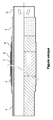
- a cold shrinkable adapter for joining or termination of electrical cables insulated by paper comprising a set of insulating or conductive layers and an outer protective sleeve 5.
- a tubular support member 3 keeps the set of layers in a radially expanded state, which support member can be removed from this assembly to provide for the retraction of the layers on the cable or cables of the termination or junction.
- the set of layers comprises an insulating sleeve 1, advantageously of silicone rubber, a conductive metal element 4 preferably consisting of a sock of copper wires and a semiconductor layer 2 advantageously of semi-conductive silicone rubber situated between the insulating sleeve 3 and the conductive metal element 4.
- a metallized sheet 6 is disposed between the conductive metal element and the outer protective sleeve, over a length greater than that of the outer protective sleeve 5, this sheet protruding at each end of this sleeve 5.
- a moisture-absorbing swelling layer 7 is disposed between the set of layers and the metallized sheet 6. This layer 7 is of length less than the length of the metallized sheet and is completely covered by the latter.
- the metallized sheet 6 and the swelling layer 7 may be formed of a strip wound one after the other around the set of layers.
- the swelling layer 7 is made of a fiber ribbon encapsulating swelling gel particles. It can be used polyester fibers and polyacrylate particles.
- the adapter For installation on the cable, the adapter is slid on this cable and by removal of a tube of the support member 3, the entire assembly of layers retracts against the cable, as already described in the document patent EP 1 220 408 .
- the conductive metal element 4 At each end of the protective sleeve 5, the conductive metal element 4 is apparent to allow electrical contacts to be made.
- the adapter being seen in the direction of the figure, the free left end of the conductive metal element 4 and the metallized sheet 6 are folded over the protective sleeve 5.
- L support member 3 is then translated over the cable, so that the left end of the insulating sleeve 1 is positioned as close as possible to the place where the conductor or the conductors are stripped of their common sheath, a common place called cable bun.
- the support member 3 is then pulled to the right under the insulating sleeve 1 by means of a hook adapted in the orifices provided at its right end.
- the set of layers retracts on the cable conductor and transforms the insulated conductor into paper into a polymer insulated cable, referred to as a dry cable.
- the left end of the conductive metal element 4 and the left end of the metallized sheet 6 are then unfolded, the conductive metal element 4 coming over the lead screen so as to be brought into contact with the latter, thus ensuring the continuity of the cable shielding.
- the conductive metal elements 4 are interconnected to the metal shield of the cable and a trifurcation glove is installed above the area of the bun.
- the fingers of this glove partially cover the left end of the outer protective sleeve 5.
- the free end of the conductive metal elements 4 and that of the metallized sheet 6 are then folded over the right end of the outer protective sleeve.
- the end of the insulating sleeve 1 and that of the semiconductor layer 2 are exposed over a certain length.
Landscapes
- Cable Accessories (AREA)
Applications Claiming Priority (1)
| Application Number | Priority Date | Filing Date | Title |
|---|---|---|---|
| FR0651208A FR2899733B1 (fr) | 2006-04-05 | 2006-04-05 | Adaptateur de cable, tubulaire pour la jonction ou la terminaison d'un cable moyenne tension |
Publications (2)
| Publication Number | Publication Date |
|---|---|
| EP1843442A2 true EP1843442A2 (de) | 2007-10-10 |
| EP1843442A3 EP1843442A3 (de) | 2011-04-06 |
Family
ID=37216138
Family Applications (1)
| Application Number | Title | Priority Date | Filing Date |
|---|---|---|---|
| EP07300893A Withdrawn EP1843442A3 (de) | 2006-04-05 | 2007-03-22 | Rohrförmiger Kabeladapter zur Verbindung oder zum Abschluss eines Mittelspannungskabels |
Country Status (3)
| Country | Link |
|---|---|
| US (1) | US7498515B2 (de) |
| EP (1) | EP1843442A3 (de) |
| FR (1) | FR2899733B1 (de) |
Cited By (2)
| Publication number | Priority date | Publication date | Assignee | Title |
|---|---|---|---|---|
| WO2009098131A1 (en) * | 2008-02-04 | 2009-08-13 | Tyco Electronics Raychem Gmbh | External sleeve |
| WO2012083986A1 (en) * | 2010-12-22 | 2012-06-28 | Prysmian S.P.A. | Screen connector for electrical cables and jointing assembly comprising said screen connector |
Families Citing this family (6)
| Publication number | Priority date | Publication date | Assignee | Title |
|---|---|---|---|---|
| DE102008033157B3 (de) * | 2008-07-15 | 2010-03-25 | Tyco Electronics Raychem Gmbh | Stabilisiertes Trägerelement für eine elastische Hülse, Bausatz und Montageverfahren |
| EP2711938B1 (de) * | 2012-09-25 | 2014-11-26 | Nexans | Mehrschichtige Silikonisolierung für Elektrokabel |
| CN104734106B (zh) * | 2013-12-19 | 2018-03-23 | 泰科电子(上海)有限公司 | 将冷缩式终端安装在电力电缆上的方法和冷缩式终端组件 |
| US9504195B2 (en) * | 2014-05-16 | 2016-11-22 | Tyco Electronics Corporation | Cover assemblies, kits and methods for covering electrical cables and connections |
| CN106300215A (zh) * | 2016-09-22 | 2017-01-04 | 国网山东省电力公司莱芜供电公司 | 新型便携式电缆截面密封装置 |
| EP3545596B1 (de) | 2016-11-22 | 2021-05-26 | TE Connectivity Corporation | Umschliessungen von kabeln und elektrische verbindungen sowie vorgedehnte einheit und verfahren mit denselben |
Family Cites Families (7)
| Publication number | Priority date | Publication date | Assignee | Title |
|---|---|---|---|---|
| US3564110A (en) * | 1966-12-06 | 1971-02-16 | Bell Telephone Labor Inc | Electrical cables |
| GB1569454A (en) * | 1976-08-18 | 1980-06-18 | Electric Power Res Inst | Electric cables |
| DE69610400T2 (de) * | 1995-12-23 | 2001-05-17 | Minnesota Mining And Mfg. Co., Saint Paul | Universeller Kabeladapter, mit Hilfe des Adapters hergestellte Kabelverbindung sowie Verfahren zur Herstellung derselben |
| US5844170A (en) * | 1996-03-01 | 1998-12-01 | Minnesota Mining And Manufacturing Company | Closure with flowable material and reinforcing core |
| US5906952A (en) * | 1997-03-07 | 1999-05-25 | Nordlys S.A. | Single layer absorbent cable wrap |
| EP0967706A1 (de) * | 1998-06-26 | 1999-12-29 | Alcatel | Verbindung zwischen zwei elektrischen Kabeln sowie dazugehöriges Schutzelement |
| EP1220408B1 (de) * | 2000-12-20 | 2005-10-26 | Nexans | Kabeladapter |
-
2006
- 2006-04-05 FR FR0651208A patent/FR2899733B1/fr not_active Expired - Fee Related
-
2007
- 2007-03-07 US US11/715,269 patent/US7498515B2/en not_active Expired - Fee Related
- 2007-03-22 EP EP07300893A patent/EP1843442A3/de not_active Withdrawn
Cited By (6)
| Publication number | Priority date | Publication date | Assignee | Title |
|---|---|---|---|---|
| WO2009098131A1 (en) * | 2008-02-04 | 2009-08-13 | Tyco Electronics Raychem Gmbh | External sleeve |
| WO2012083986A1 (en) * | 2010-12-22 | 2012-06-28 | Prysmian S.P.A. | Screen connector for electrical cables and jointing assembly comprising said screen connector |
| CN103299500A (zh) * | 2010-12-22 | 2013-09-11 | 普睿司曼股份公司 | 用于电缆的屏蔽连接器和包括所述屏蔽连接器的接合组件 |
| RU2558669C2 (ru) * | 2010-12-22 | 2015-08-10 | Призмиан С.П.А. | Соединитель экрана для электрических кабелей и соединительная сборка, содержащая упомянутый соединитель экрана |
| AU2010366147B2 (en) * | 2010-12-22 | 2016-08-04 | Prysmian S.P.A. | Screen connector for electrical cables and jointing assembly comprising said screen connector |
| US9590410B2 (en) | 2010-12-22 | 2017-03-07 | Prysmian S.P.A. | Screen connectors for electrical cables and jointing assemblies comprising the screen connector |
Also Published As
| Publication number | Publication date |
|---|---|
| FR2899733A1 (fr) | 2007-10-12 |
| US7498515B2 (en) | 2009-03-03 |
| US20070256852A1 (en) | 2007-11-08 |
| EP1843442A3 (de) | 2011-04-06 |
| FR2899733B1 (fr) | 2008-07-04 |
Similar Documents
| Publication | Publication Date | Title |
|---|---|---|
| EP1843442A2 (de) | Rohrförmiger Kabeladapter zur Verbindung oder zum Abschluss eines Mittelspannungskabels | |
| CA2197576C (fr) | Jonction de cables de puissance | |
| JP2008108684A (ja) | シールド線のドレン線止水構造およびドレン線止水方法 | |
| EP0091633A1 (de) | Vorrichtung zum Verbinden der Enden von zwei faseroptischen Unterwasserkabeln und Verfahren zu deren Herstellung | |
| EP2193529B1 (de) | Schutzhülle gegen strahlung, insbesondere gegen strahlung aus dem von elektrischen kabeln erzeugten elektrischen feld | |
| JP5402065B2 (ja) | シールド線の端末止水方法および端末止水部を備えたシールド線 | |
| WO2016079428A1 (fr) | Capteur de température | |
| FR2503476A1 (fr) | Procede de depose d'une gaine protectrice sur l'extremite d'un cable electrique et dispositif pour la mise en oeuvre de celui-ci | |
| EP0549942B1 (de) | Verbindung von elektrischen Kabeln, vormontierter Verbindungszusammenbau und Herstellungsverfahren | |
| US6624357B2 (en) | Cable adapter | |
| EP0933856B1 (de) | Kaltschrumpfbare Dichtungsmuffe für elektrische Kabel | |
| CA2143270C (fr) | Dispositif de connexion electrique pour ecrans de cables conducteurs, et procede pour sa mise en oeuvre | |
| CA2572944C (fr) | Gaine de protection a l'egard du rayonnement, notamment du champ electrique engendre par des cables electriques | |
| FR2551927A1 (fr) | Dispositif de blindage electromagnetique de jonction | |
| EP3146350B1 (de) | Mit einer vorrichtung mit kontinuierlicher überwachung ausgestattete hochspannungs-trockenvorrichtung | |
| FR3018400A1 (fr) | Procede de protection d'un cable et gaine de protection du cable | |
| EP2750255B1 (de) | Zubehör für Niederspannungskabel | |
| JP5264130B2 (ja) | 線間止水方法 | |
| FR2720199A1 (fr) | Structure de liaison électrique d'un manchon protecteur avec une extrémité d'un écran semi-conducteur d'un câble électrique. | |
| EP1585204A1 (de) | Hochspannungsenergieübertragungssystem | |
| EA026207B1 (ru) | Устройство для сращивания кабелей в воздушной линии электропередачи среднего напряжения | |
| EP0727856A1 (de) | Halbleitendes Band für Mittel- und Hochspannungskabel und resultierendes Kabel | |
| FR2760146A1 (fr) | Manchon d'etancheite et de protection pour une extremite de cable electrique | |
| FR2981209A1 (fr) | Dispositif de raccordement d'une gaine de blindage de cable | |
| EP1037311A1 (de) | Vorrichtung zum Abdichten einer Verbindung eines flachen Geflechts |
Legal Events
| Date | Code | Title | Description |
|---|---|---|---|
| PUAI | Public reference made under article 153(3) epc to a published international application that has entered the european phase |
Free format text: ORIGINAL CODE: 0009012 |
|
| AK | Designated contracting states |
Kind code of ref document: A2 Designated state(s): AT BE BG CH CY CZ DE DK EE ES FI FR GB GR HU IE IS IT LI LT LU LV MC MT NL PL PT RO SE SI SK TR |
|
| AX | Request for extension of the european patent |
Extension state: AL BA HR MK YU |
|
| PUAL | Search report despatched |
Free format text: ORIGINAL CODE: 0009013 |
|
| AK | Designated contracting states |
Kind code of ref document: A3 Designated state(s): AT BE BG CH CY CZ DE DK EE ES FI FR GB GR HU IE IS IT LI LT LU LV MC MT NL PL PT RO SE SI SK TR |
|
| AX | Request for extension of the european patent |
Extension state: AL BA HR MK RS |
|
| AKY | No designation fees paid | ||
| REG | Reference to a national code |
Ref country code: DE Ref legal event code: R108 |
|
| REG | Reference to a national code |
Ref country code: DE Ref legal event code: R108 Effective date: 20111214 |
|
| STAA | Information on the status of an ep patent application or granted ep patent |
Free format text: STATUS: THE APPLICATION IS DEEMED TO BE WITHDRAWN |
|
| 18D | Application deemed to be withdrawn |
Effective date: 20111007 |