EP1843594A2 - Codage et décodage vidéo avec plusieurs configurations de balayage des coefficients - Google Patents
Codage et décodage vidéo avec plusieurs configurations de balayage des coefficients Download PDFInfo
- Publication number
- EP1843594A2 EP1843594A2 EP07113264A EP07113264A EP1843594A2 EP 1843594 A2 EP1843594 A2 EP 1843594A2 EP 07113264 A EP07113264 A EP 07113264A EP 07113264 A EP07113264 A EP 07113264A EP 1843594 A2 EP1843594 A2 EP 1843594A2
- Authority
- EP
- European Patent Office
- Prior art keywords
- scan pattern
- data
- nxm
- coding
- image data
- Prior art date
- Legal status (The legal status is an assumption and is not a legal conclusion. Google has not performed a legal analysis and makes no representation as to the accuracy of the status listed.)
- Withdrawn
Links
Images


Classifications
-
- H—ELECTRICITY
- H04—ELECTRIC COMMUNICATION TECHNIQUE
- H04N—PICTORIAL COMMUNICATION, e.g. TELEVISION
- H04N19/00—Methods or arrangements for coding, decoding, compressing or decompressing digital video signals
- H04N19/10—Methods or arrangements for coding, decoding, compressing or decompressing digital video signals using adaptive coding
- H04N19/169—Methods or arrangements for coding, decoding, compressing or decompressing digital video signals using adaptive coding characterised by the coding unit, i.e. the structural portion or semantic portion of the video signal being the object or the subject of the adaptive coding
- H04N19/17—Methods or arrangements for coding, decoding, compressing or decompressing digital video signals using adaptive coding characterised by the coding unit, i.e. the structural portion or semantic portion of the video signal being the object or the subject of the adaptive coding the unit being an image region, e.g. an object
- H04N19/176—Methods or arrangements for coding, decoding, compressing or decompressing digital video signals using adaptive coding characterised by the coding unit, i.e. the structural portion or semantic portion of the video signal being the object or the subject of the adaptive coding the unit being an image region, e.g. an object the region being a block, e.g. a macroblock
-
- H—ELECTRICITY
- H04—ELECTRIC COMMUNICATION TECHNIQUE
- H04N—PICTORIAL COMMUNICATION, e.g. TELEVISION
- H04N19/00—Methods or arrangements for coding, decoding, compressing or decompressing digital video signals
- H04N19/10—Methods or arrangements for coding, decoding, compressing or decompressing digital video signals using adaptive coding
- H04N19/134—Methods or arrangements for coding, decoding, compressing or decompressing digital video signals using adaptive coding characterised by the element, parameter or criterion affecting or controlling the adaptive coding
- H04N19/157—Assigned coding mode, i.e. the coding mode being predefined or preselected to be further used for selection of another element or parameter
- H04N19/16—Assigned coding mode, i.e. the coding mode being predefined or preselected to be further used for selection of another element or parameter for a given display mode, e.g. for interlaced or progressive display mode
-
- H—ELECTRICITY
- H04—ELECTRIC COMMUNICATION TECHNIQUE
- H04N—PICTORIAL COMMUNICATION, e.g. TELEVISION
- H04N19/00—Methods or arrangements for coding, decoding, compressing or decompressing digital video signals
- H04N19/10—Methods or arrangements for coding, decoding, compressing or decompressing digital video signals using adaptive coding
- H04N19/102—Methods or arrangements for coding, decoding, compressing or decompressing digital video signals using adaptive coding characterised by the element, parameter or selection affected or controlled by the adaptive coding
- H04N19/129—Scanning of coding units, e.g. zig-zag scan of transform coefficients or flexible macroblock ordering [FMO]
-
- H—ELECTRICITY
- H04—ELECTRIC COMMUNICATION TECHNIQUE
- H04N—PICTORIAL COMMUNICATION, e.g. TELEVISION
- H04N19/00—Methods or arrangements for coding, decoding, compressing or decompressing digital video signals
- H04N19/10—Methods or arrangements for coding, decoding, compressing or decompressing digital video signals using adaptive coding
- H04N19/169—Methods or arrangements for coding, decoding, compressing or decompressing digital video signals using adaptive coding characterised by the coding unit, i.e. the structural portion or semantic portion of the video signal being the object or the subject of the adaptive coding
- H04N19/17—Methods or arrangements for coding, decoding, compressing or decompressing digital video signals using adaptive coding characterised by the coding unit, i.e. the structural portion or semantic portion of the video signal being the object or the subject of the adaptive coding the unit being an image region, e.g. an object
- H04N19/172—Methods or arrangements for coding, decoding, compressing or decompressing digital video signals using adaptive coding characterised by the coding unit, i.e. the structural portion or semantic portion of the video signal being the object or the subject of the adaptive coding the unit being an image region, e.g. an object the region being a picture, frame or field
-
- H—ELECTRICITY
- H04—ELECTRIC COMMUNICATION TECHNIQUE
- H04N—PICTORIAL COMMUNICATION, e.g. TELEVISION
- H04N19/00—Methods or arrangements for coding, decoding, compressing or decompressing digital video signals
- H04N19/46—Embedding additional information in the video signal during the compression process
-
- H—ELECTRICITY
- H04—ELECTRIC COMMUNICATION TECHNIQUE
- H04N—PICTORIAL COMMUNICATION, e.g. TELEVISION
- H04N19/00—Methods or arrangements for coding, decoding, compressing or decompressing digital video signals
- H04N19/60—Methods or arrangements for coding, decoding, compressing or decompressing digital video signals using transform coding
- H04N19/61—Methods or arrangements for coding, decoding, compressing or decompressing digital video signals using transform coding in combination with predictive coding
Definitions
- the present invention relates to a method and apparatus for coding and decoding image data. More specifically, embodiments of the present invention relate to a coding and decoding method and apparatus using a plurality of scanning patterns.
- ITU-T International Telecommunication Union
- ISO/IEC International Telecommunication Union
- next generation technology considers not only the progressive but also interlaced scanned images.
- coding efficiencies can be lowered, because image producing methods for the progressive and the interlaced scanned images are different, and accordingly, characteristics of the coding image data are different from each other.
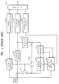
- FIG. 1 A conventional coding apparatus is shown in FIG. 1 as a block diagram.
- the coding apparatus includes a coding controller 100, a first source encoder 200, a second source encoder 700, a first source decoder 300, a memory 400, a motion compensation unit 500, and a motion prediction unit 600.
- the coding controller 100 determines whether to implement motion compensation for the input image, i.e., a coding type, according to the characteristic of the input image or an objective of motion that a user wishes to obtain, and outputs a corresponding control signal to a first switch S10.
- motion compensation the first switch S10 turns on, because a previous or a following input image is needed. If the motion compensation is not required, the first switch S10 turns off, because the previous or the following input image is not needed. If the first switch S10 turns on, differential image data between the input image and the previous image is provided to the first source encoder 200. If the first switch S10 turns off, the input image data is provided to the first source encoder 200.
- the first source encoder 200 transforms the input image data to produce transformation coefficients, and quantizes the transformation coefficients to produce NxM data according to a predetermined quantization process.
- DCT discrete cosine transformation
- the input image data received by and coded through the first source encoder 200 can be used as reference data for motion compensation of a following or a previous input image data. Therefore, such coded input image data is inversely quantized and transformed through the first source decoder 300 that processes data inversely to the first source encoder 200 and then stored in the memory 400. If the data provided to the memory 400 through the first source decoder 300 is the differential image data, the coding controller 100 turns on a second switch S20 so that the differential image data is added to an output of the motion compensation unit 500 and then stored in the memory 400.
- the motion prediction unit 600 compares the input image data with the data stored in the memory 400, and searches for data that mostly approximate the input image data provided at present. After comparing the searched data with the input image data, the motion prediction unit 600 outputs a motion vector. When the motion vector is provided to the memory 400, the memory 400 outputs corresponding data to the motion compensation unit 500. Based on the data provided from the memory 400, the motion compensation unit 500 produces a compensation value corresponding to the presently coding image data.
- the second source encoder 700 encodes and outputs the quantized transformation coefficients provided from the first source encoder 200.
- a motion vector encoder 900 receives information on the motion vector from the motion prediction unit 600, and encodes and outputs such information.
- a coding information encoder 800 receives coding type information, quantization information, and other information required for decoding from the coding controller 100, and encodes and outputs such information.
- a multiplexer 1000 multiplexes outputs of the second source encoder 700, the coding information encoder 800, and the motion vector encoder 900, and outputs an ultimate bit stream.
- the conventional coding apparatus as described above generally utilizes a coding method of dividing the input image data by a predetermined size and coding in a unit of a macro block.
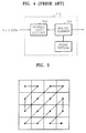
- FIG. 2 is a more specific block diagram of the second source encoder 700 shown in FIG. 1.
- the second source encoder 700 includes a scanner 701 and a variable length encoder 702.
- the scanner 701 receives the NxM data comprised of the quantized transformation coefficients, and scans the NxM data in a zigzag pattern as shown in FIG. 5.
- the variable length encoder 702 encodes the scanned data in variable length.
- FIG. 3 is a block diagram of a decoding apparatus for decoding the data coded by the coding apparatus shown in FIG. 1.
- the decoding apparatus includes a demultiplexer 110, a second source decoder 710, a first source decoder 210, a coding type information interpreter 120, and a motion vector interpreter 130.
- the demultiplexer 110 demultiplexes the bit stream into entropy-coded and quantized transformation coefficients, motion vector information, coding type information, etc.
- the second source decoder 710 entropy-decodes the coded transformation coefficients and outputs quantized transformation coefficients.
- the first source decoder 210 source-decodes the quantized transformation coefficients. That is, the first source decoder 210 processes data inversely to the first source encoder 200. For example, if the first source encoder 200 performs the discrete cosine transformation (DCT), the first source decoder 210 performs inverse discrete cosine transformation (IDCT). Consequently, the image data is recovered. Then, the reconstructed image data is stored in a memory 410 for motion compensation.
- DCT discrete cosine transformation
- IDCT inverse discrete cosine transformation
- the coding type information interpreter 120 discriminates the coding type. If the coding type is an inter type that requires motion compensation, the coding type information interpreter 120 turns on a third switch S30 so that a motion compensation value provided from a motion compensation unit 510 is added to the data provided from the first source decoder 210 to produce the reconstructed image data.
- the motion vector interpreter 130 indicates a location directed by the motion vector obtained from the motion vector information, and the motion compensation unit 510 produces a motion compensation value from the reference image data directed by the motion vector.
- FIG. 4 is a more specific block diagram of the second source decoder 710 shown in FIG. 3.
- the second source decoder 710 includes a variable length decoder 703 and an inverse scanner 704.
- the second source decoder 710 processes data inversely to the second source encoder 700 shown in FIG. 2.
- the variable length decoder 703 decodes the quantized transformation coefficients that are coded in variable length, and recovers the NxM data.
- the inverse scanner 704 inversely scans the NxM data using the zigzag scan pattern as shown in FIG. 5.
- the conventional coding and decoding apparatus as described above may cause problems in case of coding or decoding interlaced scanned images. Since there exists a time difference between the fields, the image can be altered even in adjacent fields. The problem is very serious in case of an image having relatively much motion. Particularly, in case of coding the interlaced scanned images in a unit of a frame, not in a unit of a field, i.e., if a picture format that is a unit for coding is an interlaced scanned frame format, locations of objects included in the image can be changed in accordance with top and bottom field data, and accordingly, the outlines of the objects can be distorted and the characteristics of the data can be considerably changed in a vertical direction.
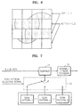
- FIG. 6 shows an example of an image data having an interlaced scanning frame format.
- data existing in first, third, or other odd columns of the image data forming an NxM block is the image data from the top field of the interlaced scanned image
- data existing in second, fourth, or other even columns is the image data from the bottom field. If there is a time difference between the top and the bottom fields, and if the motion corresponding to the time difference is great, an identical object is formed with incorrectly arranged images in a vertical direction. In case of transforming and coding such data, high frequency components increase in a vertical direction, and therefore, non-zero transformation coefficients occasionally appear even in lower columns of the NxM block that is comprised of the transformation coefficients.
- the conventional coding technology has a problem in that the maximal coding efficiency for the image data having various characteristics is not achieved because a single scan pattern is used for scanning the image.
- the present invention provides a coding and decoding method and apparatus, which can improve coding efficiency of image data having various characteristics.
- the present invention also provides a coding and decoding method and apparatus, which can improve coding efficiency of image data having an interlaced scanned image frame format.
- the present invention also provides a coding and decoding method and apparatus, which can improve coding efficiency of image data having relatively much motion and relatively much variation in a vertical direction.
- a coding method of image data including : (a) obtaining NxM data by firstly source-coding the image data; (b) scanning the NxM data using a predetermined scan pattern selected from a plurality of scan patterns in response to the obtained NxM data; and (c) secondly source-coding the scanned data.
- a coding method of image data including: (a) obtaining NxM data by firstly source-coding the image data; (b) dividing the obtained NxM data into a plurality of areas; (c) scanning the NxM data using predetermined scan patterns respectively selected from a plurality of scan patterns in response to the divided areas; and (d) secondly source-coding the scanned data.
- Step (a) includes :(a1) transforming the image data; and (a2) quantizing the transformed image data to produce the NxM data.
- Step (c) includes :(c1) selecting a scan pattern that scans an area having more substantially zero component values later than the other areas of the NxM data; and (c2) scanning the NxM data using the selected scan pattern.
- step (b) includes :(b1) horizontally dividing the NxM data to produce at least two sub-areas, (b2) vertically dividing the NxM data to produce at least two sub-areas, or (b3) horizontally and vertically dividing the NxM data to produce at least four sub-areas.
- a decoding method of image data including: (a) producing scan pattern selection information to select a predetermined scan pattern among a plurality of scan patterns; (b) inversely scanning the image data that is variable-length-decoded to obtain NxM data using at least one scan pattern selected on the basis of the scan pattern selection information; and (c) source-decoding the NxM data.
- step (c) includes:(c1) inversely quantizing the NxM data; and (c2) inversely transforming and decoding the inversely quantized NxM data.
- a decoding method of image data including: (a) variable-length-decoding the image data; (b) inversely scanning the image data variable-length-decoded to obtain NxM data using at least one scan pattern selected from a plurality of scan patterns; and (c) source-decoding the NxM data.
- step (b) includes :(b11) selecting a scan pattern that scans an area having more substantially zero component values later than the other areas of the NxM data; and (b2) inversely scanning the NxM data using the selected scan pattern.
- step (b) includes :(b21) selecting a scan pattern that scans horizontal high frequency component values relatively earlier than vertical high frequency component values in the event that the NxM data is based on the image data having an interlaced scanned frame format; and (b2) inversely scanning the NxM data using the selected scan pattern.
- step (b) includes: (b22) selecting a scan pattern that scans horizontal high frequency component values and vertical high frequency component values in a substantially equal order in the event that the NxM data is based on the image data having an interlaced scanned field format or progressive scanned frame format ; and (b2) inversely scanning the NxM data using the selected scan pattern.
- step (b) includes:(b31) selecting a scan pattern corresponding to a macro block type of the NxM data; and (b2) inversely scanning the NxM data using the selected scan pattern.
- step (b) includes:(b41) selecting a scan pattern corresponding to a picture format and a macro block type of the NxM data; and (b2) inversely scanning the NxM data using the selected scan pattern.
- step (a) includes:(a1) transforming code words that constitute the image data into predetermined symbol data.
- a decoding method of image data including: (a) obtaining symbol data by variable-length-decoding the image data; (b) obtaining transformation coefficients from the symbol data; (c) producing scan pattern selection information to select a predetermined scan pattern among a plurality of scan patterns; (d) inversely scanning the transformation coefficients to obtain NxM data using the scan pattern based on the scan pattern selection information; and (e) source-decoding the inversely scanned data.
- step (c) includes :(c1) analyzing the received picture format information; and(c21) selecting a scan pattern that scans horizontal high frequency component values relatively earlier than vertical high frequency component values in the event that the result of analyzing is that the received picture format is an interlaced scanned frame format or(c1) analyzing the received picture format information; and (c22) selecting a scan pattern that scans horizontal high frequency component values and vertical high frequency component values in a substantially equal order in the event that the result of analyzing is that the received picture format is an interlaced scanned field format or progressive scanned frame format.
- a coding apparatus of image data including a first encoder, a coding controller, and a second encoder.
- the first encoder firstly encodes the image data to produce NxM data.
- the coding controller produces scan pattern selection information used to select a predetermined scan pattern in response to NxM data.
- the second encoder scans the NxM data with the scan pattern based on the scan pattern selection information and secondly encoding the NxM data.
- the first encoder includes a transformer that transforms and encodes the image data, and a quantizer that quantizes the data transformed by the transformer and produces the NxM data.
- a decoding apparatus of image data including a second decoder, a scan pattern selector, and an inverse scanner.
- the second decoder decodes the image data to produce transformation coefficients.
- the scan pattern selector produces a scan pattern selection information to select a predetermined scan pattern among a plurality of scan patterns.
- the inverse scanner inversely scans the transformation coefficients to NxM data using the scan pattern based on the scan pattern selection information.
- FIG. 7 A preferred embodiment of an encoder according to the present invention is shown in FIG. 7.
- the encoder is for secondly source-coding and includes a scanner 71 and a variable length encoder 72.
- a switch 73 shown in FIG. 7 selects at least one scan pattern among a plurality of scan patterns NxM according to a scan pattern selection signal provided from outside.
- the scan pattern selection signal is provided from a coding controller (not shown in FIG. 7).
- the scan pattern means reference information to determine an order to read NxM data.
- the scanner 71 scans the NxM data provided from outside using at least one scan pattern selected by the switch 73 on the basis of the scan pattern selection signal. In other words, the scanner 71 reads the NxM data in a predetermined order and transforms it into symbol data.
- the variable length encoder 72 encodes in variable length the scanned data, i.e., the symbol data.
- the NxM data in the preferred embodiment of the present invention means block data obtained by firstly source-coding the image data.
- the term 'firstly source-coding' means transforming two-dimensional image data having a plurality of pixel values into data in another domain.
- the image data comprised of pixel values is transformed into data in the frequency domain through a discrete cosine transformation (DCT).
- DCT discrete cosine transformation
- the symbol data in the preferred embodiment of the present invention means run-level data obtained as a result of scanning the NxM data with the predetermined scan pattern.
- the run-level data may be one-dimensional (1 D) data in which a run value and a level value are divided from each other, two-dimensional (2D) data in which the run value and the level value are paired, or three-dimensional data (3D) comprised of a last value, a run value, and a level value.
- the variable length encoder 72 encodes the 2D run-level data into corresponding code words (Run, Level), or encodes the 1 D run-level data in which run components and level components are divided from each other into corresponding code words (1 D variable length encoding). It is also possible to implement 3D variable length encoding for encoding the 3D run-level data (Last, Run, Level) into corresponding code words.
- the variable length encoder 72 may utilize a Huffman encoder or an arithmetic encoder.
- the coding controller selects a scan pattern according to a predetermined scan pattern selection logic, and provides the scan pattern selection information corresponding to the selected scan pattern to the switch 73.
- the coding controller may provide scan pattern selection information to select the scan pattern that reads an area having more substantially zero values later than the other area of the NxM data.
- the coding controller provides such scan pattern selection information that selects the scan pattern to read horizontal high frequency component values relatively earlier than vertical high frequency component values in comparing with a zigzag pattern.
- the coding controller provides suitable scan pattern selection information that selects the scan pattern to read the vertical and horizontal high frequency component values in a substantially equal order.
- the coding controller may provide scan pattern selection information to select a scan pattern corresponding to a macroblock type of the NxM data, or provide scan pattern selection information to select a scan pattern corresponding to a picture format and a macro block type of the NxM data. Further, the coding controller may produce scan pattern selection information to select different scan patterns for at least two sub-areas obtained by horizontally dividing the NxM data or to select different scan patterns for at least two sub-areas obtained by vertically dividing the NxM data, or may produce scan pattern selection information to select different scan patterns for at least four sub-areas obtained by vertically and horizontally dividing the NxM data. Moreover, it is also possible to arbitrarily divide the NxM data area into at least two sub-areas and to provide scan pattern selection information to select different scan patterns for each of such sub-areas.
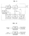
- FIG. 8 is a block diagram of a coding apparatus for coding image data according to a preferred embodiment of the present invention. As to the blocks having identical functions to the blocks described with reference to FIG. 7, the same reference numerals are used in FIG. 8 and redundant descriptions thereof are omitted below.
- the coding apparatus includes a first source encoder 2 for source-coding the image data to obtain NxM data, a coding controller 1 for providing scan pattern selection information to inform a scan pattern selected from a plurality of scan patterns, and a second source encoder 7 for scanning the NxM data using the selected scan pattern on the basis of the scan pattern selection information so that each of the NxM data corresponds to each of sub-areas when the NxM data is divided into a plurality of sub-areas, and for entropy-coding the scanned data.
- the coding apparatus includes a first source decoder 3, a memory 4, a motion compensation unit 5, a motion prediction unit 6, a coding information encoder 8, a motion vector encoder 9, and a multiplexer 10.
- Input image data is comprised of frames to be provided from a camera at a predetermined frame rate, or blocks to be obtained by dividing the frames by a predetermined size.
- the frame includes a progressive scanned frame obtained through progressive scanning, and an interlaced scanned field or frame obtained through interlaced scanning. Therefore, the image data described below means a picture having a progressive scanned frame format, interlaced frame format, field format, or block format.
- the coding controller 1 determines a coding type, i.e., an intra-coding type or an inter-coding type, based on whether to implement motion compensation for the input image according to the characteristic of the input image or an objective of motion that a user wishes to obtain, and outputs a corresponding control signal to a first switchS1.
- a coding type i.e., an intra-coding type or an inter-coding type
- the first switch S1 turns on, because a previous or a following input image is needed. If motion compensation is not required, the first switch S1 turns off, because the previous or the following input image is not needed. If the first switch S1 turns on, differential image data between the input image and the previous image is provided to the first source encoder 2. If the first switch S1 turns off, the input image data is provided to the first source encoder 2.
- the coding controller 1 provides scan pattern selection information to the second source encoder 7.
- the scan pattern selection information is the same information as already described with reference to FIG. 7.
- the coding controller 1 transfers the scan pattern selection information to a transmitter (not shown) or stores the information, if necessary.
- the first source encoder 2 quantizes transformation coefficients obtained by transforming the input image data according to a predetermined quantization process to produce NxM data that is two-dimensional data comprised of the quantized transformation coefficients.
- a discrete cosine transformation may be used.
- the quantization is performed according to a predetermined quantization process.
- the input image data coded through the first source encoder 2 can be used as reference data for motion compensation of a following or a previous input image data. Therefore, such coded input image data is inversely quantized and transformed through the first source decoder 3 that processes data inversely to the first source encoder 2 and, then, stored in the memory 4. If the data provided to the memory 4 through the first source decoder 3 is the differential image data, the coding controller 1 turns on a second switch S2 so that the differential image data is added to an output of the motion compensation unit 5 and, then, stored in the memory 4.
- the motion prediction unit 6 compares the input image data with the data stored in the memory 4, and searches for data that most closely approximates the input image data provided at present. After comparing the searched data with the input image data provided at present, the motion prediction unit 6 outputs a motion vector (MV).
- the motion vector is obtained with reference to at least one picture. In other words, the motion vector can be produced with reference to a plurality of previous and/or following pictures.
- the memory 4 outputs corresponding data to the motion compensation unit 5. Based on the data provided from the memory 4, the motion compensation unit 5 produces a compensation value corresponding to the presently coding image data.
- the second source encoder 7 receives the quantized transformation coefficients from the first source encoder 2 and entropy-encodes the NxM data after scanning the NxM data with a scan pattern selected on the basis of the scan pattern selection information provided from the coding controller 1.
- the motion vector encoder 9 receives information on the motion vector from the motion prediction unit 6, and encodes and outputs such information.
- the coding information encoder 8 receives coding type information, quantization information, and other information required for decoding from the coding controller 1, and encodes and outputs such information.
- the multiplexer 10 multiplexes outputs of the second source encoder 7, the coding information encoder 8 and the motion vector encoder 9, and outputs an ultimate bit stream.
- FIG. 9 is a block diagram of a decoding apparatus according to a preferred embodiment of the present invention.
- the decoding apparatus comprises an inverse scanner 91, a variable length decoder 92, and a scan pattern selector 93.
- a switch 94 shown in FIG. 9 selects at least one scan pattern among a plurality of scan patterns NxM according to the scan pattern selection information provided from the scan pattern selector 93.
- the variable length decoder 92 variable-length-decodes the input bit stream and transforms the input bit stream into symbol data.
- the inverse scanner 91 inversely scans the symbol data using at least one scan pattern selected by the switch 94 on the basis of the scan pattern selection information, and restructures the NxM data. Consequently, the NxM data is obtained as first source-coded block data.
- the symbol data in the present embodiment means run-level data.
- the variable length decoder 92 decodes predetermined code words included in the bit stream to obtain corresponding run-level data.
- the scan pattern selector 93 operates on a predetermined scan pattern selection logic, and self-produces scan pattern selection information to be provided to the switch 94. It is noted that the characteristic of the scan pattern will be described on the basis of a coding process for convenience of the description.
- the scan pattern selector 93 may produce scan pattern selection information to select the scan pattern that reads an area having more substantially zero values later among the NxM data to be restructured.
- the scan pattern selector 93 produces such scan pattern selection information that selects the scan pattern to read horizontal high frequency component values relatively earlier than vertical high frequency component values in comparing with a zigzag pattern.
- the scan pattern selector 93 produces appropriate scan pattern selection information that selects the scan pattern to read the vertical and horizontal high frequency component values in a substantially equal order.
- the scan pattern selector 93 may provide scan pattern selection information to select a scan pattern corresponding to a macro block type of the NxM data to be restructured, or provide scan pattern selection information to select a scan pattern corresponding to a picture format and a macro block type of the NxM data to be restructured.
- the scan pattern selector 93 may produce scan pattern selection information to select different scan patterns for at least two sub-areas obtained by horizontally dividing the NxM data to be restructured or to select different scan patterns for at least two sub-areas obtained by vertically dividing the NxM data to be restructured, or may produce scan pattern selection information to select different scan patterns for at least four sub-areas obtained by vertically and horizontally dividing the NxM data to be restructured.
- the information representing whether a coding unit of the input image data during the coding process is a frame format or a field format, or whether the input image data is a progressive scanned image or an interlaced scanned image, i.e., picture format information representing the picture format of the input image data or macro block type information representing the macro block type should be necessarily transferred to the decoding apparatus. Therefore, if the scan pattern selection logic is predetermined to select a predetermined scan pattern on the basis of such information, it is advantageous to select a scan pattern without sending information to select the scan pattern from the coding apparatus to the decoding apparatus.
- FIGS. 10 to 12 show embodiments of the scan pattern selector 93 shown in FIG. 9.
- the scan pattern selector 93 receives picture format information and produces corresponding scan pattern selection information in accordance with the scan pattern selection logic, or receives macro block type information and produces corresponding scan pattern selection information.
- the scan pattern selector 93 receives picture format information and macro block type information, and produces corresponding scan pattern selection information in accordance with the scan pattern selection logic.
- the scan pattern selector 93 receives a plurality of coding information NxM, and produces corresponding scan pattern selection information in accordance with the scan pattern selection logic.
- the coding information mentioned above is conditional information for coding, which is provided from a transmitter to the decoding apparatus for decoding.
- the scan pattern selection logic may be implemented in a predetermined mapping table.
- the mapping table may include mapping information in which a predetermined scan pattern is mapped with respect to predetermined coding information. For example, a scan pattern corresponding to macro block type information, picture format information, or the like can be mapped.
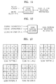
- FIGS. 13 to 15 show scan patterns according to an embodiment of the present invention, which can be used by the coding apparatus or the decoding apparatus described above with reference to FIGS. 7 to 9.
- the coding controller 1 of the coding apparatus or the scan pattern selector 93 of the decoding apparatus may select the scan pattern 4 representing a case where the probability of horizontal high frequency component values becoming zeroes is lower than the probability of vertical high frequency component values becoming zeroes in the event that the picture format is the interlaced scanned frame format. Otherwise, the scan pattern 3 may be selected.
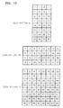
- FIGS. 16 and 17 show scan patterns according to another embodiment of the present invention.
- scan patterns that scan a plurality of NxM blocks simultaneously by rendering a plurality of NxM data as a block.
- component values of a plurality of NxM data 1, 2,3,4 are rendered as component values of the scanning NxM data.
- the number and size of the NxM data to be rendered as a block can be determined variously upon requirements, and the scanning order therefor can be correspondingly adjusted.
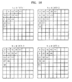
- FIGS. 18 to 21 show dividing modes for using a plurality of scanning patterns according to preferred embodiments of the present invention.
- FIGS. 18 to 21 there are shown modes for dividing the NxM data so that the coding apparatus or the decoding apparatus described above with reference to FIGS. 7 to 9 can use a plurality of scan patterns.
- the coding controller 1 of the coding apparatus or the scan pattern selector 93 of the decoding apparatus may produce scan pattern selection information to select different scan patterns for at least two sub-areas obtained by horizontally dividing the NxM data as shown in FIG. 16 or by vertically dividing the NxM data as shown in FIG.
- the scan pattern selector 93 of the decoding apparatus may receive scan pattern selection information provided from the coding apparatus or read the scan pattern selection information stored in the coding apparatus, and produce scan pattern selection information on the basis of such received or read information.
- the above-described coding method and decoding method can be applied to multidimensional data without substantial modifications or changes. Further, the above-described coding method and decoding method can be incorporated into a computer program. A computer programmer in the field of the present invention may easily write the codes or code segments to constitute the computer program. Further, the program can be stored in a computer readable information-recoding medium, and can be read and implemented to realize the coding method and decoding method.
- the computer readable information-recoding medium includes magnetic recording medium, optical recording medium, and carrier wave medium.
- coding and decoding image data having various characteristics can be implemented efficiently. Particularly, even for the image data having an interlaced scanning frame format, more efficient coding and decoding can be achieved. Moreover, coding efficiencies for the images having relatively much motion or relatively much variation in a vertical direction can be improved.
- the present invention can be widely applied to a variety of fields including real time interactive applications such as videophones, audio/video communications through a mobile network, video application services through the Internet, video transmission for sign language or lip-reading communication, video storage and retrieval for video on demand services, video storage and transmission application for video mails, multi-location communication through heterogeneous network, digital broadcasting, etc.
- real time interactive applications such as videophones, audio/video communications through a mobile network, video application services through the Internet, video transmission for sign language or lip-reading communication, video storage and retrieval for video on demand services, video storage and transmission application for video mails, multi-location communication through heterogeneous network, digital broadcasting, etc.
Landscapes
- Engineering & Computer Science (AREA)
- Multimedia (AREA)
- Signal Processing (AREA)
- Compression Or Coding Systems Of Tv Signals (AREA)
- Compression, Expansion, Code Conversion, And Decoders (AREA)
Applications Claiming Priority (2)
| Application Number | Priority Date | Filing Date | Title |
|---|---|---|---|
| KR1020020041797A KR100846778B1 (ko) | 2002-07-16 | 2002-07-16 | 복수개의 주사 패턴을 이용한 부호화 방법, 복호화 방법,및 그 장치 |
| EP03764227A EP1522192A4 (fr) | 2002-07-16 | 2003-06-25 | Procede et appareil de codage et decodage utilisant plusieurs parcours de balayage |
Related Parent Applications (1)
| Application Number | Title | Priority Date | Filing Date |
|---|---|---|---|
| EP03764227A Division EP1522192A4 (fr) | 2002-07-16 | 2003-06-25 | Procede et appareil de codage et decodage utilisant plusieurs parcours de balayage |
Publications (2)
| Publication Number | Publication Date |
|---|---|
| EP1843594A2 true EP1843594A2 (fr) | 2007-10-10 |
| EP1843594A3 EP1843594A3 (fr) | 2009-09-02 |
Family
ID=30113192
Family Applications (2)
| Application Number | Title | Priority Date | Filing Date |
|---|---|---|---|
| EP07113264A Withdrawn EP1843594A3 (fr) | 2002-07-16 | 2003-06-25 | Codage et décodage vidéo avec plusieurs configurations de balayage des coefficients |
| EP03764227A Withdrawn EP1522192A4 (fr) | 2002-07-16 | 2003-06-25 | Procede et appareil de codage et decodage utilisant plusieurs parcours de balayage |
Family Applications After (1)
| Application Number | Title | Priority Date | Filing Date |
|---|---|---|---|
| EP03764227A Withdrawn EP1522192A4 (fr) | 2002-07-16 | 2003-06-25 | Procede et appareil de codage et decodage utilisant plusieurs parcours de balayage |
Country Status (6)
| Country | Link |
|---|---|
| US (4) | US20040042669A1 (fr) |
| EP (2) | EP1843594A3 (fr) |
| KR (1) | KR100846778B1 (fr) |
| CN (1) | CN1292594C (fr) |
| AU (1) | AU2003243039A1 (fr) |
| WO (1) | WO2004008767A1 (fr) |
Families Citing this family (21)
| Publication number | Priority date | Publication date | Assignee | Title |
|---|---|---|---|---|
| ES2297083T3 (es) | 2002-09-04 | 2008-05-01 | Microsoft Corporation | Codificacion entropica por adaptacion de la codificacion entre modos por longitud de ejecucion y por nivel. |
| CN100496128C (zh) * | 2004-06-16 | 2009-06-03 | 浙江大学 | 视频或图像压缩中扫描变换系数的方法和装置 |
| CN101501998A (zh) * | 2006-08-04 | 2009-08-05 | 汤姆逊许可公司 | 用于对图片序列进行编码的方法以及执行所述方法的装置 |
| US8179974B2 (en) * | 2008-05-02 | 2012-05-15 | Microsoft Corporation | Multi-level representation of reordered transform coefficients |
| US8406307B2 (en) | 2008-08-22 | 2013-03-26 | Microsoft Corporation | Entropy coding/decoding of hierarchically organized data |
| KR101658585B1 (ko) * | 2009-11-05 | 2016-09-21 | 에스케이텔레콤 주식회사 | 툴 셋을 이용한 영상 부호화/복호화 방법 및 장치 |
| JP5488612B2 (ja) * | 2009-12-28 | 2014-05-14 | 富士通株式会社 | 動画像符号化装置および動画像復号装置 |
| CA2797047C (fr) | 2010-04-23 | 2016-09-20 | Soo Mi Oh | Appareil de codage d'image |
| KR101373814B1 (ko) | 2010-07-31 | 2014-03-18 | 엠앤케이홀딩스 주식회사 | 예측 블록 생성 장치 |
| US9609351B2 (en) | 2010-12-14 | 2017-03-28 | M&K Holdings Inc. | Apparatus for decoding a moving picture |
| US10992958B2 (en) | 2010-12-29 | 2021-04-27 | Qualcomm Incorporated | Video coding using mapped transforms and scanning modes |
| US9445093B2 (en) | 2011-06-29 | 2016-09-13 | Qualcomm Incorporated | Multiple zone scanning order for video coding |
| US10452740B2 (en) * | 2012-09-14 | 2019-10-22 | Sdl Netherlands B.V. | External content libraries |
| KR101502144B1 (ko) * | 2013-08-22 | 2015-03-12 | 주식회사 에스원 | 계수 정보를 변환하는 방법 및 장치 |
| US9305325B2 (en) | 2013-09-25 | 2016-04-05 | Apple Inc. | Neighbor context caching in block processing pipelines |
| US9299122B2 (en) | 2013-09-25 | 2016-03-29 | Apple Inc. | Neighbor context processing in block processing pipelines |
| US9270999B2 (en) | 2013-09-25 | 2016-02-23 | Apple Inc. | Delayed chroma processing in block processing pipelines |
| US9218639B2 (en) | 2013-09-27 | 2015-12-22 | Apple Inc. | Processing order in block processing pipelines |
| US9571846B2 (en) | 2013-09-27 | 2017-02-14 | Apple Inc. | Data storage and access in block processing pipelines |
| US9215472B2 (en) | 2013-09-27 | 2015-12-15 | Apple Inc. | Parallel hardware and software block processing pipelines |
| US9807410B2 (en) | 2014-07-02 | 2017-10-31 | Apple Inc. | Late-stage mode conversions in pipelined video encoders |
Family Cites Families (5)
| Publication number | Priority date | Publication date | Assignee | Title |
|---|---|---|---|---|
| US5506678A (en) * | 1992-02-24 | 1996-04-09 | Hewlett Packard Company | System for collecting weakly scattered electromagnetic radiation |
| US5714950A (en) * | 1992-07-23 | 1998-02-03 | Samsung Electronics Co., Ltd. | System for variable-length-coding and variable-length-decoding digitaldata |
| US5500678A (en) * | 1994-03-18 | 1996-03-19 | At&T Corp. | Optimized scanning of transform coefficients in video coding |
| EP0869680A3 (fr) * | 1997-04-04 | 2000-07-26 | Samsung Electronics Co., Ltd. | Méthode et appareil de décodage de symboles |
| US6426975B1 (en) * | 1997-07-25 | 2002-07-30 | Matsushita Electric Industrial Co., Ltd. | Image processing method, image processing apparatus and data recording medium |
-
2002
- 2002-07-16 KR KR1020020041797A patent/KR100846778B1/ko not_active Expired - Lifetime
-
2003
- 2003-06-20 US US10/465,819 patent/US20040042669A1/en not_active Abandoned
- 2003-06-25 WO PCT/KR2003/001242 patent/WO2004008767A1/fr not_active Ceased
- 2003-06-25 EP EP07113264A patent/EP1843594A3/fr not_active Withdrawn
- 2003-06-25 CN CN03801207.3A patent/CN1292594C/zh not_active Expired - Lifetime
- 2003-06-25 EP EP03764227A patent/EP1522192A4/fr not_active Withdrawn
- 2003-06-25 AU AU2003243039A patent/AU2003243039A1/en not_active Abandoned
-
2007
- 2007-06-22 US US11/767,407 patent/US20080025623A1/en not_active Abandoned
- 2007-06-22 US US11/767,375 patent/US20070242753A1/en not_active Abandoned
-
2009
- 2009-12-02 US US12/629,135 patent/US20100074541A1/en not_active Abandoned
Non-Patent Citations (5)
| Title |
|---|
| DANIEL LAUZON ET AL: "Performance Evaluation of MPEG-2 Video Coding for HDTV" IEEE TRANSACTIONS ON BROADCASTING, IEEE SERVICE CENTER, PISCATAWAY, NJ, US, vol. 42, no. 2, 1 June 1996 (1996-06-01), pages 88-94, XP011006033 ISSN: 0018-9316 * |
| K. SATO, T. SUZUKI, Y. YAGASAKI: "New Interlace Coding Tools" JOINT VIDEO TEAM (JVT), DOCUMENT JVT-B068, INPUT DOCUMENT (PROPOSAL) TO JVT, 29 January 2002 (2002-01-29), - 1 February 2002 (2002-02-01) pages 1-10, XP040417956 Geneva, CH * |
| L. WANG, D. BAYLON: "Alternate Coefficient Scanning Patterns for Interlaced ABT Coding" JOINT VIDEO TEAM (JVT), DOCUMENT JVT-C140R1, INPUT DOCUMENT (PROPOSAL) TO JVT, 6 May 2002 (2002-05-06), - 10 May 2002 (2002-05-10) pages 1-10, XP040418198 Fairfax, Virginia, USA * |
| VCEG: "H.26L Test Model Long-Term Number 7" JOINT VIDEO TEAM (JVT) OF ISO/IEC MPEG & ITU-T VCEG(ISO/IEC JTC1/SC29/WG11 AND ITU-T SG16 Q6), no. VCEG-M81d0, 11 May 2001 (2001-05-11), XP030003250 * |
| ZHOU M; DE LAMEILLIEURE J L; SCHAFER R: "MPEG-2 video coding with an adaptive selection of scanning path and picture structure" PROCEEDINGS OF THE SPIE, DIGITAL COMPRESSION TECHNOLOGIES AND SYSTEMS FOR VIDEO COMMUNICATIONS, vol. 2952, 7 October 1996 (1996-10-07), - 9 October 1996 (1996-10-09) pages 472-480, XP002535550 Berlin (Germany) * |
Also Published As
| Publication number | Publication date |
|---|---|
| KR100846778B1 (ko) | 2008-07-16 |
| US20040042669A1 (en) | 2004-03-04 |
| CN1292594C (zh) | 2006-12-27 |
| EP1522192A1 (fr) | 2005-04-13 |
| US20070242753A1 (en) | 2007-10-18 |
| US20100074541A1 (en) | 2010-03-25 |
| US20080025623A1 (en) | 2008-01-31 |
| EP1843594A3 (fr) | 2009-09-02 |
| CN1565129A (zh) | 2005-01-12 |
| WO2004008767A1 (fr) | 2004-01-22 |
| KR20040007139A (ko) | 2004-01-24 |
| EP1522192A4 (fr) | 2009-09-02 |
| AU2003243039A1 (en) | 2004-02-02 |
Similar Documents
| Publication | Publication Date | Title |
|---|---|---|
| US20070242753A1 (en) | Coding and decoding method and apparatus using plural scanning patterns | |
| US11729423B2 (en) | Apparatus and method for encoding and decoding moving picture using adaptive scanning | |
| KR100530681B1 (ko) | 부호화된비디오화상의송신및수신방법 | |
| US8401321B2 (en) | Method and apparatus for context adaptive binary arithmetic coding and decoding | |
| US7339506B2 (en) | Variable length coding method and variable length decoding method | |
| US8867614B2 (en) | Image coding method and image decoding method | |
| KR101654446B1 (ko) | 화상 복호 장치, 화상 부호화 장치 및 부호화 데이터의 데이터 구조 | |
| CN113508587B (zh) | 在视频编译系统中使用残差信息的视频解码方法及其设备 | |
| EP1649697B1 (fr) | Dispositifs de codage video-intra | |
| KR100732358B1 (ko) | 동화상 부호화 방법, 동화상 복호화 방법, 동화상 부호화 프로그램, 동화상 복호화 프로그램, 동화상 부호화 장치 및 동화상 복호화 장치 | |
| WO2005055607A1 (fr) | Systeme et procede de codage et de decodage d'une image au moyen d'une carte de flux binaire et support d'enregistrement correspondant | |
| KR20050007607A (ko) | 인트라 코딩에 기반한 공간 예측 | |
| CN114009029B (zh) | 图像数据编码和解码 | |
| US8189687B2 (en) | Data embedding apparatus, data extracting apparatus, data embedding method, and data extracting method | |
| CN117356092A (zh) | 用于混合特征视频比特流和解码器的系统、方法和比特流结构 | |
| JP3518733B2 (ja) | 物体単位映像信号符号化/復号化装置及び方法 | |
| EP1843595A2 (fr) | Codage et décodage vidéo avec plusieurs configurations de balayage des coefficients | |
| US20050063462A1 (en) | Visual scan method using scan table and discrete cosine transform device employing the same method | |
| US20060278725A1 (en) | Image encoding and decoding method and apparatus, and computer-readable recording medium storing program for executing the method | |
| JPH06113291A (ja) | 画像符号化及び復号化装置 | |
| CN114788276B (zh) | 图像数据编码和解码 | |
| KR20070075384A (ko) | 복수개의 주사 패턴을 이용한 부호화 방법, 복호화 방법,및 그 장치 | |
| JP2004242275A (ja) | 動画像符号化方法、動画像復号方法、動画像符号化プログラム、動画像復号プログラム、動画像符号化装置、及び動画像復号装置 |
Legal Events
| Date | Code | Title | Description |
|---|---|---|---|
| PUAI | Public reference made under article 153(3) epc to a published international application that has entered the european phase |
Free format text: ORIGINAL CODE: 0009012 |
|
| 17P | Request for examination filed |
Effective date: 20070726 |
|
| AC | Divisional application: reference to earlier application |
Ref document number: 1522192 Country of ref document: EP Kind code of ref document: P |
|
| AK | Designated contracting states |
Kind code of ref document: A2 Designated state(s): AT BE BG CH CY CZ DE DK EE ES FI FR GB GR HU IE IT LI LU MC NL PT RO SE SI SK TR |
|
| PUAL | Search report despatched |
Free format text: ORIGINAL CODE: 0009013 |
|
| AK | Designated contracting states |
Kind code of ref document: A3 Designated state(s): AT BE BG CH CY CZ DE DK EE ES FI FR GB GR HU IE IT LI LU MC NL PT RO SE SI SK TR |
|
| 17Q | First examination report despatched |
Effective date: 20091019 |
|
| AKX | Designation fees paid |
Designated state(s): AT BE BG CH CY CZ DE DK EE ES FI FR GB GR HU IE IT LI LU MC NL PT RO SE SI SK TR |
|
| RAP1 | Party data changed (applicant data changed or rights of an application transferred) |
Owner name: SAMSUNG ELECTRONICS CO., LTD. |
|
| STAA | Information on the status of an ep patent application or granted ep patent |
Free format text: STATUS: THE APPLICATION IS DEEMED TO BE WITHDRAWN |
|
| 18D | Application deemed to be withdrawn |
Effective date: 20160105 |