EP1843627B1 - Persönliche Sprachübertragungsvorrichtung - Google Patents
Persönliche Sprachübertragungsvorrichtung Download PDFInfo
- Publication number
- EP1843627B1 EP1843627B1 EP06126546.8A EP06126546A EP1843627B1 EP 1843627 B1 EP1843627 B1 EP 1843627B1 EP 06126546 A EP06126546 A EP 06126546A EP 1843627 B1 EP1843627 B1 EP 1843627B1
- Authority
- EP
- European Patent Office
- Prior art keywords
- earphone
- user
- ear
- voice
- transmitting tube
- Prior art date
- Legal status (The legal status is an assumption and is not a legal conclusion. Google has not performed a legal analysis and makes no representation as to the accuracy of the status listed.)
- Active
Links
Images







Classifications
-
- H—ELECTRICITY
- H04—ELECTRIC COMMUNICATION TECHNIQUE
- H04R—LOUDSPEAKERS, MICROPHONES, GRAMOPHONE PICK-UPS OR LIKE ACOUSTIC ELECTROMECHANICAL TRANSDUCERS; ELECTRIC HEARING AIDS; PUBLIC ADDRESS SYSTEMS
- H04R1/00—Details of transducers, loudspeakers or microphones
- H04R1/10—Earpieces; Attachments therefor ; Earphones; Monophonic headphones
- H04R1/1091—Details not provided for in groups H04R1/1008 - H04R1/1083
-
- H—ELECTRICITY
- H04—ELECTRIC COMMUNICATION TECHNIQUE
- H04R—LOUDSPEAKERS, MICROPHONES, GRAMOPHONE PICK-UPS OR LIKE ACOUSTIC ELECTROMECHANICAL TRANSDUCERS; ELECTRIC HEARING AIDS; PUBLIC ADDRESS SYSTEMS
- H04R1/00—Details of transducers, loudspeakers or microphones
- H04R1/10—Earpieces; Attachments therefor ; Earphones; Monophonic headphones
- H04R1/105—Earpiece supports, e.g. ear hooks
-
- H—ELECTRICITY
- H04—ELECTRIC COMMUNICATION TECHNIQUE
- H04R—LOUDSPEAKERS, MICROPHONES, GRAMOPHONE PICK-UPS OR LIKE ACOUSTIC ELECTROMECHANICAL TRANSDUCERS; ELECTRIC HEARING AIDS; PUBLIC ADDRESS SYSTEMS
- H04R1/00—Details of transducers, loudspeakers or microphones
- H04R1/10—Earpieces; Attachments therefor ; Earphones; Monophonic headphones
- H04R1/1058—Manufacture or assembly
-
- H—ELECTRICITY
- H04—ELECTRIC COMMUNICATION TECHNIQUE
- H04R—LOUDSPEAKERS, MICROPHONES, GRAMOPHONE PICK-UPS OR LIKE ACOUSTIC ELECTROMECHANICAL TRANSDUCERS; ELECTRIC HEARING AIDS; PUBLIC ADDRESS SYSTEMS
- H04R2201/00—Details of transducers, loudspeakers or microphones covered by H04R1/00 but not provided for in any of its subgroups
- H04R2201/02—Details casings, cabinets or mounting therein for transducers covered by H04R1/02 but not provided for in any of its subgroups
- H04R2201/023—Transducers incorporated in garment, rucksacks or the like
Definitions
- the present invention relates to a personal voice-transmitted device and, more particularly, to a personal voice-transmitted device, which allows a speaker to emit voice toward both ears of a user through the resonance of a front cavity and the transmission of a voice-transmitted tube, thereby improving the music transmission effect of existent earphones.
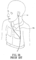
- Fig. 1 shows a prior art MP3 player 10a, which can store MP3 music files.
- the MP3 player 10a has to connect an earphone 11a.
- the earphone 11a is electrically connected to the MP3 player 10a via a transmission wire 12a.
- the user needs to place the earphone 11a into his ears to listen to MP3 music.
- the types of the earphone 11a include circumaural type, ear hook type, insert type and earplug type.
- the earphone 11a directly contacts the ears of the user, and will press the ears of the user after longtime use to cause discomfort, hence not meeting the requirement of comfort pursued by people.
- the earphone 11a directly contacts the ears, dirt and grease will accumulate on the earphone 11a to cause a sanction problem.
- the tone of the earphone 11a depends on a speaker (not shown) in the earphone 11a and the MP3 player 10a itself.
- Prior art earphones produce a near-ear tone by plugging the speaker into the ears or pressing the speaker close to the ears.
- the near-ear tone makes no use of space resonance for generating a resonance tone. Therefore, the produced tone is of low quality, and cannot be provided for the user to enjoy the sound field.
- the situation and time of use of the earphone 11a is also much restricted. For instance, when running, the earphone 11a worn on the user will easily slide. When riding a bicycle, wearing the earphone 11a will cause hesitant actions and reactions of the user, hence having a problem in safety.
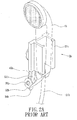
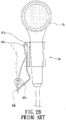
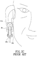
- Figs. 2A to 2C show the earphone clip structure of a prior art earphone.
- the earphone clip structure makes use of an earrings elastic plate to firmly clip on the ear.
- the earphone 1b clip structure comprises an assembly base 2b and a clip member 3b.
- groove embankments 21b at both sides form an insertion groove 22b
- embedding embankments 23b at the rear portion form an embedding groove 24b.
- the clip member 3b has an embedding plate 31b and a clip plate 33b.
- a pivotal base 32b is disposed at the bottom end of the embedding plate 31b.
- An elastic plate 34b extends from the center of the clip plate 33b.
- An extension plate 35b extends from two sides of the elastic plate 34b.
- An axial end 36b that protrudes outwardly is disposed at the bottom end of the extension plate 35b.
- the axial end 36b at two sides of the extension plate 35b can be assembled with the pivotal base 32b at the bottom of the embedding plate 31b.
- the insertion groove 22b of the assembly base 2b can be provided for the insertion assembly of an earphone 1b
- the embedding groove 24b of the assembly base 2b can be provided for the embedding assembly from down to up of the embedding plate 31b.
- the user can makes use of the always-open state of the clip plate 33b and the embedding plate 31b to clip at the earlobe.
- the clip plate 33b is pulled back to clip the clip plate 33b at the earlobe. Because the clip plate 33b is located on the assembly base 2b, the earphone 1b that is plugged into the ear thus has a positioning and fixing effect.
- the earphone clip of the prior art earphone it is necessary to embed the earphone 1b in the embedding groove 24b of the assembly base 2b and then firmly clip the clip plate 33b at the earlobe through collocation of the embedding plate 31b and the clip plate 33b of the clip member 3b so that the earphone 1b can contact the ear canal of the user. Therefore, in addition to the complexity and difficulty of the structure and assembly of the prior art earphone clip, the earphone 1b has to contact the ear canal of the user, hence causing problems in sanction and comfort of use when the user enjoys music by using this earphone clip structure for a long time.
- the earphone utilizing the prior art earphone clip also belongs to near-ear earphones.
- the produced tone is of low quality.
- the produced low-pitched tone easily scatters and cannot be effectively concentrated.
- the earphone clip is primarily designed to clip and fix at the earlobe of the user, this kind of earphone is usually used as a voice earphone instead a stereo sound effect earphone.
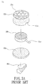
- a prior art earrings type earphone 1c comprises an upper cover 10c, a bottom cover 20c, and a speaker 30c arranged in the inner space between the upper cover 10c and the bottom cover 20c.
- the speaker 30c is connected to a reception wire 31c, which goes out via a through hole 11c of the upper cover 10c.
- the surface of the upper cover 10c has a plurality of small holes 12c.
- An ear clip 40c is disposed on the back of the bottom cover 20c.
- the earphone 1c is fastened to the ear of the user through the ear clip 40c and the collocation of the upper cover 10c and the bottom cover 20c.
- the earphone 1c is used like an earrings worn at the earlobe so that the user can still communicate with others when listening to music.
- the above earrings type earphone is primarily clipped at the earlobe of the user as an earrings. It also belongs to near-ear earphones.
- the produced tone is also of low quality.
- the earphone body is directly plugged into the ear of the user. Because the earphone directly contacts the ear, stress to the ear will cause discomfort after longtime use, and the user has to temporarily take off the earphone, hence being not able to continue enjoying the music. Moreover, because the earphone is plugged into the ear to directly contact the ear, dirt and grease in the ear will accumulate on the earphone after longtime use to cause a problem in sanction. According to a U.S. report, plugging an earphone into the ear for a long time will not only cause discomfort and sharp pain of the user, the bacteria on the earphone will also cause inflammation of the ear, hence having much doubt in sanction. Moreover, if the user uses the earphone improperly, the earphone will harm his body or even endanger his life.
- the prior art earphone is plugged into the ear to achieve a shutting feeling so as to isolate external sound. This shutting feeling will easily make the user hard to be conscious of the external situation. The user will thus act or react hesitantly to cause much doubt in safety.
- the earphone is designed to be a near-ear earphone. Its tone is of low quality, and the low-pitched tone easily scatters and cannot be effectively concentrated. Therefore, a stereo effect of music cannot be effectively accomplished. Moreover, the tone of music cannot be enhanced through a special design of the earphone.
- WO97/11573 describes a portable, wearable personal audio system which includes an acoustic sample chamber and an acoustically transparent ear insert member.
- a tubular member transmits the audio from the sample chamber and module to the ear canal.
- US6186269 describes a compact loudspeaker having a vertically oriented cylindrical housing supporting a relatively high frequency sound driver and a relatively low frequency sound driver.
- US2005/0286717 describes a headset assembly including a moisture-proof and temperature resistant headset module.
- the headset module is sealed against moisture and is constructed from materials that are durable and can withstand constant use, physical abuse, and rapid swings in temperature and other environmental conditions.
- the present invention aims to propose a personal voice-transmitting device to solve the above problems in the prior art.
- An object of the present invention is to provide a personal voice-transmitting device to improve the insufficiency of low-pitched tone of the prior art earphones and concentrate the voice and guide its direction so as to avoid scattering of voice and bad sound effect.
- Another object of the present invention is to provide a personal voice-transmitting device to concentrate the voice and emit the voice toward the ears of the user so that the user can fully enjoy the sound effect. Moreover, the device won't produce much influence to the nearby environment and won't unduly affect others.
- the user needs not to let the earphone directly contact with his ears. Therefore, the drawbacks in the prior art such as poor tone because of using an earphone, a shutting stress and an uncomfortable feeling because of inserting an earphone, an unsafe feeling because of hanging an earphone, a sanitation problem because of contacting an earphone and a safety problem of isolating sound of the outside world can be solved.
- Yet another object of the present invention is to provide a personal voice-transmitting device, in which a voice-transmitting tube extends from a main body, and a first space in the main body and a speaker together generates and retains a resonance tone by a resonance of the first space.
- the resonance tone is transmitting to the ears of the user via the voice-transmitting tube.
- the present invention provides an earphone according to claim 1.
- the present invention provides a personal voice-transmitting device 2, which comprises a multimedia player 20, at least one voice box 21 and at least one voice-transmitting tube 23.
- the multimedia player 20 is flat, and can play MP3 music and listen to AM (Amplitude Modulation) and FM (Frequency Modulation) radio.
- the multimedia player 20 can of designed to be of any shape such as circular arc-shaped, rectangular shape, and so on.
- a control switch 201 is disposed on the multimedia player 20 to control the on/off state of the multimedia player 20.
- another control switch 201 (not shown) can be disposed on the voice-transmitting tube 23 to control the voice-transmitting system (e.g., a speaker 22 electrically connected to this control switch 201) in the voice-transmitting tube 23.
- the voice box 21 can be square or circular arc-shaped.
- Figs. 4 to 6 show a first embodiment of the present invention.
- two voice boxes 21 connect to two sides of the multimedia player 20, respectively.
- Each voice box 21 is movably and pivotally joined with the multimedia player 20.
- Two extension portions 210 extend from one side of each voice box 21.
- Each pivotal portion 203 forms at two sides of the multimedia player 20 respectively.
- the extension portions 210 are pivotally joined with the pivotal portions 203 respectively.
- Each voice box 21 is hollow.
- a speaker 22 can be arranged in each voice box 21 to provide high-pitched tone, middle-pitched tone and low-pitched tone.
- Each voice box 21 is divided to a first space 211 and a second space 212 by the speaker 22.
- a voice reflecting layer 214 e.g., ceramic layer, metal layer or voice-absorbing material
- the speaker 22 is electrically connected to the multimedia player 20.
- two voice blocking controllers 202 can be disposed on the multimedia player 20.
- the two voice blocking controller 202 are electrically connected the two speakers 22 to control the on/off function of sound output of the speakers 22, respectively.
- the voice blocking controllers 202 can be disposed at appropriated positions on the voice boxes 21 to control the on/off function of sound output of the speakers 22, respectively.
- a protruding portion 213 extends outwardly from the other side of each voice box 21.
- the diameter of the protruding portion 213 is the same as that of the speaker 22.
- the voice-transmitting tubes 23 connect to the protruding portions 213 and extend outwardly and bend. The diameter of the voice-transmitting tube 23 gradually decreases when extending outwardly.
- the voice-transmitting tubes 23 movably connect in the protruding portions 213 to allow the voice-transmitting tubes 23 to have the functions of adjusting length and angle.
- the multimedia player 20 is further connected to a voice splitter 204.
- the voice splitter 204 can be disposed in the multimedia player 20.
- the voice splitter 204 is electrically connected to the speakers 22 to control the sound effect of the speakers 22.
- the voice-transmitting tube 23 is hollow.
- An outlet 230 is disposed at the front end of each voice-transmitting tube 23.
- Each outlet 230 is designed to be of arc-shaped.
- Another voice reflecting layer 231 e.g., ceramic layer, metal layer or sound absorbing material is formed on the inner wall of each voice-transmitting tube 23.
- a transmission wire (not shown) is connected between the multimedia player 20 and the voice box 21.
- the transmission wire is used to achieve electric connection between the multimedia player 20 and the speaker 22 so that the multimedia player 20 and the voice box 21 can be separated. It is not necessary to pivotally join the multimedia player 20 and the voice box 21.
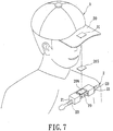
- the multimedia player 20 can be arranged on a hat 3.
- a connecting member 31 e.g., separable connecting member such as magnet or VelcroTM
- Another connecting member 205 is arranged on the multimedia player 20.
- the connecting member 205 of the multimedia player 20 can be joined with the connecting member 31 of the hat 3.
- a shock-voice buffer pad 206 can be disposed on the multimedia player 20.
- the speaker 22 can generate a resonance in the first space 211 of the voice box 21 and a surround effect in the second space 212 by using the voice reflecting layer 214 in the voice box 21.
- the voice-transmitting tube 23 concentrates and guides the voice to the outlet 230 to directly emit the voice toward the user's ears.
- the voice reflecting layer 231 in the voice-transmitting tube 23 can be used to avoid scattering of voice and bad sound effect so that the user can fully enjoy the sound effects.
- the design of the voice-transmitting tube 23 won't much affect the nearby environment.
- the shock-voice buffer pad 206 can be used to avoid the vibration of the speaker 22 that could affect the wearing comfort of the user.
- Figs. 8 to 10 show a personal voice-transmitting device according to a second embodiment of the present invention.
- the personal voice-transmitting device comprises a main body 4, a speaker 5 and a locking structure 6 disposed at the outer side of a first shell 40.
- the main body 4 includes a first shell 40 and a second shell 41 collocated with the first shell 40.
- the first shell 40 and the second shell 41 are assembled together in a locking manner (or the first shell 40 and the second shell 41 can be integrally formed together).
- the first shell has a first space 400 and a voice-transmitting tube 401 extending outwardly from the first shell 40.
- the second shell 41 has a second space 410.
- the speaker 5 is disposed between the first shell 40 and the second shell and near the first space 400.
- the speaker 5 generates and retains a resonance tone by a resonance of the first space 400, and the resonance tone is transmitting to the outlet 402 of the voice-transmitting tube 401 via the voice-transmitting tube 401.
- the user can enjoy excellent sound effects by using the first space 400 and the speaker 5 without affecting his hearing.
- the second shell 41 has a resonance box 411 received in the second space 410.
- the user can also enjoy a resonance tone by the resonance of the speaker 5 and the resonance box 411.
- the locking structure 6 is composed of a silicone member 61 and a magnet 62 disposed on the silicone member 61. Through the elasticity of the silicone member 61 of the locking structure 6, the main body 4 is elastically hung on the user's ear and is fixed on the user's ear by using the magnet 62.
- the magnet 62 can also stimulate acupuncture points on the ear to enhance the user's health.
- the voice-transmitting tube 401 can extend in a specific manner to let its outlet 402 face the user's ear.
- the speaker 5 can thus retain and generate a resonance tone by a resonance of the first space 400, and the resonance tone can be transmitting to the user's ear canal via the outlet 402 of the voice-transmitting tube 401. It is not necessary to plug the main body 4 into the ear to directly contact the ear so as to cause discomfort and a shutting feeling.
- the outlet 402 can be of an arc shape, a square shape or a circular shape to provide diversified selections for the user.
- the locking structure 6 can also be composed of a leather member and a magnet disposed on the leather member. Through the toughness of the leather member, the user can stably adjust the hanging manner and arbitrarily change different styles according to one's liking.
- the personal voice-transmitting device further comprises an earphone wire 7 electrically connected to the speaker 5 and a magnet button 8 disposed on the earphone wire 7.
- the magnet button 8 Through magnetic adhesion of the magnet button 8 (the earphone wire 7 forms a ring-shaped coil by using the adhesion of the magnet button 8), the user can hang the earphone wire 7 on his body (e.g., his neck).
- the main body 4 can be temporarily unloaded on the shoulder without directly falling on the ground.
- the personal voice-transmitting device he can conveniently and quickly wear the main body on his body.
- the earphone wire 7 can be hung on the user's body by using the magnet button 8.
- the magnet button 8 When the earphone wire 7 is carelessly pulled by an external force, the magnet button 8 will also be pulled by the external force to let the earphone wire 7 automatically separate. Therefore, the user won't be pulled by the earphone wire 7 hung on his body to cause any hazard.
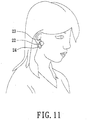
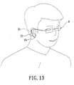
- Figs. 11 to 14 show a personal voice-transmitting device according to a third embodiment of the present invention.
- the connection member 24 is an ear clip or an ear hanger
- the speaker 22 can be fastened at the upper portion (ear pinna) or the lower portion (earlobe) of the user's ear so that the user can conveniently wear the device on his ears.
- the voice-transmitting tube 23 corresponds to the external ear canals of the user's ears.
- the speaker 22 can emit an excellent tone via the voice-transmitting tube 23 without directly contacting the user's ear canals.
- connection member 24 when the connection member 24 is an anti-slip hook or a collar, the user can sleeve the connection member 24 at an appropriate position of a glasses frame 9.
- the voice-transmitting tube 23 corresponds to the external ear canals of the user's ears.
- the speaker 22 can emit an excellent tone via the voice-transmitting tube 23 without directly contacting the ear canals of the user's ears. Therefore, the user needs not to wear the earphone in his ears, hence avoiding uncomfortable feeling.
- the speaker 22 is arranged in the voice box 21 to divide the voice box 21 into the first space 211 and the second space 212.
- the voice reflecting layer 214 is formed on the inner wall of the second space 212 to let the speaker 22 achieve a resonance tone effect and a concentration and surround effect, thereby improving the insufficiency of low-pitched tone of the prior art earphones.
- the voice-transmitting tube 23 can also be used to concentrate the tone and guide its direction so as to avoid scattering of tone and bad tone.
- the speaker 22 can be arranged in the voice-transmitting tube 23 to provide similar effects. Furthermore, voice is concentratedly emitted to surround the user's ears so that the user can fully enjoy the tone without much affecting the nearby environment.
- the voice-transmitting tubes 23 are exposed, there is no influence. Besides, because the voice-transmitting tubes 23 do not directly contact the user's ears, the drawbacks in the prior art such as poor tone because of using an earphone, a shutting stress and an uncomfortable feeling because of inserting an earphone, an unsafe feeling because of hanging an earphone and a sanitation problem because of contacting an earphone can be solved. Moreover, the device can be used with no restriction on occasions and time.
- the speaker 22 can be arranged in the voice box 21 to provide high-pitched tone, middle-pitched tone or low-pitched tone.
- the device can apply to 5.1 or7.1 sound channel earphones.
- these earphones have the problem that surround sound effects are hard to simulate (because the speaker is in the earflap of the earphone), the voice-transmitting tube 23 can be used to guide voice into the earflap of the earphone to simulate the earflap as the living-room space.
- the present invention can be designed to be an open player.
- the device can be joined with a hat 3 to show head-mounted acoustics effect.
- the music output is emitted to the ears with a large area to achieve sound effects as acoustics.
- the user can safely enjoy music when doing leisure activities in an open space.
- the present invention can achieve a personal playback design.
- the device can be joined with a connection member 24 such as an ear clip or an ear hanger, and the voice-transmitting tube 23 extends to the external ear canal of the user to emit voice toward the user's ears.
- the sound volume and tone are like those of prior art earphones, but the first space of the speaker 22 replaces the role of the user's ears (ear cavity) in the prior art earphones for resonance.
- the obtained low-pitched tone is excellent.
- the user can wear the device for a long time. When there is an incoming call, the user can answer the call by using a Bluetooth module and a microphone without taking off the device. That is, the device can become part of the user's clothing.
Landscapes
- Physics & Mathematics (AREA)
- Engineering & Computer Science (AREA)
- Acoustics & Sound (AREA)
- Signal Processing (AREA)
- Details Of Audible-Bandwidth Transducers (AREA)
- Headphones And Earphones (AREA)
Claims (10)
- Ohrhörer (2) mit:einem Hauptkörper, der eine erste Schale (40) und eine zweite Schale (41) beinhaltet, die mit der ersten Schale (40) zusammengefügt ist, wobei die erste Schale (40) einen ersten Raum (400) und die zweite Schale (4) einen zweiten Raum (410) aufweist;einer Schallübertragungsröhre (401), die sich von der ersten Schale (40) nach außen erstreckt, wobei die Schallübertragungsröhre einen Auslass (402) aufweist;einen Lautsprecher (5), der zwischen dem ersten Raum (400) und dem zweiten Raum (410) angeordnet ist, undein Verbindungselement (24), das so angeordnet ist, dass der Auslass der Schallübertragungsröhre angeordnet sein kann, dass er einem Ohr eines Benutzers zugewandt ist,wobei der Lautsprecher (5) einen Resonanzton in dem ersten Raum (400) bildet und der Resonanzton zu dem Auslass (402) und dann über die Schallübertragungsröhre (401) zu dem Ohr eines Benutzers übertragen wird,dadurch gekennzeichnet, dassder Ohrhörer (2) mit dem Verbindungselement (24) derart verbunden ist, dass, in Gebrauch, der Auslass der Schallübertragungsröhre dem Ohr eines Benutzers zugewandt ist, so dass die Übertragungsröhre das Ohr des Benutzers nicht direkt berührt und es somit nicht notwendig ist, die Schallübertragungsröhre (401) in das Ohr eines Benutzers zu stecken.
- Ohrhörer nach Anspruch 1, ferner gekennzeichnet durch ein Ohrhörerkabel, das elektrisch mit dem Lautsprecher und einem Magnetknopf (8) verbunden ist, der auf dem Ohrhörerkabel angeordnet ist.
- Ohrhörer (2) nach Anspruch 1 oder 2, dadurch gekennzeichnet, dass das Verbindungselement (24) aus
einem ersten Befestigungselement, das an einer Seite an dem Hauptkörper befestigt ist, und einem ersten Magneten, der an der anderen Seite des ersten Befestigungselements angebracht ist;
einem elastischen Band, das an einem Ende mit dem ersten Befestigungselement verbunden ist;
und einem zweiten Befestigungselement, das an einer Seite an dem Band befestigt ist, und einem zweiten Magneten besteht, der an der anderen Seite des zweiten Befestigungselements angebracht ist; und
das Verbindungselement (24) an einem Ohr eines Benutzers durch den ersten und den zweiten Magnet fixiert ist, die sich auf gegenüberliegenden Seiten eines Ohrläppchens befinden. - Ohrhörer (2) nach einem der vorhergehenden Ansprüche, dadurch gekennzeichnet, dass das Verbindungselement (24) ein Ohrclip ist.
- Ohrhörer (2) nach einem der vorhergehenden Ansprüche, dadurch gekennzeichnet, dass der Auslass bogenförmig ist.
- Ohrhörer (2) nach einem der vorhergehenden Ansprüche, dadurch gekennzeichnet, dass sich die Schallübertragungsröhre zu dem äußeren Gehörgang der Ohren des Benutzers erstreckt, es jedoch nicht notwendig ist, die Schallübertragungsröhre (401) in das Ohr des Benutzers zu stecken.
- Ohrhörer (2) nach Anspruch 5, dadurch gekennzeichnet, dass der Ohrhörer (2) so angeordnet ist, dass der Hauptkörper an der Ohrmuschel des Benutzers befestigt ist.
- Ohrhörer (2) nach Anspruch 4, dadurch gekennzeichnet, dass der Ohrhörer (2) so angeordnet ist, dass der Hauptkörper am Ohrläppchen des Benutzers befestigt ist.
- Ohrhörer (2) nach einem der vorhergehenden Ansprüche, dadurch gekennzeichnet, dass sich die Schallübertragungsröhre von der ersten Schale nach außen erstreckt.
- Ohrhörerset mit einem ersten und einem zweiten Ohrhörer (2) nach einem der vorhergehenden Ansprüche; und
mit einem ersten und zweiten Ohrhörerkabel, die jeweils zwischen einer Tonquelle und einem Lautsprecher des ersten und des zweiten Ohrhörers (2) angeschlossen sind.
Applications Claiming Priority (1)
| Application Number | Priority Date | Filing Date | Title |
|---|---|---|---|
| CN 200610066726 CN101052238B (zh) | 2006-04-05 | 2006-04-05 | 随身式导音装置 |
Publications (3)
| Publication Number | Publication Date |
|---|---|
| EP1843627A1 EP1843627A1 (de) | 2007-10-10 |
| EP1843627B1 true EP1843627B1 (de) | 2018-07-25 |
| EP1843627B8 EP1843627B8 (de) | 2018-09-05 |
Family
ID=37964942
Family Applications (1)
| Application Number | Title | Priority Date | Filing Date |
|---|---|---|---|
| EP06126546.8A Active EP1843627B8 (de) | 2006-04-05 | 2006-12-19 | Persönliche Sprachübertragungsvorrichtung |
Country Status (2)
| Country | Link |
|---|---|
| EP (1) | EP1843627B8 (de) |
| CN (1) | CN101052238B (de) |
Families Citing this family (16)
| Publication number | Priority date | Publication date | Assignee | Title |
|---|---|---|---|---|
| US8111854B2 (en) | 2006-11-29 | 2012-02-07 | Yan-Ru Peng | Methods and apparatus for sound production |
| CN102780939B (zh) * | 2011-05-09 | 2015-06-24 | 淇誉电子科技股份有限公司 | 挂戴式多指向性音响装置 |
| ITGE20120066A1 (it) * | 2012-07-03 | 2014-01-04 | Pisani Alberto Costa | Dispositivo interfono |
| US10063958B2 (en) | 2014-11-07 | 2018-08-28 | Microsoft Technology Licensing, Llc | Earpiece attachment devices |
| US20160134958A1 (en) * | 2014-11-07 | 2016-05-12 | Microsoft Technology Licensing, Llc | Sound transmission systems and devices having earpieces |
| US9723396B2 (en) | 2015-06-29 | 2017-08-01 | Apple Inc. | Earphone assemblies with magnets for anchoring to a user |
| JP6284967B2 (ja) * | 2016-03-04 | 2018-02-28 | 株式会社オーディオテクニカ | イヤホン |
| CN105831862A (zh) * | 2016-05-07 | 2016-08-10 | 常州大果智能科技有限公司 | 头盔 |
| CN107547992A (zh) * | 2016-06-29 | 2018-01-05 | 宏碁股份有限公司 | 低频延伸的扬声器及应用该扬声器的电子装置 |
| CN106170118A (zh) * | 2016-09-23 | 2016-11-30 | 深圳前海零距物联网科技有限公司 | 新型音频输出装置 |
| WO2019148393A1 (zh) * | 2018-01-31 | 2019-08-08 | 高驰运动科技(深圳)有限公司 | 一种带有耳机的头盔 |
| CN108882137A (zh) * | 2018-07-09 | 2018-11-23 | 上海电机学院 | 腰挂式扩音器 |
| TWI735799B (zh) * | 2018-08-28 | 2021-08-11 | 宏碁股份有限公司 | 頭戴式顯示設備以及揚聲裝置 |
| US10602256B1 (en) * | 2018-10-15 | 2020-03-24 | Coros Wearables Inc. | Earphone and a method of operating the earphone |
| CN110507042B (zh) * | 2019-09-06 | 2021-11-26 | 歌尔股份有限公司 | 一种腕戴设备 |
| CN111556400A (zh) * | 2020-06-12 | 2020-08-18 | 陈晨 | 一种耳机 |
Citations (6)
| Publication number | Priority date | Publication date | Assignee | Title |
|---|---|---|---|---|
| US4864610A (en) * | 1987-02-27 | 1989-09-05 | Acs Communications, Inc. | Earpiece for a telephone headset |
| DE29720969U1 (de) * | 1997-11-04 | 1998-02-12 | Lee, Chun-Sheng, Taipeh/T'ai-pei | Ausführungsform einer Hörerklammer |
| WO1999050706A1 (en) * | 1998-03-31 | 1999-10-07 | Egidio Renna | Spectacles framework with earphone bars |
| WO2000005924A1 (en) * | 1998-07-22 | 2000-02-03 | Resound Corporation | Two-way communication earpiece |
| KR20050013725A (ko) * | 2003-07-29 | 2005-02-05 | 크레신 주식회사 | 귀걸이형 헤드폰 |
| US20060008106A1 (en) * | 2004-07-06 | 2006-01-12 | Harper Patrick S | System and method for securing headphone transducers |
Family Cites Families (5)
| Publication number | Priority date | Publication date | Assignee | Title |
|---|---|---|---|---|
| US5694475A (en) | 1995-09-19 | 1997-12-02 | Interval Research Corporation | Acoustically transparent earphones |
| US6356644B1 (en) * | 1998-02-20 | 2002-03-12 | Sony Corporation | Earphone (surround sound) speaker |
| US6186269B1 (en) | 1998-12-11 | 2001-02-13 | Edward Vollmer | Mini surround sound loudspeaker |
| US20050110644A1 (en) * | 2003-11-20 | 2005-05-26 | Jeffrey Abramson | Enuresis device with magnetic fastener |
| US7391863B2 (en) | 2004-06-23 | 2008-06-24 | Vocollect, Inc. | Method and system for an interchangeable headset module resistant to moisture infiltration |
-
2006
- 2006-04-05 CN CN 200610066726 patent/CN101052238B/zh not_active Expired - Lifetime
- 2006-12-19 EP EP06126546.8A patent/EP1843627B8/de active Active
Patent Citations (6)
| Publication number | Priority date | Publication date | Assignee | Title |
|---|---|---|---|---|
| US4864610A (en) * | 1987-02-27 | 1989-09-05 | Acs Communications, Inc. | Earpiece for a telephone headset |
| DE29720969U1 (de) * | 1997-11-04 | 1998-02-12 | Lee, Chun-Sheng, Taipeh/T'ai-pei | Ausführungsform einer Hörerklammer |
| WO1999050706A1 (en) * | 1998-03-31 | 1999-10-07 | Egidio Renna | Spectacles framework with earphone bars |
| WO2000005924A1 (en) * | 1998-07-22 | 2000-02-03 | Resound Corporation | Two-way communication earpiece |
| KR20050013725A (ko) * | 2003-07-29 | 2005-02-05 | 크레신 주식회사 | 귀걸이형 헤드폰 |
| US20060008106A1 (en) * | 2004-07-06 | 2006-01-12 | Harper Patrick S | System and method for securing headphone transducers |
Also Published As
| Publication number | Publication date |
|---|---|
| CN101052238A (zh) | 2007-10-10 |
| EP1843627A1 (de) | 2007-10-10 |
| EP1843627B8 (de) | 2018-09-05 |
| CN101052238B (zh) | 2013-05-01 |
Similar Documents
| Publication | Publication Date | Title |
|---|---|---|
| US11503394B2 (en) | TWS bone conduction earphone | |
| EP1843627B1 (de) | Persönliche Sprachübertragungsvorrichtung | |
| CN107438217B (zh) | 无线音响设备 | |
| JP5473640B2 (ja) | スピーカー装置 | |
| CN1316853C (zh) | 耳机 | |
| TWI644573B (zh) | Headphone type audio device | |
| CN100512335C (zh) | 音频耳机 | |
| CN108702560B (zh) | 声音输出装置 | |
| JP2011521560A (ja) | 耳掛けとイヤホン本体のヘッドセット | |
| TW200845796A (en) | Headset with exhangeable speaker | |
| JP2002058085A (ja) | 身体セット型スピーカ装置 | |
| US20090226024A1 (en) | Speaker enclosure and headphone | |
| TW201306607A (zh) | 整合有麥克風的耳機 | |
| KR101762671B1 (ko) | 이어셋 | |
| US20070160245A1 (en) | Personal voice-transmitted device | |
| KR20060043937A (ko) | 이어폰 | |
| KR101694706B1 (ko) | 이어셋 | |
| US20060147079A1 (en) | Earphone | |
| KR20110010033A (ko) | 골전도(骨傳導) 이어폰 | |
| KR100825335B1 (ko) | 음향기기용 이어폰 | |
| KR101427120B1 (ko) | 트라거스에 착용할 수 있는 이어폰 | |
| CN223859211U (zh) | 无线耳机 | |
| CN117098027B (zh) | 一种骨传导耳机及耳机套装 | |
| KR200441215Y1 (ko) | 착용식 도음 장치 | |
| CN223110153U (zh) | 一种耳机 |
Legal Events
| Date | Code | Title | Description |
|---|---|---|---|
| PUAI | Public reference made under article 153(3) epc to a published international application that has entered the european phase |
Free format text: ORIGINAL CODE: 0009012 |
|
| AK | Designated contracting states |
Kind code of ref document: A1 Designated state(s): AT BE BG CH CY CZ DE DK EE ES FI FR GB GR HU IE IS IT LI LT LU LV MC NL PL PT RO SE SI SK TR |
|
| AX | Request for extension of the european patent |
Extension state: AL BA HR MK YU |
|
| 17P | Request for examination filed |
Effective date: 20080219 |
|
| 17Q | First examination report despatched |
Effective date: 20080326 |
|
| AKX | Designation fees paid |
Designated state(s): AT BE BG CH CY CZ DE DK EE ES FI FR GB GR HU IE IS IT LI LT LU LV MC NL PL PT RO SE SI SK TR |
|
| GRAP | Despatch of communication of intention to grant a patent |
Free format text: ORIGINAL CODE: EPIDOSNIGR1 |
|
| STAA | Information on the status of an ep patent application or granted ep patent |
Free format text: STATUS: GRANT OF PATENT IS INTENDED |
|
| INTG | Intention to grant announced |
Effective date: 20180202 |
|
| GRAS | Grant fee paid |
Free format text: ORIGINAL CODE: EPIDOSNIGR3 |
|
| GRAA | (expected) grant |
Free format text: ORIGINAL CODE: 0009210 |
|
| STAA | Information on the status of an ep patent application or granted ep patent |
Free format text: STATUS: THE PATENT HAS BEEN GRANTED |
|
| GRAT | Correction requested after decision to grant or after decision to maintain patent in amended form |
Free format text: ORIGINAL CODE: EPIDOSNCDEC |
|
| AK | Designated contracting states |
Kind code of ref document: B1 Designated state(s): AT BE BG CH CY CZ DE DK EE ES FI FR GB GR HU IE IS IT LI LT LU LV MC NL PL PT RO SE SI SK TR |
|
| REG | Reference to a national code |
Ref country code: GB Ref legal event code: FG4D |
|
| REG | Reference to a national code |
Ref country code: CH Ref legal event code: EP |
|
| REG | Reference to a national code |
Ref country code: CH Ref legal event code: PK Free format text: BERICHTIGUNG B8 Ref country code: AT Ref legal event code: REF Ref document number: 1023062 Country of ref document: AT Kind code of ref document: T Effective date: 20180815 |
|
| REG | Reference to a national code |
Ref country code: DE Ref legal event code: R096 Ref document number: 602006055887 Country of ref document: DE |
|
| REG | Reference to a national code |
Ref country code: IE Ref legal event code: FG4D |
|
| REG | Reference to a national code |
Ref country code: NL Ref legal event code: MP Effective date: 20180725 |
|
| REG | Reference to a national code |
Ref country code: LT Ref legal event code: MG4D |
|
| PG25 | Lapsed in a contracting state [announced via postgrant information from national office to epo] |
Ref country code: NL Free format text: LAPSE BECAUSE OF FAILURE TO SUBMIT A TRANSLATION OF THE DESCRIPTION OR TO PAY THE FEE WITHIN THE PRESCRIBED TIME-LIMIT Effective date: 20180725 |
|
| REG | Reference to a national code |
Ref country code: AT Ref legal event code: MK05 Ref document number: 1023062 Country of ref document: AT Kind code of ref document: T Effective date: 20180725 |
|
| PG25 | Lapsed in a contracting state [announced via postgrant information from national office to epo] |
Ref country code: FI Free format text: LAPSE BECAUSE OF FAILURE TO SUBMIT A TRANSLATION OF THE DESCRIPTION OR TO PAY THE FEE WITHIN THE PRESCRIBED TIME-LIMIT Effective date: 20180725 Ref country code: AT Free format text: LAPSE BECAUSE OF FAILURE TO SUBMIT A TRANSLATION OF THE DESCRIPTION OR TO PAY THE FEE WITHIN THE PRESCRIBED TIME-LIMIT Effective date: 20180725 Ref country code: SE Free format text: LAPSE BECAUSE OF FAILURE TO SUBMIT A TRANSLATION OF THE DESCRIPTION OR TO PAY THE FEE WITHIN THE PRESCRIBED TIME-LIMIT Effective date: 20180725 Ref country code: IS Free format text: LAPSE BECAUSE OF FAILURE TO SUBMIT A TRANSLATION OF THE DESCRIPTION OR TO PAY THE FEE WITHIN THE PRESCRIBED TIME-LIMIT Effective date: 20181125 Ref country code: PL Free format text: LAPSE BECAUSE OF FAILURE TO SUBMIT A TRANSLATION OF THE DESCRIPTION OR TO PAY THE FEE WITHIN THE PRESCRIBED TIME-LIMIT Effective date: 20180725 Ref country code: BG Free format text: LAPSE BECAUSE OF FAILURE TO SUBMIT A TRANSLATION OF THE DESCRIPTION OR TO PAY THE FEE WITHIN THE PRESCRIBED TIME-LIMIT Effective date: 20181025 Ref country code: GR Free format text: LAPSE BECAUSE OF FAILURE TO SUBMIT A TRANSLATION OF THE DESCRIPTION OR TO PAY THE FEE WITHIN THE PRESCRIBED TIME-LIMIT Effective date: 20181026 Ref country code: LT Free format text: LAPSE BECAUSE OF FAILURE TO SUBMIT A TRANSLATION OF THE DESCRIPTION OR TO PAY THE FEE WITHIN THE PRESCRIBED TIME-LIMIT Effective date: 20180725 |
|
| PG25 | Lapsed in a contracting state [announced via postgrant information from national office to epo] |
Ref country code: ES Free format text: LAPSE BECAUSE OF FAILURE TO SUBMIT A TRANSLATION OF THE DESCRIPTION OR TO PAY THE FEE WITHIN THE PRESCRIBED TIME-LIMIT Effective date: 20180725 Ref country code: LV Free format text: LAPSE BECAUSE OF FAILURE TO SUBMIT A TRANSLATION OF THE DESCRIPTION OR TO PAY THE FEE WITHIN THE PRESCRIBED TIME-LIMIT Effective date: 20180725 |
|
| REG | Reference to a national code |
Ref country code: DE Ref legal event code: R097 Ref document number: 602006055887 Country of ref document: DE |
|
| PG25 | Lapsed in a contracting state [announced via postgrant information from national office to epo] |
Ref country code: EE Free format text: LAPSE BECAUSE OF FAILURE TO SUBMIT A TRANSLATION OF THE DESCRIPTION OR TO PAY THE FEE WITHIN THE PRESCRIBED TIME-LIMIT Effective date: 20180725 Ref country code: CZ Free format text: LAPSE BECAUSE OF FAILURE TO SUBMIT A TRANSLATION OF THE DESCRIPTION OR TO PAY THE FEE WITHIN THE PRESCRIBED TIME-LIMIT Effective date: 20180725 Ref country code: RO Free format text: LAPSE BECAUSE OF FAILURE TO SUBMIT A TRANSLATION OF THE DESCRIPTION OR TO PAY THE FEE WITHIN THE PRESCRIBED TIME-LIMIT Effective date: 20180725 |
|
| PG25 | Lapsed in a contracting state [announced via postgrant information from national office to epo] |
Ref country code: DK Free format text: LAPSE BECAUSE OF FAILURE TO SUBMIT A TRANSLATION OF THE DESCRIPTION OR TO PAY THE FEE WITHIN THE PRESCRIBED TIME-LIMIT Effective date: 20180725 Ref country code: SK Free format text: LAPSE BECAUSE OF FAILURE TO SUBMIT A TRANSLATION OF THE DESCRIPTION OR TO PAY THE FEE WITHIN THE PRESCRIBED TIME-LIMIT Effective date: 20180725 |
|
| PLBE | No opposition filed within time limit |
Free format text: ORIGINAL CODE: 0009261 |
|
| STAA | Information on the status of an ep patent application or granted ep patent |
Free format text: STATUS: NO OPPOSITION FILED WITHIN TIME LIMIT |
|
| 26N | No opposition filed |
Effective date: 20190426 |
|
| REG | Reference to a national code |
Ref country code: CH Ref legal event code: PL |
|
| PG25 | Lapsed in a contracting state [announced via postgrant information from national office to epo] |
Ref country code: SI Free format text: LAPSE BECAUSE OF FAILURE TO SUBMIT A TRANSLATION OF THE DESCRIPTION OR TO PAY THE FEE WITHIN THE PRESCRIBED TIME-LIMIT Effective date: 20180725 Ref country code: MC Free format text: LAPSE BECAUSE OF FAILURE TO SUBMIT A TRANSLATION OF THE DESCRIPTION OR TO PAY THE FEE WITHIN THE PRESCRIBED TIME-LIMIT Effective date: 20180725 Ref country code: LU Free format text: LAPSE BECAUSE OF NON-PAYMENT OF DUE FEES Effective date: 20181219 |
|
| REG | Reference to a national code |
Ref country code: IE Ref legal event code: MM4A |
|
| REG | Reference to a national code |
Ref country code: BE Ref legal event code: MM Effective date: 20181231 |
|
| PG25 | Lapsed in a contracting state [announced via postgrant information from national office to epo] |
Ref country code: IE Free format text: LAPSE BECAUSE OF NON-PAYMENT OF DUE FEES Effective date: 20181219 |
|
| PG25 | Lapsed in a contracting state [announced via postgrant information from national office to epo] |
Ref country code: BE Free format text: LAPSE BECAUSE OF NON-PAYMENT OF DUE FEES Effective date: 20181231 |
|
| PG25 | Lapsed in a contracting state [announced via postgrant information from national office to epo] |
Ref country code: CH Free format text: LAPSE BECAUSE OF NON-PAYMENT OF DUE FEES Effective date: 20181231 Ref country code: LI Free format text: LAPSE BECAUSE OF NON-PAYMENT OF DUE FEES Effective date: 20181231 |
|
| PG25 | Lapsed in a contracting state [announced via postgrant information from national office to epo] |
Ref country code: TR Free format text: LAPSE BECAUSE OF FAILURE TO SUBMIT A TRANSLATION OF THE DESCRIPTION OR TO PAY THE FEE WITHIN THE PRESCRIBED TIME-LIMIT Effective date: 20180725 |
|
| PG25 | Lapsed in a contracting state [announced via postgrant information from national office to epo] |
Ref country code: PT Free format text: LAPSE BECAUSE OF FAILURE TO SUBMIT A TRANSLATION OF THE DESCRIPTION OR TO PAY THE FEE WITHIN THE PRESCRIBED TIME-LIMIT Effective date: 20180725 |
|
| PG25 | Lapsed in a contracting state [announced via postgrant information from national office to epo] |
Ref country code: HU Free format text: LAPSE BECAUSE OF FAILURE TO SUBMIT A TRANSLATION OF THE DESCRIPTION OR TO PAY THE FEE WITHIN THE PRESCRIBED TIME-LIMIT; INVALID AB INITIO Effective date: 20061219 Ref country code: CY Free format text: LAPSE BECAUSE OF FAILURE TO SUBMIT A TRANSLATION OF THE DESCRIPTION OR TO PAY THE FEE WITHIN THE PRESCRIBED TIME-LIMIT Effective date: 20180725 |
|
| PGFP | Annual fee paid to national office [announced via postgrant information from national office to epo] |
Ref country code: GB Payment date: 20241230 Year of fee payment: 19 |
|
| PGFP | Annual fee paid to national office [announced via postgrant information from national office to epo] |
Ref country code: FR Payment date: 20241231 Year of fee payment: 19 |
|
| PGFP | Annual fee paid to national office [announced via postgrant information from national office to epo] |
Ref country code: DE Payment date: 20250121 Year of fee payment: 19 |
|
| PGFP | Annual fee paid to national office [announced via postgrant information from national office to epo] |
Ref country code: IT Payment date: 20241231 Year of fee payment: 19 |