EP1843629A1 - Lautsprecherdämpfer, herstellungsverfahren dafür sowie lautsprecher und elektronische vorrichtung damit - Google Patents
Lautsprecherdämpfer, herstellungsverfahren dafür sowie lautsprecher und elektronische vorrichtung damit Download PDFInfo
- Publication number
- EP1843629A1 EP1843629A1 EP06712152A EP06712152A EP1843629A1 EP 1843629 A1 EP1843629 A1 EP 1843629A1 EP 06712152 A EP06712152 A EP 06712152A EP 06712152 A EP06712152 A EP 06712152A EP 1843629 A1 EP1843629 A1 EP 1843629A1
- Authority
- EP
- European Patent Office
- Prior art keywords
- loudspeaker
- damper
- resin
- base material
- manufacturing
- Prior art date
- Legal status (The legal status is an assumption and is not a legal conclusion. Google has not performed a legal analysis and makes no representation as to the accuracy of the status listed.)
- Withdrawn
Links
Images


Classifications
-
- H—ELECTRICITY
- H04—ELECTRIC COMMUNICATION TECHNIQUE
- H04R—LOUDSPEAKERS, MICROPHONES, GRAMOPHONE PICK-UPS OR LIKE ACOUSTIC ELECTROMECHANICAL TRANSDUCERS; ELECTRIC HEARING AIDS; PUBLIC ADDRESS SYSTEMS
- H04R9/00—Transducers of moving-coil, moving-strip, or moving-wire type
- H04R9/02—Details
- H04R9/04—Construction, mounting, or centering of coil
- H04R9/041—Centering
- H04R9/043—Inner suspension or damper, e.g. spider
-
- H—ELECTRICITY
- H04—ELECTRIC COMMUNICATION TECHNIQUE
- H04R—LOUDSPEAKERS, MICROPHONES, GRAMOPHONE PICK-UPS OR LIKE ACOUSTIC ELECTROMECHANICAL TRANSDUCERS; ELECTRIC HEARING AIDS; PUBLIC ADDRESS SYSTEMS
- H04R7/00—Diaphragms for electromechanical transducers; Cones
- H04R7/16—Mounting or tensioning of diaphragms or cones
-
- H—ELECTRICITY
- H04—ELECTRIC COMMUNICATION TECHNIQUE
- H04R—LOUDSPEAKERS, MICROPHONES, GRAMOPHONE PICK-UPS OR LIKE ACOUSTIC ELECTROMECHANICAL TRANSDUCERS; ELECTRIC HEARING AIDS; PUBLIC ADDRESS SYSTEMS
- H04R2307/00—Details of diaphragms or cones for electromechanical transducers, their suspension or their manufacture covered by H04R7/00 or H04R31/003, not provided for in any of its subgroups
- H04R2307/201—Damping aspects of the outer suspension of loudspeaker diaphragms by addition of additional damping means
-
- H—ELECTRICITY
- H04—ELECTRIC COMMUNICATION TECHNIQUE
- H04R—LOUDSPEAKERS, MICROPHONES, GRAMOPHONE PICK-UPS OR LIKE ACOUSTIC ELECTROMECHANICAL TRANSDUCERS; ELECTRIC HEARING AIDS; PUBLIC ADDRESS SYSTEMS
- H04R2499/00—Aspects covered by H04R or H04S not otherwise provided for in their subgroups
- H04R2499/10—General applications
- H04R2499/13—Acoustic transducers and sound field adaptation in vehicles
Definitions
- the present invention relates to a loudspeaker damper used in various acoustic equipment, a manufacturing method thereof, and a loudspeaker, electronic equipment and a device using the loudspeaker damper.
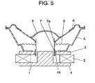
- Fig. 5 is a sectional view showing a configuration of a loudspeaker
- Figs. 6A and 6B are a plan view and a sectional view showing a configuration of a damper used in the loudspeaker. With reference to Figs. 5, 6A and 6B, this loudspeaker is described.
- Magnetic circuit 4 including annular magnetic gap 4a is configured by bottom plate 1 having a convex-shaped cross section, ring magnet 2 provided on bottom plate 1, and ring upper plate 3 provided on magnet 2. Such a configuration is referred to as an outer magnet type.
- Frame 5 is coupled to upper plate 3.
- the outer peripheral portion of diaphragm 6 is coupled to frame 5.
- Voice coil 7 is movably disposed in magnetic gap 4a.
- bobbin 7a on which a coil of voice coil 7 is wound extends to the side of diaphragm 6 and coupled to the inner peripheral portion of diaphragm 6.
- the inner peripheral portion of damper 8 is coupled to bobbin 7a and the outer peripheral portion of damper 8 is coupled to frame 5.
- dust cap 9 On the central part of the upper surface of diaphragm 6, dust cap 9 for preventing entering of dust is provided.
- damper 8 is configured in a concentric circular corrugation form spreading on a surface in order to elastically support voice coil 7 via diaphragm 6 and bobbin 7a. Damper 8 is required to have basic performances of being excellent in retaining stability of voice coil 7 and allowing amplitude motion faithfully responding to stress generated in voice coil 7.
- Damper 8 is manufactured by a manufacturing process shown in Fig. 7. That is to say, a damper base material is introduced, then impregnated with resin in step 701, and dried in step 702. This resin-impregnated damper base material is hot-pressed by using a die so as to form a corrugation shape in step 703. Thereafter, in a trimming process in step 704, an inner diameter and an outer diameter are punched out by using a die.
- a loudspeaker damper a) being less deteriorated in the basic performance; b) being excellent in water resistance, humidity resistance and heat resistance; c) being excellent in shape-keeping property and less deteriorated in a loudspeaker property after long time of use; and d) in manufacturing process, providing a manufacturing method in which impregnation and molding steps are safe without adversely affecting the working environment and harmful gas is not generated.
- the loudspeaker damper proposed in Japanese Patent Unexamined Publication No. H8-340596 includes a cloth composed of fully aromatic polyamide yarns, as a matrix component.
- the fully aromatic polyamide yarn is a mixed yarn mixed with thermoplastic aromatic polyester fibers having a thermal fusion temperature that is lower than a thermal decomposition temperature by 1.00°C or more.
- fully aromatic polyamide fibers are fixed to each other by fusion of the thermoplastic aromatic polyester fibers.
- fibers constituting the yarn and fiber surfaces are fixed to each other by a vehicle containing polyester resin.
- the mixed yarns are fixed to each other at their intersection points by fusion of thermoplastic aromatic polyester fibers and with a vehicle containing polyester resin.
- Japanese Patent Application 2004-196533 a step of subjecting a base material to surface reforming treatment (corona discharge treatment) before a step of impregnating a base material with resin.
- the proposition in Japanese Patent Application 2004-196533 makes it possible to improve the wettability of a base material and to improve the conformability between the base material and impregnated resin.
- the base material can be impregnated with resin sufficiently, and the binding strength between the base material and the resin can be reinforced.
- a damper prevents the oscillation and a resin layer provided on the surface of the damper base material is cracked due to partial interface peeling. Thus, the property is deteriorated.
- a loudspeaker damper of the present invention includes a material and thermosetting resin including 2 to 20 wt% of flexibility imparting agent, in which the material is impregnated with the thermosetting resin.
- the loudspeaker damper of the first exemplary embodiment is obtained by impregnating a material such as fabric, heat-resistant nylon and polyester with thermosetting resin such as phenolic resin and melamine resin, followed by heat curing the resin impregnated material.
- thermosetting resin such as phenolic resin and melamine resin includes 2 to 20% of flexibility imparting agent.
- flexibility imparting agent used in the present invention includes the following well-known flexibility imparting agents:
- liquid rubber is preferable from the viewpoint of compatibility with respect to phenolic resin.
- liquid acrylonitrile-butadiene rubber (NBR) is most preferable because it is effective in modifying phenolic resin.
- the addition amount of the flexibility imparting agent is in the range from 2 to 20 wt% with respect to the amount of thermosetting resin itself, such as phenolic resin and melamine resin.
- the amount of less than 2 wt% is not preferable because the effect cannot be sufficiently exhibited.
- the amount of more than 20 wt% is not preferable because the rigidity of thermosetting resin is lost.
- the most effective and preferable range is in the range from 5 to 10 wt%.
- NBR emulsion is selected as a flexibility imparting agent.
- Nipol registered trademark
- SX1503 is used as this NBR emulsion.
- the glass-transition temperature of NBR is -20°C.
- a damper is produced as follows. Firstly, a material of polyester is used as a damper base material. The material is impregnated with phenolic resin to which the above-mentioned flexibility imparting agent has been added in the amount of 10 wt% in a solid content basis. Then, the resin-impregnated material is heat-cured. The change rate of flexibility after the application of flexure is repeated 1000 times with an amplitude of 5 mm at room temperature is defined as durability of the produced damper. This change rate of flexibility is shown in Table 1 together with the change rate of a conventional product as a comparative example. Table 1 Change rate of flexibility (%) Conventional example 20 Example 1 15 Example 2 12 Second exemplary embodiment 7
- a damper in accordance with this exemplary embodiment has flexibility by the configuration in which a flexibility imparting agent is added to a thermosetting resin layer formed on the surface of the damper base material. Therefore, even if the damper oscillates with a large amplitude, it is possible to prevent a resin layer provided on the surface of the damper base material from being cracked due to partial interface peeling. Thus, the damper can follow a large amplitude sufficiently.
- Example 2 As Example 2, 0.001 mol/100g of hydroxyl group is added to the flexibility imparting agent used in Example 1 and this flexibility imparting agent is added to phenolic resin.
- the phenolic resin is impregnated into a base material, and this resin-impregnated base material is used so as to produce a damper.
- the measurement result of the change rate of flexibility of the thus produced damper is also shown in Table 1.
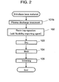
- Fig. 1 is a manufacturing process chart showing a manufacturing method of a loudspeaker damper in accordance with this exemplary embodiment.
- a base material is introduced, in step 101a, the introduced base material is subjected to corona discharge treatment as a surface treatment process.
- resin impregnation process is carried out.
- the base materials is impregnated with the thermosetting resin including the flexibility imparting material described in the first exemplary embodiment.
- the material is dried.
- step 104 the material is hot-pressed by using a die, so that a corrugation shape is formed.
- an inner diameter and an outer diameter are punched out by using a die.
- step 101a With this corona discharge treatment in step 101a, the wettability of the base material is improved so as to increase the coating property and the conformability between the base material and the impregnated resin is improved. Thus, the binding strength between the base material and the impregnated resin can be enhanced.
- this surface reforming treatment process by corona discharge treatment can be carried out by irradiating a base material with corona discharge in the atmosphere, a large-scale facility is not needed. Furthermore, even a wide and long base material can be subjected to surface reforming treatment in an online state consecutively and with a simple method. Thus, the treatment can be carried out at a low cost. Furthermore, in the facility of corona discharge, by using a wire electrode as a discharging electrode, discharge energy can be concentrated. Thus, treatment effect can be obtained uniformly even on an irregular surface of a base material such as a woven fabric.
- a chemical fiber material is used for a damper base material, although moisture absorption is smaller as compared with a cotton yarn material, the conformability with respect to resin to be impregnated is often poor.
- polyester is widely used as a substitute for a cotton yarn material, and polyester is cheap and highly versatile chemical fiber material next to a cotton yarn material. Even when a chemical fiber material is used, by carrying out the surface reforming treatment, the wettability of a base material is improved, so that the conformability with respect to impregnated resin is improved. Thus, binding strength between the base material and the impregnated resin can be enhanced.
- the chemical fiber material is not necessarily limited to polyester, and any materials, for example, rayon, aramid, or the like, can be selected in accordance with the required performances. As to texture, many options including woven fabric and knitted fabric are possible.
- the material before the step of impregnating the damper base material with phenolic resin including a flexibility imparting agent, the material is subjected to surface reforming treatment by corona discharge treatment.
- This manufacturing method can improve the wettability of the base material so as to increase the coating property, and improve the conformability between the base material and the impregnated resin.
- binding strength between the base material and the impregnated resin can be enhanced.
- the change rate of flexibility can be considerably improved.
- Example 2 As the durability of the damper in a loudspeaker using the damper obtained in Example 1, Example 2, and the second exemplary embodiment, the change rate of the minimum resonance frequency (f 0 ) of a loudspeaker using this loudspeaker damper is measured after the loudspeaker is continuously operated for 96 hours in high temperature and high humidity environment. The results are shown in Table 2 together with that of a conventional product. Table 2 Loudspeaker fo change rate (%) Conventional example 30 Example 1 23 Example 2 18 Second exemplary embodiment 13
- the loudspeaker damper in accordance with this exemplary embodiment has flexibility since a resin layer provided on the surface of the damper base material is a material containing a flexibility imparting agent. Therefore, even if a large input is applied to the loudspeaker, so that the damper oscillates with a large amplitude, the loudspeaker damper can follow such a large amplitude. Thus, it is possible to prevent the resin layer provided on the surface of the damper material from being cracked due to partial interface peeling caused by a large amplitude and to realize high input-resistance of a loudspeaker.
- this surface reforming treatment process is not necessarily limited to corona discharge treatment (step 101a) mentioned above.
- plasma discharge treatment process step 101b
- steps provided with the same reference numerals as those in Fig. 1 show the same treatment mentioned above and the description thereof is omitted.
- the wettability of a base material is improved so as to increase the coating property, and the conformability between the base material and the impregnated resin is improved.
- binding strength between the base material and the impregnated resin can be enhanced.
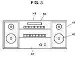
- Fig. 3 is an outside view showing an audio minicomponent system in accordance with one exemplary embodiment of the present invention.
- a loudspeaker system is configured by incorporating loudspeaker 40 into enclosure 41.
- Minicomponent system 44 includes amplifier 42 for amplifying electric signals input into this loudspeaker and player 43 for outputting a source input into amplifier 42.
- Fig. 4 is a sectional view showing automobile 50 that is a device having a mobile means in accordance with one exemplary embodiment of the present invention.
- automobile 50 is configured by incorporating loudspeaker 40 of the present invention into a rear tray.
- the damper has flexibility because a resin layer provided on the surface of the damper base material contains a flexibility imparting agent.
- a resin layer provided on the surface of the damper base material contains a flexibility imparting agent.
Landscapes
- Engineering & Computer Science (AREA)
- Physics & Mathematics (AREA)
- Acoustics & Sound (AREA)
- Signal Processing (AREA)
- Multimedia (AREA)
- Audible-Bandwidth Dynamoelectric Transducers Other Than Pickups (AREA)
Applications Claiming Priority (2)
| Application Number | Priority Date | Filing Date | Title |
|---|---|---|---|
| JP2005015084A JP2006203728A (ja) | 2005-01-24 | 2005-01-24 | スピーカ用ダンパーおよびその製造方法とこれを用いたスピーカおよび電子機器、装置 |
| PCT/JP2006/300936 WO2006078008A1 (ja) | 2005-01-24 | 2006-01-23 | スピーカ用ダンパおよびその製造方法とこれを用いたスピーカおよび電子機器、装置 |
Publications (2)
| Publication Number | Publication Date |
|---|---|
| EP1843629A1 true EP1843629A1 (de) | 2007-10-10 |
| EP1843629A4 EP1843629A4 (de) | 2008-05-28 |
Family
ID=36692380
Family Applications (1)
| Application Number | Title | Priority Date | Filing Date |
|---|---|---|---|
| EP06712152A Withdrawn EP1843629A4 (de) | 2005-01-24 | 2006-01-23 | Lautsprecherdämpfer, herstellungsverfahren dafür sowie lautsprecher und elektronische vorrichtung damit |
Country Status (5)
| Country | Link |
|---|---|
| US (1) | US8098869B2 (de) |
| EP (1) | EP1843629A4 (de) |
| JP (1) | JP2006203728A (de) |
| CN (1) | CN101107877A (de) |
| WO (1) | WO2006078008A1 (de) |
Cited By (1)
| Publication number | Priority date | Publication date | Assignee | Title |
|---|---|---|---|---|
| TWI669002B (zh) * | 2018-05-02 | 2019-08-11 | 陳元森 | Horn horn vibrating sheet manufacturing method for reducing material elasticity |
Families Citing this family (9)
| Publication number | Priority date | Publication date | Assignee | Title |
|---|---|---|---|---|
| JP2008205974A (ja) * | 2007-02-21 | 2008-09-04 | Sony Corp | スピーカ用振動板 |
| US8315420B2 (en) * | 2007-02-28 | 2012-11-20 | Bose Corporation | Spider |
| US8813906B2 (en) * | 2012-10-16 | 2014-08-26 | Hiroshi Ohara | Speaker damper and manufacturing method of the same |
| CN105323696A (zh) * | 2014-07-14 | 2016-02-10 | B.O.B.股份有限公司 | 喇叭振动片及其放电处理模制方法 |
| CN105282676A (zh) * | 2014-07-14 | 2016-01-27 | B.O.B.股份有限公司 | 喇叭振动片及其难燃处理模制方法 |
| CN105282677B (zh) * | 2014-07-14 | 2019-10-22 | B.O.B.股份有限公司 | 喇叭振动片拨水处理模制方法 |
| CN106658274B (zh) * | 2016-12-30 | 2023-12-12 | 深圳市君兰电子有限公司 | 一种喷泉水箱超声工艺生产方法及带喷泉灯效的音箱 |
| JP6820535B2 (ja) * | 2017-03-16 | 2021-01-27 | パナソニックIpマネジメント株式会社 | スピーカ用振動板およびこれを用いたスピーカ |
| US11530732B2 (en) * | 2019-04-02 | 2022-12-20 | Raytheon Company | Method of fabricating thin form factor vibration isolators with stable storage modulus properties over extended temperature ranges as standalone parts |
Family Cites Families (16)
| Publication number | Priority date | Publication date | Assignee | Title |
|---|---|---|---|---|
| JPS50117411A (de) * | 1974-01-29 | 1975-09-13 | ||
| JPS5324826A (en) | 1976-08-20 | 1978-03-08 | Foster Electric Co Ltd | Speaker damper |
| JPS5787698A (en) * | 1980-11-20 | 1982-06-01 | Onkyo Corp | Damper for speaker |
| JPS6443000A (en) * | 1987-08-10 | 1989-02-15 | Foster Electric Co Ltd | Manufacture of damper of speaker |
| JP3005099B2 (ja) * | 1991-12-10 | 2000-01-31 | フオスター電機株式会社 | 電気音響変換器 |
| JP3287750B2 (ja) | 1995-02-23 | 2002-06-04 | 帝人株式会社 | スピーカー用ダンパーおよびその製造方法 |
| EP0729289B1 (de) | 1995-02-23 | 1998-07-22 | Teijin Limited | Lautsprecherdämpfer und Verfahren zu dessen Herstellung |
| US5945643A (en) * | 1995-06-16 | 1999-08-31 | Casser; Donald J. | Vibration dampening material and process |
| JP3698574B2 (ja) | 1997-12-12 | 2005-09-21 | 電気化学工業株式会社 | 接着剤組成物、接合体、スピーカー及び接着方法 |
| JP2000080179A (ja) * | 1998-09-03 | 2000-03-21 | Toray Ind Inc | 熱可塑性樹脂シートの表面処理方法 |
| JP2000196533A (ja) | 1998-12-24 | 2000-07-14 | Kdd Kaitei Cable System Kk | 光伝送システム及び端局システム |
| JP2003078993A (ja) | 2001-08-31 | 2003-03-14 | Pioneer Electronic Corp | スピーカ用ダンパー |
| JP4285988B2 (ja) | 2002-12-20 | 2009-06-24 | 東芝エレベータ株式会社 | エレベータの釣合いおもり装置 |
| JP4795712B2 (ja) * | 2005-04-21 | 2011-10-19 | パイオニア株式会社 | スピーカー装置用振動系部品及びその製造方法 |
| JP4623000B2 (ja) * | 2006-01-17 | 2011-02-02 | 日本ビクター株式会社 | 電気音響変換器用振動板の製造方法 |
| JP4505690B2 (ja) * | 2008-02-27 | 2010-07-21 | オンキヨー株式会社 | スピーカー |
-
2005
- 2005-01-24 JP JP2005015084A patent/JP2006203728A/ja active Pending
-
2006
- 2006-01-23 US US11/813,681 patent/US8098869B2/en active Active
- 2006-01-23 WO PCT/JP2006/300936 patent/WO2006078008A1/ja not_active Ceased
- 2006-01-23 EP EP06712152A patent/EP1843629A4/de not_active Withdrawn
- 2006-01-23 CN CNA2006800030829A patent/CN101107877A/zh active Pending
Cited By (1)
| Publication number | Priority date | Publication date | Assignee | Title |
|---|---|---|---|---|
| TWI669002B (zh) * | 2018-05-02 | 2019-08-11 | 陳元森 | Horn horn vibrating sheet manufacturing method for reducing material elasticity |
Also Published As
| Publication number | Publication date |
|---|---|
| CN101107877A (zh) | 2008-01-16 |
| US8098869B2 (en) | 2012-01-17 |
| JP2006203728A (ja) | 2006-08-03 |
| US20090010471A1 (en) | 2009-01-08 |
| WO2006078008A1 (ja) | 2006-07-27 |
| EP1843629A4 (de) | 2008-05-28 |
Similar Documents
| Publication | Publication Date | Title |
|---|---|---|
| EP1843629A1 (de) | Lautsprecherdämpfer, herstellungsverfahren dafür sowie lautsprecher und elektronische vorrichtung damit | |
| US8284964B2 (en) | Compound membrane, method of manufacturing the same, and acoustic device | |
| EP0860833B1 (de) | Rahmen-Dämpfungsvorrichtung | |
| EP1715720B1 (de) | Teil des Vibrationssystems eines Lautsprechers und Herstellungsmethode | |
| CN101039531A (zh) | 扬声器 | |
| CN207968945U (zh) | 碳纤维球顶及扬声器 | |
| US5848174A (en) | Linear movement speaker system | |
| EP2692146B1 (de) | Schalldämpfungselemente aus monofilamentgewebe | |
| KR20230101875A (ko) | 음향발생장치에 적용 가능한 진동막 및 이의 제조방법, 음향발생장치 | |
| US5719946A (en) | Loudspeaker for higher audio frequencies and a manufacturing method thereof | |
| US20060266578A1 (en) | Speaker diaphragm and method for manufacturing the same | |
| KR101886166B1 (ko) | 방수 통음 시트 | |
| CN105282677B (zh) | 喇叭振动片拨水处理模制方法 | |
| US20050232457A1 (en) | Speaker-use diaphragm and speaker | |
| US6772855B2 (en) | Damper for speaker and method of producing the same | |
| EP0624048A1 (de) | Anordnung zum Stützen eines Schwingsystems in einem Lautsprecher | |
| JP2006041984A (ja) | スピーカ用エッジの製造方法およびスピーカ用エッジならびにこれを用いたスピーカ用振動板およびスピーカ、電子機器、装置 | |
| US20010017231A1 (en) | Speaker | |
| CN105282676A (zh) | 喇叭振动片及其难燃处理模制方法 | |
| KR100313136B1 (ko) | 센터캡과댐퍼가일체로형성된마이크로스피커및그의제조방법 | |
| JP2004229173A (ja) | スピーカ用ダンパー及びその製造方法ならびにこれを用いたスピーカ | |
| JPS62263799A (ja) | スピ−カ用ダンパ− | |
| CN115134721B (zh) | 球顶及其制备方法、振膜组件、发声装置和电子设备 | |
| JPS5931112Y2 (ja) | スピ−カ−用コルゲ−ションダンパ− | |
| KR20160127205A (ko) | 내구성이 우수한 스피커용 댐퍼 및 그 제조 방법 |
Legal Events
| Date | Code | Title | Description |
|---|---|---|---|
| PUAI | Public reference made under article 153(3) epc to a published international application that has entered the european phase |
Free format text: ORIGINAL CODE: 0009012 |
|
| 17P | Request for examination filed |
Effective date: 20070416 |
|
| AK | Designated contracting states |
Kind code of ref document: A1 Designated state(s): DE FR GB |
|
| DAX | Request for extension of the european patent (deleted) | ||
| RBV | Designated contracting states (corrected) |
Designated state(s): DE FR GB |
|
| A4 | Supplementary search report drawn up and despatched |
Effective date: 20080428 |
|
| RAP1 | Party data changed (applicant data changed or rights of an application transferred) |
Owner name: PANASONIC CORPORATION |
|
| 17Q | First examination report despatched |
Effective date: 20140722 |
|
| STAA | Information on the status of an ep patent application or granted ep patent |
Free format text: STATUS: THE APPLICATION IS DEEMED TO BE WITHDRAWN |
|
| 18D | Application deemed to be withdrawn |
Effective date: 20141202 |