EP1843652B1 - Abdeckvorrichtung für den vorderen Bereich einer Luftdurchtrittseinrichtung sowie Luftdurchtrittseinrichtung - Google Patents
Abdeckvorrichtung für den vorderen Bereich einer Luftdurchtrittseinrichtung sowie Luftdurchtrittseinrichtung Download PDFInfo
- Publication number
- EP1843652B1 EP1843652B1 EP07006486A EP07006486A EP1843652B1 EP 1843652 B1 EP1843652 B1 EP 1843652B1 EP 07006486 A EP07006486 A EP 07006486A EP 07006486 A EP07006486 A EP 07006486A EP 1843652 B1 EP1843652 B1 EP 1843652B1
- Authority
- EP
- European Patent Office
- Prior art keywords
- lamellar
- cover
- shape
- air passage
- elements
- Prior art date
- Legal status (The legal status is an assumption and is not a legal conclusion. Google has not performed a legal analysis and makes no representation as to the accuracy of the status listed.)
- Active
Links
Images




Classifications
-
- B—PERFORMING OPERATIONS; TRANSPORTING
- B01—PHYSICAL OR CHEMICAL PROCESSES OR APPARATUS IN GENERAL
- B01D—SEPARATION
- B01D46/00—Filters or filtering processes specially modified for separating dispersed particles from gases or vapours
- B01D46/0002—Casings; Housings; Frame constructions
- B01D46/0004—Details of removable closures, lids, caps or filter heads
-
- B—PERFORMING OPERATIONS; TRANSPORTING
- B01—PHYSICAL OR CHEMICAL PROCESSES OR APPARATUS IN GENERAL
- B01D—SEPARATION
- B01D46/00—Filters or filtering processes specially modified for separating dispersed particles from gases or vapours
- B01D46/0027—Filters or filtering processes specially modified for separating dispersed particles from gases or vapours with additional separating or treating functions
-
- B—PERFORMING OPERATIONS; TRANSPORTING
- B01—PHYSICAL OR CHEMICAL PROCESSES OR APPARATUS IN GENERAL
- B01D—SEPARATION
- B01D46/00—Filters or filtering processes specially modified for separating dispersed particles from gases or vapours
- B01D46/42—Auxiliary equipment or operation thereof
-
- F—MECHANICAL ENGINEERING; LIGHTING; HEATING; WEAPONS; BLASTING
- F04—POSITIVE - DISPLACEMENT MACHINES FOR LIQUIDS; PUMPS FOR LIQUIDS OR ELASTIC FLUIDS
- F04D—NON-POSITIVE-DISPLACEMENT PUMPS
- F04D29/00—Details, component parts, or accessories
- F04D29/70—Suction grids; Strainers; Dust separation; Cleaning
- F04D29/701—Suction grids; Strainers; Dust separation; Cleaning especially adapted for elastic fluid pumps
- F04D29/703—Suction grids; Strainers; Dust separation; Cleaning especially adapted for elastic fluid pumps specially for fans, e.g. fan guards
-
- H—ELECTRICITY
- H05—ELECTRIC TECHNIQUES NOT OTHERWISE PROVIDED FOR
- H05K—PRINTED CIRCUITS; CASINGS OR CONSTRUCTIONAL DETAILS OF ELECTRIC APPARATUS; MANUFACTURE OF ASSEMBLAGES OF ELECTRICAL COMPONENTS
- H05K7/00—Constructional details common to different types of electric apparatus
- H05K7/20—Modifications to facilitate cooling, ventilating, or heating
- H05K7/20009—Modifications to facilitate cooling, ventilating, or heating using a gaseous coolant in electronic enclosures
- H05K7/20136—Forced ventilation, e.g. by fans
- H05K7/20181—Filters; Louvers
Definitions
- the invention relates to a covering device for the front region of an air passage device according to the preamble of claim 1 and an air passage device.
- Such a covering device as it is in DE 200 02 124 U is sometimes referred to as a cover, as a cover plate, as a cover plate or as a "design cover" is usually upstream of the front portion of a filter fan.
- a cover As a cover plate, as a cover plate or as a "design cover” is usually upstream of the front portion of a filter fan.
- the cover In the course of the fact that such a filter fan sucks in its operation (ambient) air through a filter mat, it can not be avoided that the cover also located in the (ambient) air liquid particles or drops of liquid - rain drops for outdoor use of the Filter fan - sucks. Consequently, liquid and substances of a liquid-like consistency inevitably accumulate in the region of the covering device, in particular in the area between the covering device and the filter ventilator.
- each lamellar element has in its upper region a section with a hook-like shape directed counter to the air inflow.
- the portion with the hook-like shape extends over the length of the lamellar element.
- the lamellar elements are arranged relative to one another such that the lamellar elements overlap in sections, the lower region of each lamellar element lying on a below the section with the hook-like shape extending horizontal plane E or on a above the section with the hook-like shape extending horizontal plane E1 or in an area between the two levels E and E1.
- the covering device consists of a frame-like housing for receiving the filter mat and a design cover which is fixed, releasably or pivotably held in the housing and covers the filter mat, which comprises at least two lateral holding elements which extend in a longitudinal direction, preferably cheek-shaped , between which a plurality of lamellar elements are arranged, which are arranged at a distance from each other with simultaneous segmental overlap and such arranged obliquely are arranged, that the respective front and outer blade edges are located lower than the rear blade edges, wherein the upper, rear blade edges of a preferably arcuate configuration having lamellar elements have barb-like design.
- the individual lamellar elements are arranged relative to one another in such a way that a high optical coverage and a privacy on the filter mat is obtained with optimum air permeability.
- each slat element has rounded, front slat edges.
- the invention provides that the barb-like shape having rear lamellar edge of each blade element has a cross-sectional shape which corresponds approximately to the shape of a semicircle with a front projecting portion.
- a further embodiment of the invention consists in that the area of the front lamellar edge of each lamellar element has a material reinforcement, so that the lower-lying front marginal edge region of each lamellar element has a greater thickness compared to the rear and higher marginal edge region.
- cover Due to the inventive design of the cover is achieved, in particular by the shape of the individual fin elements that sucked by the fan of the filter fan dust and water are at least partially retained by the lamellar elements. Water impinging on the cover device runs to the outside for the most part, so that the filter mat is wetted only slightly or little by the water.
- the invention further relates to an air passage device, such as filter fan or outlet filter, for installation in an opening in a wall of a housing, in particular a housing with waste heat generating components, an electronics cabinet, a cabinet, a housing system or a computer system, with a Covering device, in particular for covering the front region of the air passage device, and for the filter mat of the air passage device, wherein the cover device comprises a design cover covering the filter mat with a number of inclined lamellar elements, wherein each lamellar element in its upper region a directed against the air inflow portion with a hook-like Shaping has.
- an air passage device such as filter fan or outlet filter
- the portion with the hook-like shape extends over the length of the lamellar element.
- the lamellar elements are arranged relative to one another in such a way that the lamellar elements overlap in sections, the lower region of each lamellar element lying on a horizontal plane E extending below the section with the hook-like shaping or on a horizontal plane E 1 or E 1 above the section with the hook-like shaping lies in an area between the two levels E and E1.
- air passage device 200 can be used in conjunction with a fan or fan as a filter fan and without fan 20 as an outlet filter.
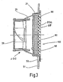
- the air passage device 200 is used in housings of waste heat generating components, such as cabinets, electronic cabinets, computer system o. The like., In which the air passage device 200 is installed in mounting apertures 50 in a wall 59 of such a housing ( Fig. 3 ).
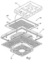
- the essential components of the air passage device 200 are a fan grille which is designed as a design cover 80 with ventilation slots and the cover device 100 according to the invention, a base housing 21, a fan carrier 25 for the blower 26 and the blower 26 when the air passage device 200 is used as a filter fan ( Fig. 1 to 3 ).
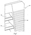
- the cover device 100 which forms the fan grille, is designed as a design cover 80 and consists of a frame-like housing 30 with lamellar elements 90, wherein 90 ventilation slots are formed between the sectionally overlapping lamella elements.
- the filter mat 60 may be held on the inner wall surface of the design cover 80 ( Fig. 3 ) or it is inserted in the basic housing.
- the louver elements 90 are held in holding elements 81, 82, which form the frame of the design cover 80.
- the cover device 100 consists of a frame-like housing 30 for receiving the filter mat 60 and a fixed, releasably or pivotally held in the housing 30 and the filter mat 60 covering design cover 80.
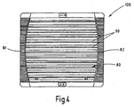
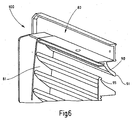
- This design cover 80 includes at least two lateral, extending in a longitudinal direction L edge, preferably cheek-shaped holding elements 81, 82, between which the lamellar elements 90 are arranged ( Fig. 4 and 5 ).
- the lamellar elements 90 are at the same time in sections overlapping in one Spaced apart from each other and placed so inclined that the respective front and outer blade edges 91 are located lower than the rear blade edges 92.
- the upper rear lamella edges 92 of the lamellar elements 90 having an arcuate configuration have barb-like or hook-like shapes 95 (FIG. Fig. 6 to 8 . 8A and 9 ).
- the section 90 'with the hook-like shape 95 extends over the length of the lamellar element 90.
- the lamellar elements 90 are arranged relative to each other such that overlap the lamellar elements in sections, wherein the respective lower portion 90b of each lamellar element on a below the section 90th lying with the hook-like shape extending horizontal plane E or on a above the portion 90 'with the hook-like shape 95 extending horizontal plane E1 or in a region between the two planes E and E1.
- the individual fin elements 90 are further arranged to each other such that a high optical coverage and a privacy on the filter mat 60 is obtained with optimum air permeability.
- each lamellar element 90 has rounded, demanding longitudinal edge edges 96.
- the barb-like shape 95 having the rear sipe edge 92 of each fin element 90 has a cross-sectional shape which corresponds approximately to the shape of a semicircle with a front projecting portion 95 a.
- the area of the front sipe edge 91 of each slat element 90 has a material reinforcement 97, so that the lower-lying front edge edge portion 91 a of each slat element relative to the rear and higher edge edge region 92 a has a greater thickness. Due to this configuration, each lamella element 90 has an arcuate running surface which terminates in the upper region of each lamella element in the barb-like lamellar design. In this way, the fan of the air passage device 200 sucked water is retained by the barb-like shape 95 of the individual fin elements 90 and thus drips down from or individual accumulating droplets grow and then run off to the front.
- the design cover 80 with its fin elements 90 is preferably made of a plastic or other suitable material.
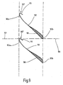
- Fig. 9 two superimposed lamellar elements 90 are shown, which are arranged to each other such that there is an overlap.
- the lamellar elements 90 are formed extending approximately S-shaped, wherein in the front bent portion 90b of each fin element material replenishment 98 is provided, whereby an aerodynamic area is created, because without this measure, it can lead to air flow losses.
- the upper portion 90a of each fin member 90 has the hook-like shape 95.
- the respective overlapping region of two lamellar elements 90 is indicated at 99.
- Each lamella element 90 may be in one piece ( Fig. 4 ) or two-part ( Fig. 5 ) or consist of several equal or unequal length sections.
Landscapes
- Engineering & Computer Science (AREA)
- Chemical Kinetics & Catalysis (AREA)
- Chemical & Material Sciences (AREA)
- Microelectronics & Electronic Packaging (AREA)
- Physics & Mathematics (AREA)
- General Engineering & Computer Science (AREA)
- Mechanical Engineering (AREA)
- Thermal Sciences (AREA)
- Filtering Of Dispersed Particles In Gases (AREA)
- Cooling Or The Like Of Electrical Apparatus (AREA)
- Compressor (AREA)
- Air-Flow Control Members (AREA)
- Air-Conditioning For Vehicles (AREA)
- General Details Of Gearings (AREA)
Applications Claiming Priority (1)
| Application Number | Priority Date | Filing Date | Title |
|---|---|---|---|
| DE202006005673U DE202006005673U1 (de) | 2006-04-05 | 2006-04-05 | Abdeckvorrichtung für den vorderen Bereich einer Luftdurchtrittseinrichtung sowie Luftdurchtrittseinrichtung |
Publications (3)
| Publication Number | Publication Date |
|---|---|
| EP1843652A2 EP1843652A2 (de) | 2007-10-10 |
| EP1843652A3 EP1843652A3 (de) | 2009-05-20 |
| EP1843652B1 true EP1843652B1 (de) | 2009-10-28 |
Family
ID=36600093
Family Applications (1)
| Application Number | Title | Priority Date | Filing Date |
|---|---|---|---|
| EP07006486A Active EP1843652B1 (de) | 2006-04-05 | 2007-03-29 | Abdeckvorrichtung für den vorderen Bereich einer Luftdurchtrittseinrichtung sowie Luftdurchtrittseinrichtung |
Country Status (7)
| Country | Link |
|---|---|
| US (1) | US10173161B2 (es) |
| EP (1) | EP1843652B1 (es) |
| CN (1) | CN101050783B (es) |
| AT (1) | ATE447317T1 (es) |
| DE (2) | DE202006005673U1 (es) |
| ES (1) | ES2335041T3 (es) |
| RU (1) | RU2340837C1 (es) |
Cited By (3)
| Publication number | Priority date | Publication date | Assignee | Title |
|---|---|---|---|---|
| USD851742S1 (en) | 2016-09-20 | 2019-06-18 | Hoffman Enclosures, Inc. | Support for a fan shroud |
| USD859631S1 (en) | 2016-09-20 | 2019-09-10 | Hoffman Enclosures, Inc. | Fan shroud |
| EP4656270A1 (en) | 2024-05-27 | 2025-12-03 | Fandis S.p.A. | Air filtering device for ventilation units of industrial electric cabinets |
Families Citing this family (14)
| Publication number | Priority date | Publication date | Assignee | Title |
|---|---|---|---|---|
| US7958733B2 (en) | 2006-06-20 | 2011-06-14 | The United States Of America As Represented By The Administrator Of The National Aeronautics And Space Administration | Jet engine exhaust nozzle flow effector |
| US7594800B2 (en) * | 2006-07-31 | 2009-09-29 | General Electric Company | Ventilation assembly for wind turbine rotor hub |
| DE202006015789U1 (de) * | 2006-10-12 | 2006-12-07 | Pfannenberg Gmbh | Luftdurchtrittsvorrichtung mit Steuerungselement |
| IT1393780B1 (it) * | 2009-04-17 | 2012-05-08 | Fandis S P A | Scatola portafiltro perfezionata |
| DE102010016504B4 (de) * | 2010-04-19 | 2014-05-15 | Rittal Gmbh & Co. Kg | Filtereinheit für einen Schaltschrank |
| DE102010016505A1 (de) * | 2010-04-19 | 2011-10-20 | Rittal Gmbh & Co. Kg | Lamellengitter |
| DE102010052049A1 (de) | 2010-11-23 | 2012-05-24 | Rübsamen & Herr Elektrobau GmbH | Dachlüfter und Dachentlüftung |
| US20140141708A1 (en) * | 2012-11-21 | 2014-05-22 | Dnkb, Inc. | Ventilation Systems and Related Methods |
| GB2547264A (en) * | 2016-02-12 | 2017-08-16 | New World Energy Entpr Ltd | A fluid actuated vent |
| US10512866B2 (en) | 2016-02-16 | 2019-12-24 | Hoffman Enclosures, Inc. | Filter housing for filter fan |
| JP6493427B2 (ja) * | 2016-05-11 | 2019-04-03 | 株式会社デンソー | ファンシュラウド |
| EP3813500B1 (de) | 2019-10-24 | 2023-09-20 | Andreas Stihl AG & Co. KG | Lüftungsvorrichtung mit spritzwasserschutz und arbeitsgerät mit einer solchen lüftungsvorrichtung |
| RU2740049C1 (ru) * | 2020-07-01 | 2020-12-31 | Николай Александрович Туленинов | Вентиляционная решетка системы вентиляции здания (варианты) |
| CN116428683B (zh) * | 2023-05-29 | 2023-11-14 | 宁波市海创环能科技有限公司 | 一种多重过滤式空气净化器及净化方法 |
Family Cites Families (31)
| Publication number | Priority date | Publication date | Assignee | Title |
|---|---|---|---|---|
| US903340A (en) * | 1907-08-12 | 1908-11-10 | Miles Townsend | Ventilator. |
| US2194388A (en) * | 1937-12-31 | 1940-03-19 | Haugh Walter | Window ventilator |
| US2575499A (en) * | 1949-03-10 | 1951-11-20 | Max S Manow | Removable fibre glass filter |
| US2842042A (en) * | 1955-12-09 | 1958-07-08 | George Munday | Ventilator wall and window blocks |
| US2962956A (en) * | 1957-09-16 | 1960-12-06 | Acorn Advertisers | Ventilating louver assembly |
| GB1329862A (en) * | 1970-09-22 | 1973-09-12 | Sound Attenuators Ltd | Acoustic attenuator |
| US3968738A (en) * | 1974-04-29 | 1976-07-13 | Champion International Corporation | Plastic louver frame assembly |
| SU821858A1 (ru) | 1978-11-10 | 1981-04-15 | Центральный Научно-Исследовательскийи Проектно-Конструкторский Институтпрофилактики Пневмокониозов Итехники Безопасности Цниипп | Вентил ционный насадок |
| IT1118938B (it) * | 1979-10-05 | 1986-03-03 | Fiat Ricerche | Persiana di ventilazione comprendente una pluralita di lamelle profilate |
| SU994871A2 (ru) | 1981-08-07 | 1983-02-07 | Центральный научно-исследовательский и проектно-конструкторский институт профилактики пневмокониозов и техники безопасности | Вентил ционный насадок |
| CH659879A5 (en) * | 1983-03-09 | 1987-02-27 | Schmidlin Ag | Weather-protection grating for ducts opening in external walls |
| NO160162C (no) * | 1986-09-18 | 1989-03-15 | Norsk Hydro As | Anordning ved ventilasjonsvegg eller louver. |
| DE8701865U1 (de) * | 1987-02-07 | 1987-07-23 | Bielefelder Küchenmaschinen- und Transportgerätefabrik vom Braucke GmbH, 4800 Bielefeld | Vorrichtung zum Aufhängen von Geräten mit Stielen |
| GB2211598B (en) * | 1987-10-17 | 1991-06-05 | Steelpress | Louvre blade |
| FI85188C (fi) | 1990-03-12 | 1992-03-10 | Jorma Koenoenen | Foerfarande och arrangemang foer att daempa tonen och/eller foer att reglera stroemningen i ett stroemningssystem foer ett gasformigt medelaemne, saosom t.ex. i ett luftbehandlingssystems luftdistributions- och/eller avluftningssystem, samt anvaendning av en modulljuddaempare. |
| RU1771527C (ru) | 1991-03-25 | 1992-10-23 | Алексей Александрович Колмаков | Регулируема решетка |
| US5163871A (en) * | 1991-04-02 | 1992-11-17 | Robert Huibregtse | Floor register grill |
| SE9303002L (sv) | 1993-09-15 | 1995-03-16 | Otto Andersson | Anordning för montage av ventilationskanaler och filter med filterhållare samt metoder i samband med montage och byte av filter |
| DE19525850C1 (de) * | 1995-07-15 | 1996-08-14 | Loh Kg Rittal Werk | HF-dicht in den Durchbruch einer Montageplatte eingebauter Filterlüfter |
| US6226922B1 (en) * | 1998-04-30 | 2001-05-08 | Ronald L. Swapp | Window shutter |
| DE20002124U1 (de) * | 2000-02-07 | 2000-04-13 | Otto Pfannenberg Elektro-Spezialgerätebau GmbH, 21035 Hamburg | Luftdurchtrittseinrichtung |
| DE10038821C2 (de) * | 2000-07-11 | 2003-02-20 | Siemens Ag | Lüftungsgitter |
| US6378262B1 (en) * | 2000-09-12 | 2002-04-30 | Robert Mercadante | Telescoping louvered window insert |
| US6690576B2 (en) * | 2001-07-31 | 2004-02-10 | Hewlett Packard Development Company, L.P. | Externally mounted on-line replaceable fan module |
| US6817940B2 (en) * | 2002-06-03 | 2004-11-16 | Pfannenberg Gmbh | Airflow unit |
| RU27948U1 (ru) | 2002-08-14 | 2003-02-27 | Зинин Александр Юрьевич | Вентилятор-воздухоочиститель |
| US6902597B2 (en) * | 2003-03-20 | 2005-06-07 | Whirlpool Corporation | Floor standing treatment device |
| USD512503S1 (en) * | 2004-04-02 | 2005-12-06 | Broan-Nutone Llc | Fan grille |
| JP4521759B2 (ja) * | 2004-11-26 | 2010-08-11 | 株式会社リコー | 排気装置及びその排気装置を有する画像形成装置 |
| ATE450306T1 (de) * | 2006-07-13 | 2009-12-15 | Pfannenberg Gmbh | Luftdurchtrittsvorrichtung |
| AU2006350946B2 (en) * | 2006-11-17 | 2012-01-19 | Ramsay, Linda | Static roof ventilator |
-
2006
- 2006-04-05 DE DE202006005673U patent/DE202006005673U1/de not_active Expired - Lifetime
-
2007
- 2007-03-29 DE DE502007001825T patent/DE502007001825D1/de active Active
- 2007-03-29 ES ES07006486T patent/ES2335041T3/es active Active
- 2007-03-29 EP EP07006486A patent/EP1843652B1/de active Active
- 2007-03-29 AT AT07006486T patent/ATE447317T1/de active
- 2007-03-30 US US11/731,808 patent/US10173161B2/en active Active
- 2007-04-04 RU RU2007112580/06A patent/RU2340837C1/ru active
- 2007-04-05 CN CN2007101053364A patent/CN101050783B/zh active Active
Cited By (3)
| Publication number | Priority date | Publication date | Assignee | Title |
|---|---|---|---|---|
| USD851742S1 (en) | 2016-09-20 | 2019-06-18 | Hoffman Enclosures, Inc. | Support for a fan shroud |
| USD859631S1 (en) | 2016-09-20 | 2019-09-10 | Hoffman Enclosures, Inc. | Fan shroud |
| EP4656270A1 (en) | 2024-05-27 | 2025-12-03 | Fandis S.p.A. | Air filtering device for ventilation units of industrial electric cabinets |
Also Published As
| Publication number | Publication date |
|---|---|
| EP1843652A2 (de) | 2007-10-10 |
| US20080014858A1 (en) | 2008-01-17 |
| ATE447317T1 (de) | 2009-11-15 |
| DE502007001825D1 (de) | 2009-12-10 |
| DE202006005673U1 (de) | 2006-06-08 |
| US10173161B2 (en) | 2019-01-08 |
| ES2335041T3 (es) | 2010-03-18 |
| CN101050783A (zh) | 2007-10-10 |
| CN101050783B (zh) | 2010-11-03 |
| RU2340837C1 (ru) | 2008-12-10 |
| EP1843652A3 (de) | 2009-05-20 |
Similar Documents
| Publication | Publication Date | Title |
|---|---|---|
| EP1843652A2 (de) | Abdeckvorrichtung für den vorderen Bereich einer Luftdurchtrittseinrichtung sowie Luftdurchtrittseinrichtung | |
| DE19804904C1 (de) | Schaltschrank mit Einrichtungen zum Kühlen der Innenraum-Warmluft | |
| DE19827449B4 (de) | Lüftereinheit für einen Luftreiniger | |
| EP2561740B1 (de) | Lamellengitter | |
| EP3255281A1 (de) | Ventilator mit tandemnachleitschaufeln | |
| EP0190794A2 (de) | Einbau-Kühlschrank | |
| DE19734146A1 (de) | Luftzuführeinrichtung | |
| DE19511158A1 (de) | Ventilatoreinheit für Reinräume | |
| DE102009059836A1 (de) | Filtereinheit für eine Dunstabzugshaube und Dunstabzugshaube | |
| DE2103593C2 (de) | Dunstabzugshaube für Küchen | |
| EP3620721B1 (de) | Vorrichtung zur muldenabsaugung von auf einem kochfeld erzeugter abluft | |
| EP2286153B1 (de) | Umluftweiche | |
| EP2772695B1 (de) | Dunstabzugshaube | |
| EP1622497B1 (de) | Ausblasfilter mit luftleitdach | |
| DE102011018962C5 (de) | Kochfeld mit zentraler Absaugung von Kochdünsten nach unten | |
| EP3222919B1 (de) | Dunstabzugshaube mit sichthaube und innenelement | |
| EP2787870A2 (de) | Grillgerät | |
| DE19715516C1 (de) | Lüftungsgitter | |
| DE3241860C3 (de) | Radialventilator | |
| WO2007000444A2 (de) | Heizung und/oder kühlung eines raumes | |
| EP2484262B1 (de) | Saugleiste zum Absaugen eines Untergrunds | |
| DE4115919A1 (de) | Lufteintrittsgehaeuse | |
| DE8714894U1 (de) | Lüftereinsatz für die Kühlung elektrischer bzw. elektronischer Baugruppen | |
| EP0070870A1 (de) | Einrichtung zum absaugen von farbnebeln. | |
| DE9114775U1 (de) | Wärmeaustauscher |
Legal Events
| Date | Code | Title | Description |
|---|---|---|---|
| PUAI | Public reference made under article 153(3) epc to a published international application that has entered the european phase |
Free format text: ORIGINAL CODE: 0009012 |
|
| AK | Designated contracting states |
Kind code of ref document: A2 Designated state(s): AT BE BG CH CY CZ DE DK EE ES FI FR GB GR HU IE IS IT LI LT LU LV MC MT NL PL PT RO SE SI SK TR |
|
| AX | Request for extension of the european patent |
Extension state: AL BA HR MK YU |
|
| PUAL | Search report despatched |
Free format text: ORIGINAL CODE: 0009013 |
|
| AK | Designated contracting states |
Kind code of ref document: A3 Designated state(s): AT BE BG CH CY CZ DE DK EE ES FI FR GB GR HU IE IS IT LI LT LU LV MC MT NL PL PT RO SE SI SK TR |
|
| AX | Request for extension of the european patent |
Extension state: AL BA HR MK RS |
|
| RIC1 | Information provided on ipc code assigned before grant |
Ipc: F04D 29/70 20060101ALI20090414BHEP Ipc: F04D 25/12 20060101ALI20090414BHEP Ipc: H05K 7/20 20060101AFI20070801BHEP |
|
| 17P | Request for examination filed |
Effective date: 20090425 |
|
| GRAP | Despatch of communication of intention to grant a patent |
Free format text: ORIGINAL CODE: EPIDOSNIGR1 |
|
| GRAS | Grant fee paid |
Free format text: ORIGINAL CODE: EPIDOSNIGR3 |
|
| GRAA | (expected) grant |
Free format text: ORIGINAL CODE: 0009210 |
|
| AK | Designated contracting states |
Kind code of ref document: B1 Designated state(s): AT BE BG CH CY CZ DE DK EE ES FI FR GB GR HU IE IS IT LI LT LU LV MC MT NL PL PT RO SE SI SK TR |
|
| REG | Reference to a national code |
Ref country code: GB Ref legal event code: FG4D Free format text: NOT ENGLISH |
|
| REG | Reference to a national code |
Ref country code: CH Ref legal event code: EP |
|
| REG | Reference to a national code |
Ref country code: IE Ref legal event code: FG4D |
|
| REF | Corresponds to: |
Ref document number: 502007001825 Country of ref document: DE Date of ref document: 20091210 Kind code of ref document: P |
|
| AKX | Designation fees paid |
Designated state(s): AT BE BG CH CY CZ DE DK EE ES FI FR GB GR HU IE IS IT LI LT LU LV MC MT NL PL PT RO SE SI SK TR |
|
| REG | Reference to a national code |
Ref country code: ES Ref legal event code: FG2A Ref document number: 2335041 Country of ref document: ES Kind code of ref document: T3 |
|
| LTIE | Lt: invalidation of european patent or patent extension |
Effective date: 20091028 |
|
| NLV1 | Nl: lapsed or annulled due to failure to fulfill the requirements of art. 29p and 29m of the patents act | ||
| PG25 | Lapsed in a contracting state [announced via postgrant information from national office to epo] |
Ref country code: IS Free format text: LAPSE BECAUSE OF FAILURE TO SUBMIT A TRANSLATION OF THE DESCRIPTION OR TO PAY THE FEE WITHIN THE PRESCRIBED TIME-LIMIT Effective date: 20100228 Ref country code: SE Free format text: LAPSE BECAUSE OF FAILURE TO SUBMIT A TRANSLATION OF THE DESCRIPTION OR TO PAY THE FEE WITHIN THE PRESCRIBED TIME-LIMIT Effective date: 20091028 Ref country code: FI Free format text: LAPSE BECAUSE OF FAILURE TO SUBMIT A TRANSLATION OF THE DESCRIPTION OR TO PAY THE FEE WITHIN THE PRESCRIBED TIME-LIMIT Effective date: 20091028 Ref country code: PT Free format text: LAPSE BECAUSE OF FAILURE TO SUBMIT A TRANSLATION OF THE DESCRIPTION OR TO PAY THE FEE WITHIN THE PRESCRIBED TIME-LIMIT Effective date: 20100301 Ref country code: LT Free format text: LAPSE BECAUSE OF FAILURE TO SUBMIT A TRANSLATION OF THE DESCRIPTION OR TO PAY THE FEE WITHIN THE PRESCRIBED TIME-LIMIT Effective date: 20091028 |
|
| REG | Reference to a national code |
Ref country code: IE Ref legal event code: FD4D |
|
| PG25 | Lapsed in a contracting state [announced via postgrant information from national office to epo] |
Ref country code: LV Free format text: LAPSE BECAUSE OF FAILURE TO SUBMIT A TRANSLATION OF THE DESCRIPTION OR TO PAY THE FEE WITHIN THE PRESCRIBED TIME-LIMIT Effective date: 20091028 Ref country code: SI Free format text: LAPSE BECAUSE OF FAILURE TO SUBMIT A TRANSLATION OF THE DESCRIPTION OR TO PAY THE FEE WITHIN THE PRESCRIBED TIME-LIMIT Effective date: 20091028 Ref country code: CY Free format text: LAPSE BECAUSE OF FAILURE TO SUBMIT A TRANSLATION OF THE DESCRIPTION OR TO PAY THE FEE WITHIN THE PRESCRIBED TIME-LIMIT Effective date: 20091028 Ref country code: PL Free format text: LAPSE BECAUSE OF FAILURE TO SUBMIT A TRANSLATION OF THE DESCRIPTION OR TO PAY THE FEE WITHIN THE PRESCRIBED TIME-LIMIT Effective date: 20091028 |
|
| PG25 | Lapsed in a contracting state [announced via postgrant information from national office to epo] |
Ref country code: EE Free format text: LAPSE BECAUSE OF FAILURE TO SUBMIT A TRANSLATION OF THE DESCRIPTION OR TO PAY THE FEE WITHIN THE PRESCRIBED TIME-LIMIT Effective date: 20091028 Ref country code: BG Free format text: LAPSE BECAUSE OF FAILURE TO SUBMIT A TRANSLATION OF THE DESCRIPTION OR TO PAY THE FEE WITHIN THE PRESCRIBED TIME-LIMIT Effective date: 20100128 Ref country code: IE Free format text: LAPSE BECAUSE OF FAILURE TO SUBMIT A TRANSLATION OF THE DESCRIPTION OR TO PAY THE FEE WITHIN THE PRESCRIBED TIME-LIMIT Effective date: 20091028 Ref country code: DK Free format text: LAPSE BECAUSE OF FAILURE TO SUBMIT A TRANSLATION OF THE DESCRIPTION OR TO PAY THE FEE WITHIN THE PRESCRIBED TIME-LIMIT Effective date: 20091028 Ref country code: RO Free format text: LAPSE BECAUSE OF FAILURE TO SUBMIT A TRANSLATION OF THE DESCRIPTION OR TO PAY THE FEE WITHIN THE PRESCRIBED TIME-LIMIT Effective date: 20091028 |
|
| PG25 | Lapsed in a contracting state [announced via postgrant information from national office to epo] |
Ref country code: CZ Free format text: LAPSE BECAUSE OF FAILURE TO SUBMIT A TRANSLATION OF THE DESCRIPTION OR TO PAY THE FEE WITHIN THE PRESCRIBED TIME-LIMIT Effective date: 20091028 Ref country code: SK Free format text: LAPSE BECAUSE OF FAILURE TO SUBMIT A TRANSLATION OF THE DESCRIPTION OR TO PAY THE FEE WITHIN THE PRESCRIBED TIME-LIMIT Effective date: 20091028 |
|
| PLBE | No opposition filed within time limit |
Free format text: ORIGINAL CODE: 0009261 |
|
| STAA | Information on the status of an ep patent application or granted ep patent |
Free format text: STATUS: NO OPPOSITION FILED WITHIN TIME LIMIT |
|
| BERE | Be: lapsed |
Owner name: PFANNENBERG G.M.B.H. Effective date: 20100331 |
|
| 26N | No opposition filed |
Effective date: 20100729 |
|
| PG25 | Lapsed in a contracting state [announced via postgrant information from national office to epo] |
Ref country code: GR Free format text: LAPSE BECAUSE OF FAILURE TO SUBMIT A TRANSLATION OF THE DESCRIPTION OR TO PAY THE FEE WITHIN THE PRESCRIBED TIME-LIMIT Effective date: 20100129 Ref country code: MC Free format text: LAPSE BECAUSE OF NON-PAYMENT OF DUE FEES Effective date: 20100331 |
|
| PG25 | Lapsed in a contracting state [announced via postgrant information from national office to epo] |
Ref country code: BE Free format text: LAPSE BECAUSE OF NON-PAYMENT OF DUE FEES Effective date: 20100331 |
|
| PG25 | Lapsed in a contracting state [announced via postgrant information from national office to epo] |
Ref country code: IT Free format text: LAPSE BECAUSE OF NON-PAYMENT OF DUE FEES Effective date: 20100329 |
|
| PG25 | Lapsed in a contracting state [announced via postgrant information from national office to epo] |
Ref country code: MT Free format text: LAPSE BECAUSE OF FAILURE TO SUBMIT A TRANSLATION OF THE DESCRIPTION OR TO PAY THE FEE WITHIN THE PRESCRIBED TIME-LIMIT Effective date: 20091028 |
|
| REG | Reference to a national code |
Ref country code: CH Ref legal event code: PL |
|
| GBPC | Gb: european patent ceased through non-payment of renewal fee |
Effective date: 20110329 |
|
| PG25 | Lapsed in a contracting state [announced via postgrant information from national office to epo] |
Ref country code: LI Free format text: LAPSE BECAUSE OF NON-PAYMENT OF DUE FEES Effective date: 20110331 Ref country code: CH Free format text: LAPSE BECAUSE OF NON-PAYMENT OF DUE FEES Effective date: 20110331 |
|
| PG25 | Lapsed in a contracting state [announced via postgrant information from national office to epo] |
Ref country code: GB Free format text: LAPSE BECAUSE OF NON-PAYMENT OF DUE FEES Effective date: 20110329 |
|
| PG25 | Lapsed in a contracting state [announced via postgrant information from national office to epo] |
Ref country code: HU Free format text: LAPSE BECAUSE OF FAILURE TO SUBMIT A TRANSLATION OF THE DESCRIPTION OR TO PAY THE FEE WITHIN THE PRESCRIBED TIME-LIMIT Effective date: 20100429 Ref country code: LU Free format text: LAPSE BECAUSE OF NON-PAYMENT OF DUE FEES Effective date: 20100329 Ref country code: NL Free format text: LAPSE BECAUSE OF FAILURE TO SUBMIT A TRANSLATION OF THE DESCRIPTION OR TO PAY THE FEE WITHIN THE PRESCRIBED TIME-LIMIT Effective date: 20091028 |
|
| REG | Reference to a national code |
Ref country code: AT Ref legal event code: MM01 Ref document number: 447317 Country of ref document: AT Kind code of ref document: T Effective date: 20120329 |
|
| PG25 | Lapsed in a contracting state [announced via postgrant information from national office to epo] |
Ref country code: AT Free format text: LAPSE BECAUSE OF NON-PAYMENT OF DUE FEES Effective date: 20120329 |
|
| REG | Reference to a national code |
Ref country code: FR Ref legal event code: PLFP Year of fee payment: 10 |
|
| REG | Reference to a national code |
Ref country code: FR Ref legal event code: PLFP Year of fee payment: 11 |
|
| REG | Reference to a national code |
Ref country code: FR Ref legal event code: PLFP Year of fee payment: 12 |
|
| P01 | Opt-out of the competence of the unified patent court (upc) registered |
Effective date: 20230530 |
|
| PGFP | Annual fee paid to national office [announced via postgrant information from national office to epo] |
Ref country code: ES Payment date: 20250416 Year of fee payment: 19 |
|
| PGFP | Annual fee paid to national office [announced via postgrant information from national office to epo] |
Ref country code: IT Payment date: 20250327 Year of fee payment: 19 |
|
| PGFP | Annual fee paid to national office [announced via postgrant information from national office to epo] |
Ref country code: DE Payment date: 20260311 Year of fee payment: 20 |
|
| PGFP | Annual fee paid to national office [announced via postgrant information from national office to epo] |
Ref country code: FR Payment date: 20260324 Year of fee payment: 20 |
|
| PGFP | Annual fee paid to national office [announced via postgrant information from national office to epo] |
Ref country code: TR Payment date: 20260327 Year of fee payment: 20 |