EP1844247B1 - Verbindung einer bremse mit einer achse eines fahrzeuges - Google Patents
Verbindung einer bremse mit einer achse eines fahrzeuges Download PDFInfo
- Publication number
- EP1844247B1 EP1844247B1 EP06706202A EP06706202A EP1844247B1 EP 1844247 B1 EP1844247 B1 EP 1844247B1 EP 06706202 A EP06706202 A EP 06706202A EP 06706202 A EP06706202 A EP 06706202A EP 1844247 B1 EP1844247 B1 EP 1844247B1
- Authority
- EP
- European Patent Office
- Prior art keywords
- connecting assembly
- brake
- assembly according
- axle
- expansion sleeve
- Prior art date
- Legal status (The legal status is an assumption and is not a legal conclusion. Google has not performed a legal analysis and makes no representation as to the accuracy of the status listed.)
- Expired - Lifetime
Links
Images
Classifications
-
- F—MECHANICAL ENGINEERING; LIGHTING; HEATING; WEAPONS; BLASTING
- F16—ENGINEERING ELEMENTS AND UNITS; GENERAL MEASURES FOR PRODUCING AND MAINTAINING EFFECTIVE FUNCTIONING OF MACHINES OR INSTALLATIONS; THERMAL INSULATION IN GENERAL
- F16D—COUPLINGS FOR TRANSMITTING ROTATION; CLUTCHES; BRAKES
- F16D1/00—Couplings for rigidly connecting two coaxial shafts or other movable machine elements
- F16D1/06—Couplings for rigidly connecting two coaxial shafts or other movable machine elements for attachment of a member on a shaft or on a shaft-end
- F16D1/08—Couplings for rigidly connecting two coaxial shafts or other movable machine elements for attachment of a member on a shaft or on a shaft-end with clamping hub; with hub and longitudinal key
- F16D1/0876—Couplings for rigidly connecting two coaxial shafts or other movable machine elements for attachment of a member on a shaft or on a shaft-end with clamping hub; with hub and longitudinal key with axial keys and no other radial clamping
- F16D1/0882—Couplings for rigidly connecting two coaxial shafts or other movable machine elements for attachment of a member on a shaft or on a shaft-end with clamping hub; with hub and longitudinal key with axial keys and no other radial clamping the key being axially tapered and tightening when loaded axially
-
- F—MECHANICAL ENGINEERING; LIGHTING; HEATING; WEAPONS; BLASTING
- F16—ENGINEERING ELEMENTS AND UNITS; GENERAL MEASURES FOR PRODUCING AND MAINTAINING EFFECTIVE FUNCTIONING OF MACHINES OR INSTALLATIONS; THERMAL INSULATION IN GENERAL
- F16D—COUPLINGS FOR TRANSMITTING ROTATION; CLUTCHES; BRAKES
- F16D55/00—Brakes with substantially-radial braking surfaces pressed together in axial direction, e.g. disc brakes
-
- F—MECHANICAL ENGINEERING; LIGHTING; HEATING; WEAPONS; BLASTING
- F16—ENGINEERING ELEMENTS AND UNITS; GENERAL MEASURES FOR PRODUCING AND MAINTAINING EFFECTIVE FUNCTIONING OF MACHINES OR INSTALLATIONS; THERMAL INSULATION IN GENERAL
- F16B—DEVICES FOR FASTENING OR SECURING CONSTRUCTIONAL ELEMENTS OR MACHINE PARTS TOGETHER, e.g. NAILS, BOLTS, CIRCLIPS, CLAMPS, CLIPS OR WEDGES; JOINTS OR JOINTING
- F16B43/00—Washers or equivalent devices; Other devices for supporting bolt-heads or nuts
-
- F—MECHANICAL ENGINEERING; LIGHTING; HEATING; WEAPONS; BLASTING
- F16—ENGINEERING ELEMENTS AND UNITS; GENERAL MEASURES FOR PRODUCING AND MAINTAINING EFFECTIVE FUNCTIONING OF MACHINES OR INSTALLATIONS; THERMAL INSULATION IN GENERAL
- F16D—COUPLINGS FOR TRANSMITTING ROTATION; CLUTCHES; BRAKES
- F16D55/00—Brakes with substantially-radial braking surfaces pressed together in axial direction, e.g. disc brakes
- F16D2055/0004—Parts or details of disc brakes
- F16D2055/0008—Brake supports
-
- F—MECHANICAL ENGINEERING; LIGHTING; HEATING; WEAPONS; BLASTING
- F16—ENGINEERING ELEMENTS AND UNITS; GENERAL MEASURES FOR PRODUCING AND MAINTAINING EFFECTIVE FUNCTIONING OF MACHINES OR INSTALLATIONS; THERMAL INSULATION IN GENERAL
- F16D—COUPLINGS FOR TRANSMITTING ROTATION; CLUTCHES; BRAKES
- F16D55/00—Brakes with substantially-radial braking surfaces pressed together in axial direction, e.g. disc brakes
- F16D2055/0004—Parts or details of disc brakes
- F16D2055/0008—Brake supports
- F16D2055/0012—Brake supports integral with vehicle suspension
Definitions
- the present invention relates to a connection of a brake, in particular a disc brake, with an axle of a vehicle according to the preamble of claim 1.
- the brake member is attached to a rigid axle connection, which may be formed, for example, as Achsflansch.
- a rigid axle connection which may be formed, for example, as Achsflansch.
- the attachment by means of screws, which are guided by bores of the brake member and screwed into threaded holes of Achsflansches.
- the brake caliper is attached directly or indirectly via a brake carrier to the axle connection, the direct connection of the caliper in the case of a fixed or swivel caliper brake and the indirect connection via the brake carrier in the case of a sliding caliper brake. This is on the WO 02/14708 A2 directed.
- axle connections are not possible.
- functionally and / or design-related different mounting positions of the brakes therefore each adapted axes or axle connections must be made. This is possible only with a corresponding manufacturing effort, which precludes economic production and a desired cost minimization. This weighs the heavier, as these components are used in large quantities.
- the invention has for its object to develop a compound of the generic type so that a torque transmission improves and reliability is thereby increased. This object is achieved by a compound having the features of claim 1.
- axle connection With the aid of such a connection, it is possible to attach the brake to the axle connection in a large number of different angular positions, so that the axle or the axle connection can be used for different brake arrangements.
- the provision of differently designed axle connections can thus be dispensed with, which results in a reduction of the costs in terms of production and storage.
- the invention is provided to circumferentially circular in its outer contour axle connection in the circumferential area with recesses, which are preferably formed half-hole-shaped and which serve to receive the form-fitting parts.
- the associated brake part is also provided with such recesses, so that in each case results in a hole-like recording when the recesses, which are otherwise the same in their cross-sectional dimension, lie against each other.
- the brake and with this the brake member is rotatable and positionable in a position corresponding to the angular distance of the respective recesses to one another.
- a plurality of form-locking parts can be used to connect the brake to the axle.
- the recesses are arranged at the same angular distance from one another and extend in the axial direction.
- Each form-fitting part which is formed in principle pin-shaped, has an expansion sleeve in the form of a conical bush, which is pressed against the reveal of the recesses, including a clamping element, preferably a taper bolt, out in the tapered bush and is wedged with this.
- the conical bolt forming the clamping element and the conical bushing representing the expansion sleeve are designed in such a way that, depending on the angle of inclination, a self-locking results, so that the positive locking and the resulting load-bearing component are retained in each case.
- An automatic release is prevented by the self-locking.
- a nut with which the taper bolt is pressed against the cone bush and which is screwed onto a threaded shoulder of the cone bolt be formed self-locking, by appropriate selection of the thread.
- other backups against one of the mother are conceivable, such as a lock washer, a Sich ceremoniesssplint, an adhesive screw lock or the like.
- a brake 1 is shown in the form of a disc brake, which is connected to an axle connection 4 of an otherwise not shown axis of a preferably commercial vehicle.
- form-locking means 5 are provided, which are formed like a pin and eino in axially extending recesses 6 both of the axle connection 4 as well as the brake caliper 2.
- the brake 1 can be fixed in different angular positions on the axle connection 4. In the in the FIG. 1 shown example, three with a), b) and c) designated positions can be seen.
- the braking forces acting on the brake caliper 2 are transmitted to the axle connection 4 which is rigid with respect to the brake disk 3 during braking of a brake disk 3 which is fixedly connected to a wheel, not shown.
- axial stops are provided on a clamping bracket 16 and / or the brake caliper 2, against which the axle connection 4 rests.
- the positive locking means 5 an expansion sleeve 7, which is provided with a conical inner bore and which at least partially rests with its lateral surface on the soffits of the recesses 6.
- a clamping element 8 is guided in the form of a cone bolt therein, which is adapted in its Koniszmaschine the conical bore of the expansion sleeve 7.
- the clamping element 8 is provided with a threaded pin 11, on which a nut 10 is screwed, which is indirectly supported in the present embodiment on an end face of the expansion sleeve 7.
- the expansion sleeve 7 is provided with a continuous longitudinal slot 14, so that when tightening the nut 10 a perfect spreading of the expansion sleeve 7 is ensured under pressure against the recesses 6.
- the clamping element 8 on its side facing the threaded pin 11 of the conical section two opposing flattening 12, abut on which flats 15 a locking washer 9, which in turn rests in the end portion of the recesses 6 on the one hand in the caliper 2 and on the other hand in the axle 4.
- the lock washer 9 is clamped between the associated end face of the expansion sleeve 7 and the nut 10.
- the annular lock washer 9 has a chord surface 13 which corresponds to corresponding formations of the brake caliper 2 and / or the axle connection 4.
- the compound of the invention is not limited to the use of a fixed caliper brake, according to the illustrated embodiment, but also quite applicable to a swivel or sliding caliper brake, in the latter case, a brake carrier is connected to the axle 4.
Landscapes
- Engineering & Computer Science (AREA)
- General Engineering & Computer Science (AREA)
- Mechanical Engineering (AREA)
- Braking Arrangements (AREA)
Description
- Die vorliegende Erfindung betrifft eine Verbindung einer Bremse, insbesondere einer Scheibenbremse, mit einer Achse eines Fahrzeuges gemäß dem Oberbegriff des Anspruchs 1.
- Für die Funktion insbesondere einer Scheibenbremse ist die verdrehgesicherte Anbindung eines Bremsteiles an einem gegenüber dem sich drehenden Rad starren Fahrzeugteil erforderlich, während die Bremsscheibe einer Scheibenbremse fest mit dem Rad verbunden ist.
- Üblicherweise wird das Bremsteil an einem starren Achsanschluss befestigt, der beispielsweise als Achsflansch ausgebildet sein kann. Dabei erfolgt die Befestigung mittels Schrauben, die durch Bohrungen des Bremsteiles geführt und in Gewindelöcher des Achsflansches eingeschraubt sind. Je nach Ausführungsvariante der Bremse ist der Bremssattel unmittelbar oder über einen Bremsträger mittelbar an dem Achsanschluss befestigt, wobei der unmittelbare Anschluss des Bremssattels bei einer Fest- oder Schwenksattelbremse und der mittelbare Anschluss über den Bremsträger bei einer Schiebesattelbremse erfolgt. Hierzu wird auf die
WO 02/14 708 A2 - Für die Verbindung der Bremse an der zugeordneten Achse bzw. dem Achsanschluss wird bislang eine bestimmte Konstellation von Durchgangsbohrungen und Gewindebohrungen hergestellt, die eine Verbindung nur in einer Winkelstellung der Bremse erlaubt.
- Es ist somit für jeden davon abweichenden Einsatzfall eine entsprechende Auslegung zumindest des Achsanschlusses erforderlich, um unterschiedliche Anordnungspositionen zu realisieren. Diese Anordnungspositionen beziehen sich dabei auf die Drehrichtung der Bremsscheibe, das heißt, eine zweite Variante ist gegenüber einer ersten um einen in Drehrichtung des Rades versetzten Winkelbereich angeschlossen.
- Naturgemäß ist dadurch ein universeller Einsatz der Achsanschlüsse nicht möglich. Für beispielsweise funktions- und/oder bauartbedingte unterschiedliche Montagepositionen der Bremsen müssen daher jeweils daran angepasste Achsen bzw. Achsanschlüsse hergestellt werden. Dies ist nur mit einem entsprechenden Fertigungsaufwand möglich, der einer wirtschaftlichen Herstellung und einer gewünschten Kostenminimierung entgegensteht. Dies wiegt umso schwerer, als diese Bauteile in großen Stückzahlen Verwendung finden.
- Aus der
DE 10202 778 A1 ist eine Verbindung einer Bremse mit einer Fahrzeugachse bekannt, die einen Adapterflansch aufweist, der für unterschiedliche Felgeneinpresstiefen und verschiedene Winkelstellungen einsetzbar ist. Die Befestigung dieses Adapters erfolgt mittels einer Vielzahl von Schrauben, die auf Scherung beansprucht werden. Darüber hinaus ist aufgrund des vorhandenen Spiels zwischen den Befestigungsbohrungen und den Schrauben ein Verrutschen bzw. Verdrehen der Bremse im Funktionsfall, also bei Einleitung eines Bremsmomentes gegeben, was sich nachteilig auf das Betriebsverhalten der Bremse insgesamt auswirkt. - Aus der
DE 2201 885 A ist die axiale Verbindung zweier Bremsscheibenkomponenten mittels eines mit Nasen versehenen Adapters bekannt, die in Ausnehmungen eines Bremsrings eingreifen, der mittels eines Klemmrings am Adapter festklemmbar ist. Hierdurch sollen Bauteile aus unterschiedlichen Werkstoffen zu einer Baueinheit zusammengefasst werden mit dem Ziel, dass beim Verschleiß lediglich der Reibring und nicht eine komplette Bremsscheibe ausgetauscht werden muss. - Der Erfindung liegt die Aufgabe zugrunde, eine Verbindung der gattungsgemäßen Art so weiter zu entwickeln, dass eine Drehmomentenübertragung verbessert und die Betriebssicherheit dadurch erhöht wird. Diese Aufgabe wird durch eine Verbindung gelöst mit den Merkmalen des Anspruchs 1.
- Mit Hilfe einer solchen Verbindung ist eine Befestigung der Bremse am Achsanschluss in einer Vielzahl von unterschiedlichen Winkelstellungen möglich, so dass die Achse bzw. der Achsanschluss für verschiedene Bremsenanordnungen eingesetzt werden kann. Auf die Bereitstellung unterschiedlich ausgebildeter Achsanschlüsse kann somit verzichtet werden, wodurch sich eine Verringerung der Kosten hinsichtlich der Herstellung und Lagerung ergibt.
- Durch den Einsatz von Formschlussteilen zur Drehmomentenübertragung wird eine größere Sicherheit gegenüber reibschlüssigen Verbindungen erreicht, wie sie ebenfalls bisher zum Einsatz kommen und die in Abhängigkeit zur Materialpaarung steht, die eine fettfreie Oberfläche und eine bestimmte Oberflächenbehandlung bzw. -beschaffenheit erfordert.
- Nach einer vorteilhaften Weiterbildung der Erfindung ist vorgesehen, den in seiner Außenkontur kreisförmigen Achsanschluss im Umfangsbereich umlaufend mit Ausnehmungen zu versehen, die vorzugsweise halblochförmig ausgebildet sind und die der Aufnahme der Formschlussteile dienen. Das zugeordnete Bremsenteil ist ebenfalls mit solchen Ausnehmungen versehen, so dass sich jeweils eine lochartige Aufnahme ergibt, wenn die Ausnehmungen, die im übrigen in ihrem Querschnittsabmaß gleich sind, aneinander liegen.
- Während der Achsanschluss feststeht, ist die Bremse und mit dieser das Bremsenteil verdrehbar und in einer Lage positionierbar, die dem Winkelabstand der jeweiligen Ausnehmungen zueinander entspricht.
- Entsprechend den Erfordernissen können mehrere Formschlussteile zur Verbindung der Bremse mit der Achse eingesetzt werden. Zweckmäßiger Weise sind die Ausnehmungen in gleichem Winkelabstand zueinander angeordnet und erstrecken sich in axialer Richtung.
- Jedes Formschlussteil, das prinzipiell stiftförmig ausgebildet ist, weist eine Spreizhülse in Form einer Kegelbuchse auf, die gegen die Leibung der Ausnehmungen gepresst wird, wozu ein Spannelement, vorzugsweise ein Kegelbolzen, in der Kegelbuchse geführt und mit dieser verkeilt wird.
- Durch die geschlitzte Spreizhülse werden Bearbeitungstoleranzen ausgeglichen, wodurch sich eine Optimierung des Traglastanteils einstellt. Des weiteren ist eine spielfreie Einstellung/Fixierung möglich.
- Mit Hilfe einer Verdrehsicherung, die als Sicherungsscheibe verdrehsicher auf dem Spannelement geführt sein kann und formschlüssig in den Achsanschluss und/oder das Bremsenteil eingreift, wird die Montage des Formschlussteiles wesentlich vereinfacht.
- Der das Spannelement bildende Kegelbolzen und die die Spreizhülse darstellende Kegelbuchse sind in ihrer Koniszität so ausgebildet, dass sich je nach Neigungswinkel eine Selbsthemmung ergibt, so dass der Formschluss und der daraus resultierende Traglastanteil in jedem Fall erhalten bleibt. Ein selbsttätiges Lösen wird durch die Selbsthemmung verhindert. Grundsätzlich kann auch eine Mutter, mit der der Kegelbolzen gegen die Kegelbuchse gepresst wird und die auf einen Gewindeansatz des Kegelbolzens aufgeschraubt ist, selbsthemmend ausgebildet sein, durch entsprechende Auswahl des Gewindes. Aber auch andere Sicherungen gegen ein der Mutter sind denkbar, wie eine Sicherungsscheibe, ein Sicherungssplint, eine klebende Schraubensicherung o.dgl.
- Weitere vorteilhafte Ausbildungen der Erfindung sind in den Unteransprüchen gekennzeichnet.
- Ein Ausführungsbeispiel der Erfindung wird nachfolgend anhand der beigefügten Zeichnungen beschrieben.
- Es zeigen:
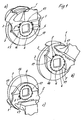
- Figur 1
- eine an einer Achse mittels einer erfindungsgemäßen Verbindung befestigte Bremse in unterschiedlichen Positionen angeordnet, jeweils in einer perspektivischen Darstellung
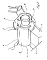
- Figur 2
- eine Einzelheit der Darstellung nach
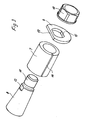
Figur 1 in einer teilweise geschnittenen perspektivischen Ansicht - Figur 3
- eine Explosivdarstellung der Einzelheit nach
Figur 2 - In der
Figur 1 ist eine Bremse 1 in Form einer Scheibenbremse dargestellt, die mit einem Achsanschluss 4 einer im übrigen nicht dargestellten Achse eines vorzugsweise Nutzfahrzeuges verbunden ist. - Bei diesem Ausführungsbeispiel handelt es sich um eine Festsattelbremse, die mit einem Bremssattel 2 an dem Achsanschluss 4 befestigt ist.
- Hierzu sind Formschlussmittel 5 vorgesehen, die stiftartig ausgebildet sind und in axial sich erstreckenden Ausnehmungen 6 sowohl des Achsanschlusses 4 wie auch des Bremssattels 2 einliegen.
- Diese Ausnehmungen 6, die in gleichmäßigen Winkelabstand über den Umfang des kreisförmigen Achsanschlusses 4 und einen Teilumfang des daran angepassten Bremssattels verteilt sind, sind jeweils als Halbloch ausgebildet, so dass sie übereinander liegend gemeinsam ein Loch ergeben, in dem ein Formschlussmittel 5 einliegt.
- Entsprechend der Teilung der Ausnehmungen 6 kann die Bremse 1 in unterschiedlichen Winkelstellungen am Achsanschluss 4 befestigt werden. In dem in der
Figur 1 gezeigten Beispiel sind drei mit a), b) und c) bezeichnete Stellungen erkennbar. - Durch den Formschluss mittels der Formschlussmittel 5 werden die beim Abbremsen einer Bremsscheibe 3, die mit einem nicht dargestellten Rad fest verbunden ist, auf den Bremssattel 2 einwirkenden Bremskräfte auf den gegenüber der Bremsscheibe 3 starren Achsanschluss 4 übertragen.
- Zur axialen Sicherung der Bremse 1 gegenüber dem Achsanschluss 4 sind an einem Spannbügel 16 und/oder dem Bremssattel 2 Axialanschläge vorgesehen, an denen der Achsanschluss 4 anliegt.
- Durch die geschlitzte und kegelförmige Ausführung der Formschlussmittel 5 werden Bearbeitungstoleranzen der Bauteile selbst und der Bauteile zueinander ausgeglichen und so eine Optimierung des Traglastanteils erreicht. Des weiteren ist eine spielfreie Einstellung und Fixierung möglich.
- Zu diesem Zweck weist das Formschlussmittel 5 eine Spreizhülse 7 auf, die mit einer konischen Innenbohrung versehen ist und die mit ihrer Mantelfläche zumindest teilweise an den Leibungen der Ausnehmungen 6 anliegt.
- Zur Spreizung der Spreizhülse 7 ist darin ein Spannelement 8 in Form eines Kegelbolzens geführt, der in seiner Koniszität der Kegelbohrung der Spreizhülse 7 angepasst ist.
- An einem Ende ist das Spannelement 8 mit einem Gewindezapfen 11 versehen, auf den eine Mutter 10 aufgeschraubt ist, die sich im vorliegenden Ausführungsbeispiel mittelbar an einer Stirnseite der Spreizhülse 7 abstützt.
- Wie insbesondere die
Figur 3 sehr deutlich zeigt, ist die Spreizhülse 7 mit einem durchgehenden Längsschlitz 14 versehen, so dass beim Anziehen der Mutter 10 eine einwandfreie Spreizung der Spreizhülse 7 unter Anpressung an die Ausnehmungen 6 gewährleistet ist. - Zur Verdrehsicherung des Formschlussmittels 5 bei der Montage weist das Spannelement 8 auf seiner dem Gewindezapfen 11 zugewandten Seite des konischen Abschnitts zwei gegenüber liegende Abplattungen 12 auf, an denen Abflachungen 15 einer Sicherungsscheibe 9 anliegen, die wiederum verdrehsicher im Endbereich der Ausnehmungen 6 einerseits im Bremssattel 2 und andererseits im Achsanschluss 4 einliegt. Dabei ist die Sicherungsscheibe 9 zwischen der zugeordneten Stirnseite der Spreizhülse 7 und der Mutter 10 eingeklemmt.
- Zur Verdrehsicherung im Bremssattel 2 bzw. im Achsanschluss 4 weist die ringförmige Sicherungsscheibe 9 eine Sehnenfläche 13 auf, die mit entsprechenden Ausformungen des Bremssattels 2 und/oder des Achsanschlusses 4 korrespondiert.
- Selbstverständlich ist die erfindungsgemäße Verbindung nicht beschränkt auf den Einsatz einer Festsattelbremse, entsprechend dem dargestellten Ausführungsbeispiel, sondern durchaus auch einsetzbar bei einer Schwenk- oder Schiebesattelbremse, wobei im letzteren Fall ein Bremsträger mit dem Achsanschluss 4 verbunden ist.
-
- 1
- Bremse
- 2
- Bremssattel
- 3
- Bremsscheibe
- 4
- Achsanschluss
- 5
- Formschlussmittel
- 6
- Ausnehmung
- 7
- Spreizhülse
- 8
- Spannelement
- 9
- Sicherungsscheibe
- 10
- Mutter
- 11
- Gewindezapfen
- 12
- Abplattung
- 13
- Sehnenfläche
- 14
- Längsschlitz
- 15
- Abflachung
- 16
- Spannbügel
- 17
- Axialanschlag
Claims (15)
- Verbindung einer Bremse (1), insbesondere einer Scheibenbremse, mit einer Achse eines Fahrzeuges, vorzugsweise eines Nutzfahrzeuges, wobei ein Bremssteil der Bremse (1) in Form eines Bremsträgers oder Bremssattels (2) verdreh- und verschiebegesichert an einem starren Achsanschluss (4) der Achse befestigt ist, dadurch gekennzeichnet, dass zur Drehmomentenübertragung von der Bremse (1) auf die Achse das Bremsteil und der Achsanschluss (4) durch Formschlussmittel (5) miteinander verbunden sind, die jeweils in einander zugeordneten Ausnehmungen (6) des Achsanschlusses (4) und des Bremsteiles einliegen.
- Verbindung nach Anspruch 1, dadurch gekennzeichnet, dass die Ausnehmungen (6) in gleichem Winkelabstand über zumindest einen Teilbereich des Umfangs des kreisförmigen Achsanschlusses (4) und des daran angepassten Bremsteiles angeordnet sind.
- Verbindung nach einem der vorhergehenden Ansprüche, dadurch gekennzeichnet, dass die einander zugeordneten Ausnehmungen (6) des Achsanschlusses (4) und des Bremsteiles jeweils halblochartig ausgebildet sind.
- Verbindung nach einem der vorhergehenden Ansprüche, dadurch gekennzeichnet, dass sich die Ausnehmungen (6) axial erstrecken.
- Verbindung nach einem der vorhergehenden Ansprüche, dadurch gekennzeichnet, dass die Formschlussmittel (5) in axialer Richtung reibschlüssig im Bremsteil und im Achsanschluss (4) einliegen.
- Verbindung nach einem der vorhergehenden Ansprüche, dadurch gekennzeichnet, dass das Formschlussmittel (5) eine Spreizhülse (7) aufweist, deren Außenfläche zumindest teilweise an der Leibung der Ausnehmungen (6) des Bremsteiles und des Achsanschlusses (4) angepresst ist.
- Verbindung nach einem der vorhergehenden Ansprüche, dadurch gekennzeichnet, dass die Spreizhülse (7) eine konische Innenbohrung aufweist, in der ein bereichsweise als Kegelbolzen ausgebildete Spannelement (8) geführt ist, wobei die Koniszität des Kegelbolzens und der Innenbohrung der Spreizhülse (7) angepasst sind.
- Verbindung nach einem der vorhergehenden Ansprüche, dadurch gekennzeichnet, dass die Koniszität des Spannelementes (8) und der Innenbohrung der Spreizhülse (7) in ihrer Neigung so ausgebildet ist, dass das Spannelement (8) selbsthemmend in der Spreizhülse (7) einliegt.
- Verbindung nach einem der vorhergehenden Ansprüche, dadurch gekennzeichnet, dass sich an den konischen Teil des Spannelementes (8) ein Gewindezapfen (11) anschließt, auf den eine Mutter (10) aufgeschraubt ist, die sich mittelbar oder unmittelbar an der zugeordneten Stirnseite der Spreizhülse (7) abstützt.
- Verbindung nach einem der vorhergehenden Ansprüche, dadurch gekennzeichnet, dass die Spreizhülse (7) einen durchgehenden Längsschlitz (14) aufweist.
- Verbindung nach einem der vorhergehenden Ansprüche, dadurch gekennzeichnet, dass das Formschlussmittel (5) verdrehsicher in den Ausnehmungen (6) einliegt.
- Verbindung nach einem der vorhergehenden Ansprüche, dadurch gekennzeichnet, dass zur Verdrehsicherung zwischen der Spreizhülse (7) und der Mutter (10) eine Sicherungsscheibe (9) eingeklemmt ist, die verdrehsicher in dem Bremsteil und/oder dem Achsanschluss einliegt.
- Verbindung nach einem der vorhergehenden Ansprüche, dadurch gekennzeichnet, dass die ringförmige Sicherungsscheibe (9) außenseitig eine Sehnenfläche (13) aufweist, die mit einem angepassten Vorsprung des Bremsteiles oder des Achsanschlusses (4) korrespondiert.
- Verbindung nach einem der vorhergehenden Ansprüche, dadurch gekennzeichnet, dass die Sicherungsscheibe (9) verdrehsicher auf dem Spannelement (8) gehalten ist.
- Verbindung nach einem der vorhergehenden Ansprüche, dadurch gekennzeichnet, dass der dem Gewindezapfen (11) zugewandte konische Endbereich des Spannelementes (8) mit mindestens einer Abplattung (12) versehen ist, an der eine Abflachung (15) der Sicherungsscheibe (9) anliegt.
Applications Claiming Priority (2)
| Application Number | Priority Date | Filing Date | Title |
|---|---|---|---|
| DE102005003770A DE102005003770B3 (de) | 2005-01-27 | 2005-01-27 | Verbindung einer Bremse mit einer Achse eines Fahrzeuges |
| PCT/EP2006/000205 WO2006079450A1 (de) | 2005-01-27 | 2006-01-12 | Verbindung einer bremse mit einer achse eines fahrzeuges |
Publications (2)
| Publication Number | Publication Date |
|---|---|
| EP1844247A1 EP1844247A1 (de) | 2007-10-17 |
| EP1844247B1 true EP1844247B1 (de) | 2009-06-03 |
Family
ID=36221015
Family Applications (1)
| Application Number | Title | Priority Date | Filing Date |
|---|---|---|---|
| EP06706202A Expired - Lifetime EP1844247B1 (de) | 2005-01-27 | 2006-01-12 | Verbindung einer bremse mit einer achse eines fahrzeuges |
Country Status (4)
| Country | Link |
|---|---|
| EP (1) | EP1844247B1 (de) |
| AT (1) | ATE433060T1 (de) |
| DE (2) | DE102005003770B3 (de) |
| WO (1) | WO2006079450A1 (de) |
Cited By (1)
| Publication number | Priority date | Publication date | Assignee | Title |
|---|---|---|---|---|
| US9435391B2 (en) | 2012-07-13 | 2016-09-06 | Knorr-Bremse Systeme Fuer Nutzfahrzeuge Gmbh | Disc brake for a commercial vehicle |
Families Citing this family (5)
| Publication number | Priority date | Publication date | Assignee | Title |
|---|---|---|---|---|
| DE102007051154B4 (de) * | 2007-10-25 | 2016-03-31 | Knorr-Bremse Systeme für Nutzfahrzeuge GmbH | Verbindung einer Bremse mit einer Achse eines Fahrzeuges |
| DE102008047190B4 (de) * | 2008-09-15 | 2010-06-17 | Daimler Ag | Bremsscheibe |
| JP5649921B2 (ja) * | 2010-11-16 | 2015-01-07 | ポップリベット・ファスナー株式会社 | ブラインドリベット及びその締結方法 |
| DE102014113521A1 (de) * | 2014-09-19 | 2016-03-24 | Knorr-Bremse Systeme für Nutzfahrzeuge GmbH | Bremsträger einer Scheibenbremse und Anordnung eines Bremsträgers einer Scheibenbremse an einer Fahrzeugachse |
| DE102017116112A1 (de) * | 2017-07-18 | 2019-01-24 | Bpw Bergische Achsen Kg | Scheibenbremse mit darin angeordneter Zuspannvorrichtung sowie Stützrolle für die Zuspannvorrichtung |
Family Cites Families (7)
| Publication number | Priority date | Publication date | Assignee | Title |
|---|---|---|---|---|
| US2960358A (en) * | 1958-03-06 | 1960-11-15 | Lewis D Christison | Hub and bushing assembly |
| GB1194411A (en) * | 1967-02-14 | 1970-06-10 | Dennis Arthur Jeffs | Improved Shaft Bushing |
| DE2201885A1 (de) * | 1972-01-15 | 1973-08-16 | Porsche Kg | Bremsscheibe fuer scheibenbremsanlagen in kraftfahrzeugen |
| DE3721692A1 (de) * | 1987-07-01 | 1989-01-12 | Lenze Gmbh & Co Kg Extertal | Verfahren zum herstellen einer riemenscheibe fuer ein verstellgetriebe und riemenscheibe |
| DE20009845U1 (de) * | 2000-05-31 | 2000-10-05 | Ateliers Mosellans de Construction de Réducteurs S.à.r.l., Forbach | Kopplungsvorrichtung |
| DE50111500D1 (de) * | 2000-08-17 | 2007-01-04 | Knorr Bremse Systeme | Scheibenbremse mit einer nachstell-einrichtung auf jeder seite der bremsscheibe |
| DE10202778B4 (de) * | 2002-01-25 | 2018-05-30 | Bpw Bergische Achsen Kg | Bremsträgeranordnung |
-
2005
- 2005-01-27 DE DE102005003770A patent/DE102005003770B3/de not_active Expired - Fee Related
-
2006
- 2006-01-12 DE DE502006003880T patent/DE502006003880D1/de not_active Expired - Lifetime
- 2006-01-12 AT AT06706202T patent/ATE433060T1/de not_active IP Right Cessation
- 2006-01-12 EP EP06706202A patent/EP1844247B1/de not_active Expired - Lifetime
- 2006-01-12 WO PCT/EP2006/000205 patent/WO2006079450A1/de not_active Ceased
Cited By (1)
| Publication number | Priority date | Publication date | Assignee | Title |
|---|---|---|---|---|
| US9435391B2 (en) | 2012-07-13 | 2016-09-06 | Knorr-Bremse Systeme Fuer Nutzfahrzeuge Gmbh | Disc brake for a commercial vehicle |
Also Published As
| Publication number | Publication date |
|---|---|
| DE502006003880D1 (de) | 2009-07-16 |
| ATE433060T1 (de) | 2009-06-15 |
| DE102005003770B3 (de) | 2006-07-06 |
| WO2006079450A1 (de) | 2006-08-03 |
| EP1844247A1 (de) | 2007-10-17 |
Similar Documents
| Publication | Publication Date | Title |
|---|---|---|
| EP2304263B1 (de) | Wellenbremsscheibe, insbesondere für ein schienenfahrzeug | |
| EP3135948B1 (de) | Vorrichtung zur befestigung eines verschleisssensors an einem bremshebel einer fahrzeugbremse | |
| EP3099956B1 (de) | Scheibenbremse umfassend eine schwingungsdämpfungseinrichtung mit einer zusatzmasse und bausatz mit einer derartigen scheibenbremse | |
| EP2690304B1 (de) | Zuspanneinrichtung einer Scheibenbremse für ein Nutzfahrzeug | |
| EP0928249A1 (de) | Spielfreie radbefestigung | |
| EP1844247B1 (de) | Verbindung einer bremse mit einer achse eines fahrzeuges | |
| EP1565668B1 (de) | Schreibenbremse mit einer nachstelleinrichtung, insbesondere für ein nutzfahrzeug | |
| EP1960753B1 (de) | Haltevorrichtung für eine felge eines fahrzeugrades | |
| DE19945255A1 (de) | Radlagerung, insbesondere für nichtangetriebene Fahrzeugachsen | |
| DE102023205264A1 (de) | Bremssattel für eine elektromechanische Bremse | |
| EP3779229B1 (de) | Kupplungsring | |
| DE102005059247B4 (de) | Bremsvorrichtung | |
| WO1994018470A1 (de) | Befestigungsvorrichtung für scheibenbremsen | |
| EP3478984A1 (de) | Achsenend-baugruppe mit einer radnabeneinheit und einer radbremse | |
| EP2236369B1 (de) | Verbindung einer Bremse mit einer Radachse eines Kraftfahrzeugs | |
| DE19858243B4 (de) | Bremsscheibe für Scheibenbremsen | |
| EP4038291B1 (de) | Bremsstempel einer scheibenbremse eines nutzfahrzeugs und scheibenbremse | |
| EP1893881B1 (de) | Bremsvorrichtung | |
| EP1673548A1 (de) | An einer radnabe befestigbare bremsscheibe | |
| DE10206334C1 (de) | Kupplungsanordnung zum lösbaren Verbinden eines durch einen Hydromotor antreibbaren Rades eines Fahrzeugs mit der Abtriebswelle des Hydromotors | |
| DE102018107888B4 (de) | Nachstelleinrichtung einer Scheibenbremse | |
| DE102007051154B4 (de) | Verbindung einer Bremse mit einer Achse eines Fahrzeuges | |
| DE29616818U1 (de) | Spielfreie Radbefestigung | |
| DE102007036934A1 (de) | Schließring für eine Einrichtung zum Blockieren einer Lenkanlage eines Kraftwagens | |
| EP3234393A1 (de) | Deckellose kupplung mit hohlbolzen und zentrierhilfen |
Legal Events
| Date | Code | Title | Description |
|---|---|---|---|
| PUAI | Public reference made under article 153(3) epc to a published international application that has entered the european phase |
Free format text: ORIGINAL CODE: 0009012 |
|
| 17P | Request for examination filed |
Effective date: 20070827 |
|
| AK | Designated contracting states |
Kind code of ref document: A1 Designated state(s): AT BE BG CH CY CZ DE DK EE ES FI FR GB GR HU IE IS IT LI LT LU LV MC NL PL PT RO SE SI SK TR |
|
| DAX | Request for extension of the european patent (deleted) | ||
| 17Q | First examination report despatched |
Effective date: 20080704 |
|
| GRAP | Despatch of communication of intention to grant a patent |
Free format text: ORIGINAL CODE: EPIDOSNIGR1 |
|
| GRAS | Grant fee paid |
Free format text: ORIGINAL CODE: EPIDOSNIGR3 |
|
| GRAA | (expected) grant |
Free format text: ORIGINAL CODE: 0009210 |
|
| AK | Designated contracting states |
Kind code of ref document: B1 Designated state(s): AT BE BG CH CY CZ DE DK EE ES FI FR GB GR HU IE IS IT LI LT LU LV MC NL PL PT RO SE SI SK TR |
|
| REG | Reference to a national code |
Ref country code: GB Ref legal event code: FG4D Free format text: NOT ENGLISH |
|
| REG | Reference to a national code |
Ref country code: CH Ref legal event code: EP |
|
| REG | Reference to a national code |
Ref country code: IE Ref legal event code: FG4D Free format text: LANGUAGE OF EP DOCUMENT: GERMAN |
|
| REF | Corresponds to: |
Ref document number: 502006003880 Country of ref document: DE Date of ref document: 20090716 Kind code of ref document: P |
|
| PG25 | Lapsed in a contracting state [announced via postgrant information from national office to epo] |
Ref country code: FI Free format text: LAPSE BECAUSE OF FAILURE TO SUBMIT A TRANSLATION OF THE DESCRIPTION OR TO PAY THE FEE WITHIN THE PRESCRIBED TIME-LIMIT Effective date: 20090603 Ref country code: LT Free format text: LAPSE BECAUSE OF FAILURE TO SUBMIT A TRANSLATION OF THE DESCRIPTION OR TO PAY THE FEE WITHIN THE PRESCRIBED TIME-LIMIT Effective date: 20090603 |
|
| NLV1 | Nl: lapsed or annulled due to failure to fulfill the requirements of art. 29p and 29m of the patents act | ||
| PG25 | Lapsed in a contracting state [announced via postgrant information from national office to epo] |
Ref country code: NL Free format text: LAPSE BECAUSE OF FAILURE TO SUBMIT A TRANSLATION OF THE DESCRIPTION OR TO PAY THE FEE WITHIN THE PRESCRIBED TIME-LIMIT Effective date: 20090603 Ref country code: SI Free format text: LAPSE BECAUSE OF FAILURE TO SUBMIT A TRANSLATION OF THE DESCRIPTION OR TO PAY THE FEE WITHIN THE PRESCRIBED TIME-LIMIT Effective date: 20090603 Ref country code: LV Free format text: LAPSE BECAUSE OF FAILURE TO SUBMIT A TRANSLATION OF THE DESCRIPTION OR TO PAY THE FEE WITHIN THE PRESCRIBED TIME-LIMIT Effective date: 20090603 Ref country code: PL Free format text: LAPSE BECAUSE OF FAILURE TO SUBMIT A TRANSLATION OF THE DESCRIPTION OR TO PAY THE FEE WITHIN THE PRESCRIBED TIME-LIMIT Effective date: 20090603 Ref country code: SE Free format text: LAPSE BECAUSE OF FAILURE TO SUBMIT A TRANSLATION OF THE DESCRIPTION OR TO PAY THE FEE WITHIN THE PRESCRIBED TIME-LIMIT Effective date: 20090903 |
|
| REG | Reference to a national code |
Ref country code: IE Ref legal event code: FD4D |
|
| PG25 | Lapsed in a contracting state [announced via postgrant information from national office to epo] |
Ref country code: CZ Free format text: LAPSE BECAUSE OF FAILURE TO SUBMIT A TRANSLATION OF THE DESCRIPTION OR TO PAY THE FEE WITHIN THE PRESCRIBED TIME-LIMIT Effective date: 20090603 Ref country code: EE Free format text: LAPSE BECAUSE OF FAILURE TO SUBMIT A TRANSLATION OF THE DESCRIPTION OR TO PAY THE FEE WITHIN THE PRESCRIBED TIME-LIMIT Effective date: 20090603 Ref country code: RO Free format text: LAPSE BECAUSE OF FAILURE TO SUBMIT A TRANSLATION OF THE DESCRIPTION OR TO PAY THE FEE WITHIN THE PRESCRIBED TIME-LIMIT Effective date: 20090603 Ref country code: ES Free format text: LAPSE BECAUSE OF FAILURE TO SUBMIT A TRANSLATION OF THE DESCRIPTION OR TO PAY THE FEE WITHIN THE PRESCRIBED TIME-LIMIT Effective date: 20090914 Ref country code: IE Free format text: LAPSE BECAUSE OF FAILURE TO SUBMIT A TRANSLATION OF THE DESCRIPTION OR TO PAY THE FEE WITHIN THE PRESCRIBED TIME-LIMIT Effective date: 20090603 Ref country code: IS Free format text: LAPSE BECAUSE OF FAILURE TO SUBMIT A TRANSLATION OF THE DESCRIPTION OR TO PAY THE FEE WITHIN THE PRESCRIBED TIME-LIMIT Effective date: 20091003 |
|
| PG25 | Lapsed in a contracting state [announced via postgrant information from national office to epo] |
Ref country code: SK Free format text: LAPSE BECAUSE OF FAILURE TO SUBMIT A TRANSLATION OF THE DESCRIPTION OR TO PAY THE FEE WITHIN THE PRESCRIBED TIME-LIMIT Effective date: 20090603 |
|
| PG25 | Lapsed in a contracting state [announced via postgrant information from national office to epo] |
Ref country code: BG Free format text: LAPSE BECAUSE OF FAILURE TO SUBMIT A TRANSLATION OF THE DESCRIPTION OR TO PAY THE FEE WITHIN THE PRESCRIBED TIME-LIMIT Effective date: 20090903 Ref country code: PT Free format text: LAPSE BECAUSE OF FAILURE TO SUBMIT A TRANSLATION OF THE DESCRIPTION OR TO PAY THE FEE WITHIN THE PRESCRIBED TIME-LIMIT Effective date: 20091003 |
|
| PLBE | No opposition filed within time limit |
Free format text: ORIGINAL CODE: 0009261 |
|
| STAA | Information on the status of an ep patent application or granted ep patent |
Free format text: STATUS: NO OPPOSITION FILED WITHIN TIME LIMIT |
|
| PG25 | Lapsed in a contracting state [announced via postgrant information from national office to epo] |
Ref country code: DK Free format text: LAPSE BECAUSE OF FAILURE TO SUBMIT A TRANSLATION OF THE DESCRIPTION OR TO PAY THE FEE WITHIN THE PRESCRIBED TIME-LIMIT Effective date: 20090603 |
|
| 26N | No opposition filed |
Effective date: 20100304 |
|
| BERE | Be: lapsed |
Owner name: KNORR-BREMSE SYSTEME FUR NUTZFAHRZEUGE G.M.B.H. Effective date: 20100131 |
|
| PG25 | Lapsed in a contracting state [announced via postgrant information from national office to epo] |
Ref country code: MC Free format text: LAPSE BECAUSE OF NON-PAYMENT OF DUE FEES Effective date: 20100131 |
|
| REG | Reference to a national code |
Ref country code: CH Ref legal event code: PL |
|
| GBPC | Gb: european patent ceased through non-payment of renewal fee |
Effective date: 20100112 |
|
| REG | Reference to a national code |
Ref country code: FR Ref legal event code: ST Effective date: 20100930 |
|
| PG25 | Lapsed in a contracting state [announced via postgrant information from national office to epo] |
Ref country code: FR Free format text: LAPSE BECAUSE OF NON-PAYMENT OF DUE FEES Effective date: 20100201 Ref country code: CH Free format text: LAPSE BECAUSE OF NON-PAYMENT OF DUE FEES Effective date: 20100131 Ref country code: LI Free format text: LAPSE BECAUSE OF NON-PAYMENT OF DUE FEES Effective date: 20100131 Ref country code: GR Free format text: LAPSE BECAUSE OF FAILURE TO SUBMIT A TRANSLATION OF THE DESCRIPTION OR TO PAY THE FEE WITHIN THE PRESCRIBED TIME-LIMIT Effective date: 20090904 |
|
| PG25 | Lapsed in a contracting state [announced via postgrant information from national office to epo] |
Ref country code: GB Free format text: LAPSE BECAUSE OF NON-PAYMENT OF DUE FEES Effective date: 20100112 |
|
| PG25 | Lapsed in a contracting state [announced via postgrant information from national office to epo] |
Ref country code: BE Free format text: LAPSE BECAUSE OF NON-PAYMENT OF DUE FEES Effective date: 20100131 |
|
| PG25 | Lapsed in a contracting state [announced via postgrant information from national office to epo] |
Ref country code: IT Free format text: LAPSE BECAUSE OF FAILURE TO SUBMIT A TRANSLATION OF THE DESCRIPTION OR TO PAY THE FEE WITHIN THE PRESCRIBED TIME-LIMIT Effective date: 20090603 |
|
| REG | Reference to a national code |
Ref country code: AT Ref legal event code: MM01 Ref document number: 433060 Country of ref document: AT Kind code of ref document: T Effective date: 20110112 |
|
| PG25 | Lapsed in a contracting state [announced via postgrant information from national office to epo] |
Ref country code: CY Free format text: LAPSE BECAUSE OF FAILURE TO SUBMIT A TRANSLATION OF THE DESCRIPTION OR TO PAY THE FEE WITHIN THE PRESCRIBED TIME-LIMIT Effective date: 20090603 |
|
| PG25 | Lapsed in a contracting state [announced via postgrant information from national office to epo] |
Ref country code: LU Free format text: LAPSE BECAUSE OF NON-PAYMENT OF DUE FEES Effective date: 20100112 Ref country code: HU Free format text: LAPSE BECAUSE OF FAILURE TO SUBMIT A TRANSLATION OF THE DESCRIPTION OR TO PAY THE FEE WITHIN THE PRESCRIBED TIME-LIMIT Effective date: 20091204 |
|
| PG25 | Lapsed in a contracting state [announced via postgrant information from national office to epo] |
Ref country code: TR Free format text: LAPSE BECAUSE OF FAILURE TO SUBMIT A TRANSLATION OF THE DESCRIPTION OR TO PAY THE FEE WITHIN THE PRESCRIBED TIME-LIMIT Effective date: 20090603 |
|
| PG25 | Lapsed in a contracting state [announced via postgrant information from national office to epo] |
Ref country code: AT Free format text: LAPSE BECAUSE OF NON-PAYMENT OF DUE FEES Effective date: 20110112 |
|
| PGFP | Annual fee paid to national office [announced via postgrant information from national office to epo] |
Ref country code: DE Payment date: 20190124 Year of fee payment: 14 |
|
| REG | Reference to a national code |
Ref country code: DE Ref legal event code: R119 Ref document number: 502006003880 Country of ref document: DE |
|
| PG25 | Lapsed in a contracting state [announced via postgrant information from national office to epo] |
Ref country code: DE Free format text: LAPSE BECAUSE OF NON-PAYMENT OF DUE FEES Effective date: 20200801 |