EP1844438B1 - Verfahren und system zur simulation oder digitalen synthese echographischer bilder - Google Patents
Verfahren und system zur simulation oder digitalen synthese echographischer bilder Download PDFInfo
- Publication number
- EP1844438B1 EP1844438B1 EP06709150A EP06709150A EP1844438B1 EP 1844438 B1 EP1844438 B1 EP 1844438B1 EP 06709150 A EP06709150 A EP 06709150A EP 06709150 A EP06709150 A EP 06709150A EP 1844438 B1 EP1844438 B1 EP 1844438B1
- Authority
- EP
- European Patent Office
- Prior art keywords
- image
- simulation
- sonographic
- probe
- effects
- Prior art date
- Legal status (The legal status is an assumption and is not a legal conclusion. Google has not performed a legal analysis and makes no representation as to the accuracy of the status listed.)
- Expired - Lifetime
Links
Images


Classifications
-
- G—PHYSICS
- G09—EDUCATION; CRYPTOGRAPHY; DISPLAY; ADVERTISING; SEALS
- G09B—EDUCATIONAL OR DEMONSTRATION APPLIANCES; APPLIANCES FOR TEACHING, OR COMMUNICATING WITH, THE BLIND, DEAF OR MUTE; MODELS; PLANETARIA; GLOBES; MAPS; DIAGRAMS
- G09B23/00—Models for scientific, medical, or mathematical purposes, e.g. full-sized devices for demonstration purposes
- G09B23/28—Models for scientific, medical, or mathematical purposes, e.g. full-sized devices for demonstration purposes for medicine
- G09B23/286—Models for scientific, medical, or mathematical purposes, e.g. full-sized devices for demonstration purposes for medicine for scanning or photography techniques, e.g. X-rays, ultrasonics
-
- G—PHYSICS
- G06—COMPUTING OR CALCULATING; COUNTING
- G06T—IMAGE DATA PROCESSING OR GENERATION, IN GENERAL
- G06T5/00—Image enhancement or restoration
- G06T5/50—Image enhancement or restoration using two or more images, e.g. averaging or subtraction
-
- G—PHYSICS
- G06—COMPUTING OR CALCULATING; COUNTING
- G06T—IMAGE DATA PROCESSING OR GENERATION, IN GENERAL
- G06T2207/00—Indexing scheme for image analysis or image enhancement
- G06T2207/10—Image acquisition modality
- G06T2207/10072—Tomographic images
- G06T2207/10088—Magnetic resonance imaging [MRI]
-
- G—PHYSICS
- G06—COMPUTING OR CALCULATING; COUNTING
- G06T—IMAGE DATA PROCESSING OR GENERATION, IN GENERAL
- G06T2207/00—Indexing scheme for image analysis or image enhancement
- G06T2207/20—Special algorithmic details
- G06T2207/20212—Image combination
- G06T2207/20221—Image fusion; Image merging
Definitions
- the present invention relates to the field of imaging and exploration techniques, particularly in the medical field and more particularly in the context of the simulation or synthesis of virtual images, and relates to a method and a simulation system or digital synthesis of ultrasound images, planar or not.
- Ultrasound whose technique and characteristics are well known to those skilled in the art, has many advantages over other imaging techniques: it is not harmful in high doses such as radiography and CT, the cost of the apparatus and that of the examinations is lower, and the size of the ultrasound scanners is small.
- an ultrasound the area involved in the pathology of the patient is performed.
- the rapid acquisition of images gives it a very interesting dynamic character for observation or guidance.
- the principle of the invention is based on the direct transformation of NMR (or NMR) nuclear magnetic resonance images, hereinafter also called Magnetic Resonance Imaging (or MRI), in ultrasound images. In order to understand the invention, it is therefore necessary to briefly describe the principles of these different images.
- Magnetic Resonance Imaging is a diagnostic technique that provides anatomically accurate sectional images without the use of X-rays or other radiation.
- MRI is based on the physical phenomenon of nuclear magnetic resonance (NMR). It uses the properties of matter and only concerns the hydrogen nuclei, very abundant in the human body.
- NMR nuclear magnetic resonance
- a hollow cylindrical magnet provides an intense magnetic field (typically 1 to 3 Tesla) about 60,000 times greater than the Earth's magnetic field. This magnetic field gives rise to magnetization in the various tissues of the body, which is due to the hydrogen nuclei, as if each nucleus behaved like a small compass.
- the magnetic resonance phenomenon makes it possible to measure this magnetization. For this, the hydrogen nuclei are disturbed by emitting an electromagnetic wave towards the patient.
- the hydrogen nuclei tilt their magnetization with respect to the direction of the magnetic field.
- the magnetization returns to its position of equilibrium: it is the return of the magnetization to this state of equilibrium which is measured.
- the images obtained will be very different depending on the settings of the chosen device and the type of information sought.
- the main images will thus depend on the weighting that can be of type T1 (calculation of the relaxation along the longitudinal axis of the magnetization), or T2 (calculation of the relaxation along the transversal axis of the magnetization), in density of protons, in FLAIR mode (FLuid Attenuation Inversion Reconvery), in T2 *, each of these images being able to be realized in echo mode of Spin or echo of gradient.
- Ultrasound is a medical imaging technique that uses ultrasound to get an image of the inside of the body.
- the ultrasound probe sends ultrasound that returns to the probe, after having reflected on the organ that one wants to study, in order to be treated by a computer.
- the ultrasound image is therefore a reflection image.
- the reflection of the ultrasonic beam is done on interfaces constituted by tissues having different acoustic impedances and also to a lesser extent on the irregularities of these tissues due to the dispersion.
- Ultrasonic pulses obey the same laws of propagation, reflection and refraction as those of optics.
- the ultrasound beam is attenuated according to the nature of the organs through which it passes.
- the determining parameters in the propagation of sounds in different media are the density or density (d) and the speed of sound propagation (v).
- the table below shows the acoustic impedances for different media present in every human or animal body.
- the four physical phenomena that come into play in the behavior of an ultrasonic wave are: reflection, refraction, attenuation, and dispersion.
- An echo is a sound (sound wave) which is reflected and which is received after a latency, corresponding to its time of movement in the medium concerned.
- a portion of the beam is reflected with a reflection angle equal to the incident angle. This is the phenomenon of reflection.
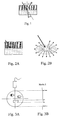
- the transmitted part is deflected with an angle that depends on the speed of propagation of the two media concerned. This is the phenomenon of refraction (see figure 1 attached).
- the proportion of reflected ultrasound, or reflection coefficient is directly related to the difference in acoustic impedance between the two media. This size is characteristic of the nature of the environment.
- the combination of the reflection and the refraction of the wave can induce multiple rebounds between the probe and the interface creating behind the interface ghost echoes called "echoes of repetition", the echoes being trapped between two reflecting interfaces before returning to the ultrasound probe.
- Attenuation is the loss of intensity of the ultrasound signal as a function of the depth of penetration of the tissues and their compositions.
- the system will automatically compensate for this decrease by amplifying the received signal so as to cancel the attenuation that the ultrasonic wave would have suffered if it had only passed through soft tissues.
- the tissues crossed by the ultrasound beam do not have soft tissue attenuation characteristics, there is either a reinforcement (this is the case for a liquid, which will have less attenuating power than that of soft tissues), or the appearance of shadows (this is the case for bone or gas, which will have an attenuating power greater than that of soft tissues).
- heterogeneous media are represented by scattering echoes.
- the echogenicity (the faculty of generating echoes) of the parenchymal organs, for example, is essentially formed by scattering echoes, the intensity of which depends on the tissue homogeneity (see Figures 2A and 2B appended).
- the invention essentially consists in reproducing by simulation an ultrasound image reproducing all the effects of attenuation, reflection, refraction and dispersion.
- the invention consists in reproducing two-dimensional images (representing one or more ultrasound planes) by simulating several ultrasonic beams emitted from a virtual probe that can be controlled in position and orientation and positioned in the volume of the MRI medical image.
- the important reflection phenomena of the wave will be observed at the interfaces between the liquids or the soft tissues on the one hand and the air or the bones on the other hand.
- the most important normal incidence reflection coefficients are observed between structures whose gray levels can be sufficiently far away in an MRI image according to the chosen acquisition sequence. Any MRI image can not therefore meet this criterion, and only the MRI images to differentiate the different structures that we seek to observe will then be transformed into ultrasound images.
- the large variations in the gray level between these different structures can be easily calculated in real time along the ray launched in such an MRI image.
- This gradient can then be translated into a reflection whose order of magnitude can either be parameterized interactively or be calculated automatically.
- the main advantage of this method implemented by the invention thus lies in the fact that it is not necessary to perform an initial segmentation of the organs to create an ultrasound image from an MRI image without pre-processing and in real time. which represents one of the main advantages of the invention.
- the subject of the invention is a process for the simulation or digital synthesis of ultrasound images, characterized by the direct, real-time, or near-real-time, transformation of the information contained in a medical or veterinary image of the MRI type, without delimitation. or segmentation of the organs or structures contained in the data volume of the MRI image, according to one or more two-dimensional observation windows that can be modified in real time, or near real time, in dimension, in position, in direction and in orientation, of which the characteristics are a function of the type of a determined virtual ultrasound probe, and reproducing all the effects of attenuation, reflection, refraction and dispersion and the adjustment effects of a real ultrasound image, each ultrasound image supplied cumulative the results of simulations of the aforementioned effects.
- the method advantageously performs the simulation of two-dimensional ultrasound images whose observation window is obtained by the simulation of several ultrasonic beams, oriented in parallel between them in the manner of a linear probe or oriented in different divergent directions in the manner of a sector probe, corresponding to a set of line segments originating from a virtual source characterizing the shape, direction, orientation and the dimension of the virtual probe and whose modifiable length makes it possible to simulate the frequency of the ultrasound by determining the maximum depth of exploration.
- a plane section with acquisition of the data contained in the portion of plane defined by the above-mentioned line segments, or by averaging data located on either side of said plan portion (in the absence of data on said plan portion), so as to obtain a two-dimensional data matrix extracted from said 3D MRI image.
- the method performs the simulation of three-dimensional ultrasound images defined by several two-dimensional observation windows simulated and oriented with differential offsets with respect to the position and the orientation of the virtual probe, or about its axis, each window then being characterized by a different angle around the median axis of this probe, or at the end of this probe, each window then being characterized by a different angle around the axis perpendicular to the observation plane of this probe.
- the method preferably consists in creating one or more window (s) or analysis space (s) for simulating two-dimensional or three-dimensional ultrasound images, window (s) or space (s) defined by the plane or volume in which a virtual sound wave simulated by a set of line segments originating at the virtual ultrasound probe, and ultimately representing a rectangle, a partial disk, a tube or a sphere portion centered on the origin of the probe, this volume varying according to the degree of precision of the final simulation of the ultrasound image.
- the method advantageously comprises the simulation of the ultrasound dispersion effects by the traversed structures present in a real ultrasound image, this simulation resulting in the creation of an absorption image limited to the observation window defined above, obtained by transforming the intensity levels n contained in the MRI image limited to the window or analysis space also defined previously, in grayscale I (n) of an ultrasound image, by the definition and application of a transfer function I simulating the orders of magnitude of the acoustic impedance values of the traversed structures, said function I being able to be continuous or not, linear or not depending on the modality, the type and the characteristics of the initial MRI image.
- the method advantageously comprises the simulation of the effects of reflection, refraction and attenuation of ultrasound by the traversed interfaces present in a real ultrasound image, this simulation resulting in the creation, on the one hand, of an image of attenuation simulating the effects of ultrasound shadows and the effects of sonographic reinforcements visible respectively beyond an interface between a soft tissue or a fluid and air or bone, and beyond an interface between a fluid and a soft tissue, and, on the other hand, a multiple echo image or mask, simulating the reverberation effects of an ultrasound echo inside a visible bone beyond an interface between a soft tissue or a liquid and bone, these images being both limited to the observation window defined above, and obtained along the paths of the directed ray throws (defining the window or windows ( s) or analysis area (s) by the real-time detection of the interfaces calculated by thresholding, gradient and / or filtering techniques of the initial MRI image densities limited to the window or analysis space defined according to claim 4.
- the method advantageously comprises the simulation of the dispersion noises experienced by the ultrasound in the tissues traversed or their effects.
- This simulation results in the creation of an image limited to the observation window defined above, simulating the effects of refraction and dispersion in an ultrasound image, obtained by calculating the effects of refraction and dispersion of the tissues traversed by the simulated ultrasound wave described above, this simulation being carried out either by defining a general noise in the image, or by more specifically simulating the aforementioned effects by detecting and characterizing the interfaces between the different structures of the scanned analysis window.
- the method advantageously comprises the simulation of the effects of the setting of the virtual or simulated ultrasound probe, resulting in the creation of an image or mask of limited adjustment (e) to the - 11 - observation window defined above and simulating the brightness, contrast, gain or any other adjustable parameter settings of the virtual or simulated ultrasound probe as previously defined.
- the method according to the invention realizes the creation of an ultrasound image limited to the observation window defined above, and combining the results of the four different simulations described above.
- the principle underlying the present invention is, for making ultrasound images of synthesis, to use directly three-dimensional MRI images, preferably of high precision, without performing a heavy pretreatment phase and significant consumer of time and processing power.
- ultrasound propagation can be modeled as a one-dimensional phenomenon.
- a first step of the method consists in performing a volumetric ray tracing directly in the three-dimensional MRI image in order to collect all the voxels lying in the investigation plane of the simulated virtual probe.
- Each possible propagation direction for the ultrasonic wave corresponds to a line of the resulting two-dimensional image.
- This image is then analyzed in order to extract at least two different information.
- the acoustic behavior of each pixel is estimated and, on the other hand, the interfaces cut or traversed by the rays (directions of propagation) are detected, identified and marked (soft tissue, bone, gas, liquid,. ..).
- At least three different simulations are performed, namely, a simulation of the ultrasound reflection effects by the traversed interfaces (reverberation), a simulation of the absorption effects of ultrasound by the traversed structures (attenuation) and a simulation of the dispersion effects and a noise matrix, associated with a simulation of the virtual probe settings.
- the first simulation provides a so-called “multiple echoes” image, created by exploiting the knowledge of the nature and position of the interfaces between organs or regions of different tissues. Thanks to this image, multiple echoes are detected and represented.
- the second simulation provides an absorption image that represents the accumulation of the absorption characteristics of materials and substances along the ultrasonic wave.
- the third simulation provides the background image or background texture, which is generated by combining, for each pixel, the value read in the MRI image and the information relating to the nature of the tissues concerned and its acoustic characteristics.
- the background image is further blurred by using randomly generated noise.
- the final simulated ultrasound image is the result of the fusion or combination of the above three images at least, limited to an observation window determined by the nature and the setting of the simulated probe, said resultant image being furthermore applied in a texture before it is displayed.
- This realization is based on a T2-type obstetric MRI image.
- the goal is to simulate an antenatal ultrasound and the algorithms described here have been optimized to improve the rendering of structures specific to the fetus. For the simulation of another type of examination or the same examination based on another type of MRI image, these algorithms may therefore be substantially different.
- the first module 1 of the algorithm consists in simulating the ultrasound probe, that is to say to define its static properties (2D or 3D probe, linear or sector probe) and its variable properties (position, direction, orientation, frequency of the emitted wave, gain, contrast, etc .).
- the implementation of this first module 1 is necessary for the realization of the invention which consists in creating a virtual ultrasound image from a virtual or simulated probe.
- the second module 2 (comprising four sub-modules 3, 3 ', 3 ", 3"'), which more particularly characterizes the invention, consists in creating the ultrasound image that would be generated by an actual ultrasound probe, the parameters of which are provided. by the first module 1, if it was frequency-tuned, localized, directed, oriented and parameterized according to the information provided by the first module, on a real subject of which part of the anatomical characteristics are provided by the MRI image.
- the ultrasound simulation module 2 is composed, as shown in FIG. figure 6 annexed, four main sub-modules 3, 3 ', 3 ", 3"' respectively performing dispersion, reflection, refraction and absorption (attenuation), noises due to refraction and dispersion and effects due to the setting of the probe, such as gain or contrast, for example.
- the first step of the simulation is to define the restricted space in which the simulated image will be recreated, as well as the analysis space to recreate the effects of absorption, reflection and noise. of refraction and dispersion in this image.
- the space of the image will correspond to a plane limited in its dimensions by the size of the probe and the frequency of the transmitted signal. If it is a linear probe, the shape of this space will be a rectangle whose width will be equal to the width of the probe and the length will depend on the frequency, whereas in the case of a sector probe, the shape of this space will be a disk section whose radius will depend on the frequency.
- the image space will in fact consist of several 2D spaces of sectoral or linear type.
- the analysis space corresponds for its part to the simulation of the propagation space and return to the probe of ultrasonic waves. he may vary depending on a compromise between realism and speed that can be defined by the user.
- On a weak computer for example, it will be possible to maintain an analysis space equal to the space of the image, but in this case, the tissues located outside the space of the ultrasound image will not be able to influence the image, as can be the case in the case of refraction in particular. If the computer is more powerful, widening the analysis space will improve the simulation while maintaining a real-time image generation. In absolute terms, it is unnecessary to keep the information beyond the maximum distance defined by the frequency of the waves emitted by the probe.
- the shape of the space thus generated will again depend on the type of probe used and will lead to either a sphere portion (linear or sectoral 2D or 3D probe), or to a complete cylinder (endoluminal ultrasound probe).
- the first submodule 3 consists in simulating the phenomenon of dispersion of the tissues traversed by the ultrasonic waves.
- the principle of the invention consists, in this regard, in simulating this phenomenon by transforming each level of gray or intensity of the MRI image into a gray level in the ultrasound image.
- a transfer function that converts a gray level or intensity n in the MRI image in an ultrasound intensity I (n) in the ultrasound image.
- This function may vary according to the characteristics of the MRI acquisition, depending on the nature of the organs on which the simulation will focus and / or according to the desired level of realism. It could for example be algebraic or correspond to a simple table of values.
- I echography (d) coef * d.
- any function will cause errors on certain values, since any transfer function can only attempt to simulate the real effect of the dispersion without ever being able to equal it since, physically, the gray levels or intensity of a MRI image and absorption of ultrasonic waves remain two physically uncorrelated phenomena. Whatever the level of precision of the transfer function, the approximations it entails may in any case be reduced by the other effects of reflection, refraction or absorption.
- the final result of this first sub-module 3 is the definition of a first image, corresponding to an echographic viewing window in gray levels without effect.
- the second sub-module 3 aims to simulate the phenomena of reflection, refraction and attenuation of the interfaces defining the effects related to these reflections, that is to say shadows and multiple echoes.
- the principle of the invention consists, in this regard, in simulating these oriented and directed phenomena as a function of the parameters of the probe, that is to say, limited to the viewing window, then in calculating the reflections according to the variations grayscale or intensity of the MRI image.
- the definition of these interfaces can be done in several ways: either by calculating the gradient of the initial MRI image, or by calculating the gradient of the modified MRI image by a transfer function equal to or different from the transfer function. defined in the first sub-module, or by any other method that leads to a similar result.
- the shadow phenomenon will appear when the interface will be too large, that is to say when the difference in impartance of two neighboring tissues will be too great.
- Air and bone have very dark gray levels in an MRI image since they contain very little water and therefore very few protons, while soft tissues and water may have median and high values grayscale or intensity in an MRI image according to the chosen modality.
- the principle of the invention will therefore be to create along the radius a strong attenuation of the densities beyond a detected interface if the interface is composed of very low values in this type of MRI image (corresponding to the air or bone).
- the simulation of this shadow will lead to a image, called attenuation mask, limited to the viewing window and whose actual values will be between 0 and 1 in order to be able to multiply them by the value of the absorption window.
- the attenuation of the gray levels of the final image will therefore be obtained by multiplying the initial values by the attenuation value.
- Some small interfaces may also cause a shadow phenomenon when they are not perpendicular to the direction of the ray.
- This phenomenon named edge shadow, is very important in obstetric ultrasound and is especially visible in the skull of the fetus.
- the direction of the gradient of the image must be taken into account to determine the orientation of the interface. The more oblique this is, the more important the phenomenon will be.
- the attenuation mask is modified according to this result.
- Some interfaces may have different attenuation effects that are characterized by enhancement.
- Reinforcement is a phenomenon of increasing gray levels in the direction of ultrasound waves emitted through a liquid. It can easily result in a slight increase in density beyond a detected interface if the interface is composed of very high gray levels in an MRI image (value corresponding to liquids). To characterize this increase, the simulation of this reinforcement will consist in defining in the reflection mask values higher than 1. In ultrasound images, a reinforcement will also cause a shadow effect on both sides of the liquid region. To characterize these shadows, the simulation will consist in defining in the reflection mask values close to 0.
- Important interfaces may finally create an effect called multiple echo which corresponds to a replication of an interface in depth in the same axis of the rays having defined the interface between a soft tissue or water and a bone or a solid element.
- the principle of the invention will therefore consist in creating along the axis of each ray a replication of the interface beyond a detected interface if this interface is composed of gray levels or intensity close to 0 in the MRI image (corresponding to the bone).
- the simulation of this multiple echo will result in an image, called a multiple echo window, limited to the viewing window and whose values will display the replications of the interface by increasing the gray levels of the ultrasound image. It may therefore be a mask whose pixel value will be multiplied by the value of the gray levels of the absorption window, or else an image whose value of the gray levels will be added to the value of the pixels. gray levels of the absorption window.
- the purpose of the third submodule 3 is to simulate the phenomena of dispersion noise, the principle of the invention being, in this respect, to simulate these phenomena by defining an image that will make it possible to modify the value of the gray levels of the absorption window
- the simulation of these phenomena is undoubtedly the most complex since they are not taken into account by the reconstruction software of a real ultrasound image and are thus characterized as a noise. implemented by a compromise between the realism of the effect and the processing time to achieve it.
- the simplest method is to calculate a random noise that reproduces a texture comparable to the noise observed in the ultrasound images.
- Gaussian noise oriented in the normal rays launched from the virtual probe and provides real-time first approximation simple and fast such noise.
- the most complex method is to calculate the two effects independently, taking into account their characteristics.
- the result of the third sub-module 3 "will ultimately be an image or a mask for changing the intensities of the absorption image.
- the purpose of the fourth submodule 3 is to simulate the parameters for adjusting the image supplied by the ultrasound probe.
- the principle of the invention consists, in this respect, in simulating these adjustments, which generally correspond to contrast, brightness or even gain functions more or less complex, by a mask for changing the simulated ultrasound image.
- image adjustment mask an image, limited to the window of visualization and whose real values will be between 0 and n, in order to be able to multiply them by the value of the simulated ultrasound image.
- the principle of the invention consists in providing a simulated ultrasound image with each of the effects and settings of an actual ultrasound image.
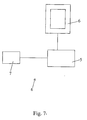
- a system 4 for simulation or digital synthesis of ultrasound images or real-time or quasi-real-time ultrasound simulator comprising at least one computer memory processing unit 5, a screen 6 of image display (s) and at least one means 7 for controlling and programming for a user.
- This simulator is characterized in that it implements the method for simulating or synthesizing digital images described above and in that said at least one control and programming means 7 is at least able to indicate to the user.
- treatment unit 5 the type of virtual ultrasound probe to be simulated, as well as, in real time or near real time, the various adjustment parameters and manipulation of this probe by the user, and possibly the medical or veterinary image of 3D MRI type selected by the user from several available images.
- said at least one control and programming means 7 comprises a force or force feedback interface making it possible to simulate the positioning characteristics of the probe relative to the virtual subject.
- a force or force feedback interface making it possible to simulate the positioning characteristics of the probe relative to the virtual subject.
- the method according to the invention can be applied as much for the simulation of two-dimensional ultrasound images, as three-dimensional (reconstructed from two-dimensional images).
Landscapes
- Engineering & Computer Science (AREA)
- Physics & Mathematics (AREA)
- General Physics & Mathematics (AREA)
- Theoretical Computer Science (AREA)
- Health & Medical Sciences (AREA)
- Medicinal Chemistry (AREA)
- Computational Mathematics (AREA)
- Chemical & Material Sciences (AREA)
- General Health & Medical Sciences (AREA)
- Medical Informatics (AREA)
- Nuclear Medicine, Radiotherapy & Molecular Imaging (AREA)
- Algebra (AREA)
- Radiology & Medical Imaging (AREA)
- Mathematical Analysis (AREA)
- Mathematical Optimization (AREA)
- Mathematical Physics (AREA)
- Pure & Applied Mathematics (AREA)
- Business, Economics & Management (AREA)
- Educational Administration (AREA)
- Educational Technology (AREA)
- Magnetic Resonance Imaging Apparatus (AREA)
Claims (11)
- Verfahren zur Simulation oder digitalen Synthese von echographischen Bildern ausgehend von Kernspinnresonanzbildern, mit einer direkten Transformation in Echtzeit oder Quasi-Echtzeit von Informationen, die in einem medizinischen oder veterinärmedizinischen Bild vom Kernspinnresonanz-Typ enthalten sind, in ein entsprechendes echographisches Bild, ohne Begrenzung oder Segmentierung von Organen oder Strukturen, die in dem Volumen der Kernspinnresonanz-Daten enthalten sind, und entsprechend einem oder mehrerer zweidimensionaler Beobachtungsfenster, die in Echtzeit oder Quasi-Echtzeit hinsichtlich der Abmessung, der Position, der Richtung und der Ausrichtung modifizierbar sind, deren Charakteristiken eine Funktion des Typs einer bestimmten virtuellen Echographie-Sonde sind, wobei die Transformation in der Realisierung von zumindest drei unterschiedlichen Simulationen besteht, nämlich einer Simulation der Effekte einer Reflexion des Ultraschalls durch durchlaufene Grenzflächen, einer Simulation der Effekte der Absorption des Ultraschalls durch durchlaufene Strukturen und eine Simulation der Effekte der Dispersion und einer Störmatrix, die mit einer Simulation der Einstellungen der virtuellen Sonde verbunden sind, wobei jedes gelieferte echographische Bild die Ergebnisse der genannten Simulationsergebnisse kumuliert und die Gesamtheit der Dämpfungs-, Reflexions-, Brechungs- und Dispersionseffekte und der Wirkungen der Einstellungen einer reellen echographischen Bildes wiedergibt.
- Verfahren nach Anspruch 1, gekennzeichnet durch die Simulation von zweidimensionalen echographischen Bildern, deren Beobachtungsfenster durch die Simulation mehrerer Ultraschallstrahlen gewonnen wird, die parallel zueinander nach Art einer linearen Sonde oder in unterschiedlichen divergierenden Richtungen nach Art einer Sektor-Sonde ausgerichtet sind, entsprechend einer Gesamtheit von geradlinigen Segmenten, die ihren Ursprung an einer virtuellen Sonde haben und die Form, die Richtung, die Ausrichtung und die Abmessung der virtuellen Sonde charakterisieren und deren modifizierbare Länge eine Simulation der Frequenz der Ultraschallwellen unter Bestimmung der maximalen Untersuchungstiefe ermöglicht.
- Verfahren nach Anspruch 2, gekennzeichnet durch die Simulation dreidimensionaler echographischer Bilder, die durch mehrere zweidimensionale Beobachtungsfenster definiert sind, die mit unterschiedlichen Versetzungen bezüglich der Position und der Ausrichtung der virtuellen Sonde simuliert und ausgerichtet sind, entweder um deren Achse herum, wobei jedes Fenster dann durch einen unterschiedlichen Winkel um die Mittelachse dieser Sonde charakterisiert ist, oder an dem Ende dieser Sonde, wobei jedes Fenster dann durch einen unterschiedlichen Winkel um die Achse unter einem rechten Winkel zur Beobachtungsebene dieser Sonde charakterisiert ist.
- Verfahren nach Anspruch 2 oder 3, gekennzeichnet durch die Schaffung von einem oder mehreren Analyse-Fenstern oder Analyse-Räumen für die Simulation von zweidimensionalen oder dreidimensionalen Echographie-Bildern, die durch die Ebene oder das Volumen definiert sind, in der oder in dem eine virtuelle Schallwelle, die durch eine Gesamtheit von Segmenten von Geraden simuliert ist, die ihren Ursprung im Bereich der virtuellen Echographie-Sonde haben, und die schließlich ein Rechteck, eine Teil-Scheibe, ein Rohr oder einen Kugelabschnitt darstellen, der auf dem Ursprung der Sonde zentriert ist, wobei sich dieses Volumen in Abhängigkeit von dem Genauigkeitsgrad der abschließenden Simulation des echographischen Bildes ändert.
- Verfahren nach den Ansprüchen 2 und 4, gekennzeichnet durch die Simulation der Dispersion der Ultraschallwellen durch die durchlaufenen Strukturen, die in einem tatsächlichen Echographie-Bild vorhanden sind, wobei diese Simulation zu der Schaffung eines Absorptionsbildes führt, das auf das Beobachtungsfenster beschränkt ist, das gemäß Anspruch 2 definiert ist, und durch eine Transformation der Intensitätswerte n gewonnen wird, die in dem Kernspinnresonanz-Bild enthalten sind, das auf das Analyse-Fenster oder den Analyse-Raum beschränkt ist, der gemäß Anspruch 4 definiert ist, im Bereich der Graupegel I(n) eines echographischen Bildes, durch die Definition und Anwendung einer Übertragungsfunktion (I), die die Größenordnungen der Werte der akustischen Impedanz der durchlaufenen Strukturen simuliert, wobei die Funktion (I) kontinuierlich oder diskontinuierlich, linear oder nichtlinear entsprechend der Modalität, des Typs und den Charakteristiken des Ausgangs-Kernspinnresonanz-Bildes sein kann.
- Verfahren nach den Ansprüchen 2 und 4, gekennzeichnet durch die Simulation der Effekte der Reflexion, der Brechung und der Dämpfung der Ultraschallwellen durch die durchlaufenen Grenzflächen, die in einem reellen echographischen Bild vorhanden sind, wobei diese Simulation zu der Schaffung einerseits eines Dämpfungsbildes, das die Effekte der echographischen Schatten und die Effekte der echographischen Verstärkungen simuliert, die jenseits der Grenzfläche zwischen einem Weichgewebe oder einer Flüssigkeit und der Luft oder den Knochen und jenseits einer Grenzfläche zwischen einer Flüssigkeit und einem Weichgewebe sichtbar sind, und andererseits eines Bildes oder einer Maske von mehrfachen Echos führt, wodurch die Effekte des Nachhalts eines Ultraschallechos vom Inneren eines Knochens simuliert werden, der jenseits einer Grenzfläche zwischen dem Weichgewebe oder einer Flüssigkeit und Knochen sichtbar ist, wobei diese Bilder beide auf das Beobachtungsfenster beschränkt sind, das im Anspruch 2 definiert ist, und entlang der Bahnen des Stahlverlaufs gewonnen werden, die gemäß Anspruch 4 ausgerichtet sind, zur Echtzeit-Detektion von Grenzflächen, die durch Techniken der Schwellenwertberechnung, des Gradienten und/oder der Dichtefilterung des Kernspinnresonanz-Ausgangsbildes begrenzt auf das Analyse-Fenster oder dem Analyse-Raum berechnet werden, das beziehungsweise der nach Anspruch 4 definiert ist.
- Verfahren nach den Ansprüchen 2 und 4, gekennzeichnet durch die Simulation von Dispersionsstörungen, die die Ultraschallwellen in den durchlaufenen Geweben erleiden oder gegebenenfalls deren Effekte, wobei diese Simulation zu der Schaffung eines Bildes führt, das auf das Beobachtungsfenster beschränkt ist, das gemäß Anspruch 2 definiert ist und die Effekte der Beugung und der Dispersion in einem Echographie-Bild simuliert, das durch die Berechnung der Effekte der Brechung und der Dispersion der durchquerten Gewebe durch eine Echographie-Welle erzielt wurde, die gemäß Anspruch 4 simuliert wurde, wobei diese Simulation entweder durch Definieren einer allgemeinen Störung in dem Bild oder einer spezielleren Simulierung der genannten Effekte bei der Detektion und Charakterisierung der Grenzflächen zwischen den verschiedenen Strukturen in dem durchlaufenen Analyse-Fenster verwirklicht wird.
- Verfahren nach den Ansprüchen 2 und 4, gekennzeichnet durch die Simulation der Wirkungen der Einstellung der virtuellen oder simulierten Echographie-Sonde, was zu der Schaffung eines Bildes oder einer Maske der Einstellung führt, das oder die auf das Beobachtungsfenster beschränkt ist, das im Anspruch 2 definiert ist, und die Einstellungen der Helligkeit, des Kontrastes, der Verstärkung oder irgendeines anderen einstellbaren Parameter der virtuellen oder simulierten Echographie-Sonde simuliert, wie sie in den Ansprüchen 1 bis 3 definiert ist.
- Verfahren nach den Ansprüchen 5 bis 8, gekennzeichnet durch die Schaffung eines echographischen Bildes, das auf das Beobachtungsfenster beschränkt ist, das gemäß Anspruch 2 definiert ist und die Ergebnisse der Simulierungen nach den Ansprüchen 5 bis 8 kumuliert.
- Echtzeit- oder Quasi-Echtzeit-Echographie-Simulator, der zumindest eine Datenverarbeitungseinheit mit einem Speicher, einem Bildschirm und zumindest einer Einrichtung zur Steuerung und Programmierung durch einen Benutzer umfasst, wobei der Simulator dadurch gekennzeichnet ist, dass:er das Verfahren nach einem der Ansprüche 1 bis 9 durchführt,die zumindest eine Datenverarbeitungseinheit (5) mit einem Speicher zur Ausführung einer direkten Transformation der in einem medizinischen oder veterinärmedizinischen Bild vom Kernspinnresonanz-Typ enthaltenen Informationen in ein entsprechendes Echographie-Bild ausgebildet ist, wobei die Transformation in der Ausführung von zumindest drei unterschiedlichen Simulationen besteht, nämlich einer Simulation der Reflexion der Ultraschallwellen durch durchlaufene Grenzflächen, einer Simulation der Absorptions-Effekte der Ultraschallwellen durch die durchlaufenen Strukturen, und einer Simulation der Effekte der Dispersion und einer Störmatrix, verbunden mit einer Simulation der Einstellungen der virtuellen Sonde,und die zumindest eine Einrichtung zur Steuerung und Programmierung (7) so ausgebildet ist, dass sie an die Datenverarbeitungseinheit (5) eine Angabe des Typs der zu simulierenden virtuellen Echographie-Sonde sowie in Echtzeit oder Quasi-Echtzeit die verschiedenen Parameter der Einstellung und der Manipulation dieser Sonde durch den Benutzer und gegebenenfalls des medizinischen oder veterinärmedizinischen Bildes vom 3D-Kernspinnresonanz-Abtastungs-Typ liefert, das von dem Benutzer aus mehreren verfügbaren Bildern ausgewählt ist.
- Simulator nach Anspruch 10, dadurch gekennzeichnet, dass die zumindest eine Einrichtung (7) zur Steuerung und Programmierung eine Schnittstelle zur Rückmeldung der Kraft oder des Druckes umfasst, die bzw. der eine Simulation der Charakteristiken der Anordnung der Sonde gegenüber einem virtuellen Gegenstand ermöglicht.
Applications Claiming Priority (2)
| Application Number | Priority Date | Filing Date | Title |
|---|---|---|---|
| US64559505P | 2005-01-24 | 2005-01-24 | |
| PCT/FR2006/000150 WO2006077337A1 (fr) | 2005-01-24 | 2006-01-23 | Procede et systeme de simulation ou de synthese numerique d'images echographiques |
Publications (2)
| Publication Number | Publication Date |
|---|---|
| EP1844438A1 EP1844438A1 (de) | 2007-10-17 |
| EP1844438B1 true EP1844438B1 (de) | 2012-03-14 |
Family
ID=36481471
Family Applications (1)
| Application Number | Title | Priority Date | Filing Date |
|---|---|---|---|
| EP06709150A Expired - Lifetime EP1844438B1 (de) | 2005-01-24 | 2006-01-23 | Verfahren und system zur simulation oder digitalen synthese echographischer bilder |
Country Status (4)
| Country | Link |
|---|---|
| US (1) | US8235726B2 (de) |
| EP (1) | EP1844438B1 (de) |
| AT (1) | ATE549700T1 (de) |
| WO (1) | WO2006077337A1 (de) |
Families Citing this family (26)
| Publication number | Priority date | Publication date | Assignee | Title |
|---|---|---|---|---|
| US11627944B2 (en) | 2004-11-30 | 2023-04-18 | The Regents Of The University Of California | Ultrasound case builder system and method |
| US8696572B2 (en) * | 2006-09-11 | 2014-04-15 | Koninklijke Philips N.V. | Medical system with comprehensive report simulation feature |
| EP2044884B1 (de) * | 2007-10-02 | 2015-12-09 | Brainlab AG | Bestimmung und Erkennung von Lageänderungen von Körperstrukturteilen |
| US9521994B2 (en) * | 2009-05-11 | 2016-12-20 | Siemens Healthcare Gmbh | System and method for image guided prostate cancer needle biopsy |
| US9282933B2 (en) * | 2010-09-17 | 2016-03-15 | Siemens Corporation | Magnetic resonance elastography for ultrasound image simulation |
| US11631342B1 (en) | 2012-05-25 | 2023-04-18 | The Regents Of University Of California | Embedded motion sensing technology for integration within commercial ultrasound probes |
| US9486291B2 (en) | 2012-06-21 | 2016-11-08 | Rivanna Medical Llc | Target region identification for imaging applications |
| US9870721B2 (en) * | 2012-12-18 | 2018-01-16 | Eric Savitsky | System and method for teaching basic ultrasound skills |
| US11147536B2 (en) | 2013-02-28 | 2021-10-19 | Rivanna Medical Llc | Localization of imaging target regions and associated systems, devices and methods |
| WO2014134188A1 (en) * | 2013-02-28 | 2014-09-04 | Rivanna Medical, LLC | Systems and methods for ultrasound imaging |
| US10380919B2 (en) | 2013-11-21 | 2019-08-13 | SonoSim, Inc. | System and method for extended spectrum ultrasound training using animate and inanimate training objects |
| US9652590B2 (en) | 2014-06-26 | 2017-05-16 | General Electric Company | System and method to simulate maintenance of a device |
| US9582916B2 (en) | 2014-11-10 | 2017-02-28 | Siemens Healthcare Gmbh | Method and system for unsupervised cross-modal medical image synthesis |
| US10548564B2 (en) | 2015-02-26 | 2020-02-04 | Rivanna Medical, LLC | System and method for ultrasound imaging of regions containing bone structure |
| EP3271909A4 (de) * | 2015-03-20 | 2018-08-22 | The Governing Council Of The University Of Toronto | System und verfahren für ultraschallsimulation |
| US9595120B2 (en) | 2015-04-27 | 2017-03-14 | Siemens Healthcare Gmbh | Method and system for medical image synthesis across image domain or modality using iterative sparse representation propagation |
| US11600201B1 (en) | 2015-06-30 | 2023-03-07 | The Regents Of The University Of California | System and method for converting handheld diagnostic ultrasound systems into ultrasound training systems |
| US10896628B2 (en) | 2017-01-26 | 2021-01-19 | SonoSim, Inc. | System and method for multisensory psychomotor skill training |
| US10482600B2 (en) | 2018-01-16 | 2019-11-19 | Siemens Healthcare Gmbh | Cross-domain image analysis and cross-domain image synthesis using deep image-to-image networks and adversarial networks |
| EP3593727A1 (de) * | 2018-07-10 | 2020-01-15 | Koninklijke Philips N.V. | Ultraschallunterstützungsvorrichtung und -verfahren, medizinisches system |
| US11810473B2 (en) | 2019-01-29 | 2023-11-07 | The Regents Of The University Of California | Optical surface tracking for medical simulation |
| US11495142B2 (en) | 2019-01-30 | 2022-11-08 | The Regents Of The University Of California | Ultrasound trainer with internal optical tracking |
| CN110907456B (zh) * | 2019-12-09 | 2024-07-23 | 湖南科技大学 | 一种管道环状流气液界面波波动特征参数测量方法 |
| US11348243B2 (en) | 2020-01-24 | 2022-05-31 | GE Precision Healthcare LLC | Systems and methods for medical image style transfer using deep neural networks |
| US12059296B2 (en) * | 2020-08-26 | 2024-08-13 | GE Precision Healthcare LLC | Systems and methods for generating ultrasound probe guidance instructions |
| US12399923B1 (en) | 2023-09-15 | 2025-08-26 | Gabriele Nataneli | Multi-modal enhancement of large language models without retraining |
Family Cites Families (8)
| Publication number | Priority date | Publication date | Assignee | Title |
|---|---|---|---|---|
| US5609485A (en) * | 1994-10-03 | 1997-03-11 | Medsim, Ltd. | Medical reproduction system |
| US6016439A (en) * | 1996-10-15 | 2000-01-18 | Biosense, Inc. | Method and apparatus for synthetic viewpoint imaging |
| US6032066A (en) * | 1997-02-07 | 2000-02-29 | Jcrt Radiation Oncology Support Services | Method and apparatus for virtual radiotherapy beam projection localization in real space |
| US6210168B1 (en) | 1998-03-16 | 2001-04-03 | Medsim Ltd. | Doppler ultrasound simulator |
| US20020168618A1 (en) * | 2001-03-06 | 2002-11-14 | Johns Hopkins University School Of Medicine | Simulation system for image-guided medical procedures |
| US6544041B1 (en) * | 1999-10-06 | 2003-04-08 | Fonar Corporation | Simulator for surgical procedures |
| US6901159B2 (en) * | 2001-01-31 | 2005-05-31 | General Electric Company | Communication of image data from image detector to host computer |
| AU2003232063A1 (en) * | 2002-05-06 | 2003-11-11 | Institute For Infocomm Research | Simulation system for medical procedures |
-
2006
- 2006-01-23 EP EP06709150A patent/EP1844438B1/de not_active Expired - Lifetime
- 2006-01-23 AT AT06709150T patent/ATE549700T1/de active
- 2006-01-23 US US11/795,815 patent/US8235726B2/en not_active Expired - Fee Related
- 2006-01-23 WO PCT/FR2006/000150 patent/WO2006077337A1/fr not_active Ceased
Also Published As
| Publication number | Publication date |
|---|---|
| ATE549700T1 (de) | 2012-03-15 |
| WO2006077337A1 (fr) | 2006-07-27 |
| US20090046912A1 (en) | 2009-02-19 |
| US8235726B2 (en) | 2012-08-07 |
| EP1844438A1 (de) | 2007-10-17 |
Similar Documents
| Publication | Publication Date | Title |
|---|---|---|
| EP1844438B1 (de) | Verfahren und system zur simulation oder digitalen synthese echographischer bilder | |
| EP1844439B1 (de) | Verfahren und system zur simulation oder digitalen synthese echographischer bilder | |
| Lucka et al. | High resolution 3D ultrasonic breast imaging by time-domain full waveform inversion | |
| US10565900B2 (en) | Ray-tracing methods for realistic interactive ultrasound simulation | |
| EP3967239B1 (de) | Verfahren und system zur charakterisierung eines mediums mit ultraschall | |
| EP3968015A1 (de) | Methode und system zur charakterisierung eines mediums mittels ultraschall | |
| Perez-Liva et al. | Speed of sound ultrasound transmission tomography image reconstruction based on Bézier curves | |
| Shang et al. | Sparsity-based photoacoustic image reconstruction with a linear array transducer and direct measurement of the forward model | |
| EP3967240A1 (de) | Verfahren und system zur charakterisierung eines mediums mit ultraschall | |
| EP3967241A1 (de) | Verfahren und system zur charakterisierung eines mediums mittels ultraschall | |
| EP4214500B1 (de) | Verfahren und system zur ultraschallcharakterisierung eines mediums | |
| Kretzek et al. | GPU based 3D SAFT reconstruction including phase aberration | |
| Sathyanarayana et al. | Recovery of blood flow from undersampled photoacoustic microscopy data using sparse modeling | |
| Saint-Martin et al. | Study of Aberrations in Transcranial Photoacoustic Imaging Using μCT images of Skull: A Simulation Study | |
| Kretzek et al. | GPU-based 3D SAFT reconstruction including attenuation correction | |
| Yin et al. | Photoacoustic tomography based on the Green's function retrieval with ultrasound interferometry for sample partially behind an acoustically scattering layer | |
| Rubi et al. | Comparison of real-time ultrasound simulation models using abdominal CT images | |
| EP3509483B1 (de) | System und verfahren zur rekonstruktion eines physiologischen signals einer dynamischen arterien-/gewebe-/venensystems eines organs in einem oberflächenareal | |
| Hopp et al. | Experimental analysis of ray-based sound speed reconstruction algorithms for phase aberration corrected USCT SAFT imaging | |
| Law et al. | Software phantom with realistic speckle modeling for validation of image analysis methods in echocardiography | |
| FR3114032A1 (fr) | Méthode de génération d’un front d’onde acoustique à travers une paroi | |
| Duelmer et al. | UltraScatter: Ray-Based Simulation of Ultrasound Scattering | |
| Law et al. | Geometrical-Acoustics-based Ultrasound Image Simulation. | |
| Liu et al. | Geometry-aware view-dependent 3D ultrasound implicit representation reconstruction | |
| Ali et al. | Performance analysis of ionoacoustic signal reconstruction algorithms for proton-beam range verification in heterogeneous medium |
Legal Events
| Date | Code | Title | Description |
|---|---|---|---|
| PUAI | Public reference made under article 153(3) epc to a published international application that has entered the european phase |
Free format text: ORIGINAL CODE: 0009012 |
|
| 17P | Request for examination filed |
Effective date: 20070821 |
|
| AK | Designated contracting states |
Kind code of ref document: A1 Designated state(s): AT BE BG CH CY CZ DE DK EE ES FI FR GB GR HU IE IS IT LI LT LU LV MC NL PL PT RO SE SI SK TR |
|
| DAX | Request for extension of the european patent (deleted) | ||
| RIN1 | Information on inventor provided before grant (corrected) |
Inventor name: MARESCAUX, JACQUES Inventor name: HOSTETTLER, ALEXANDRE Inventor name: SOLER, LUC Inventor name: FOREST, CLEMENT |
|
| 17Q | First examination report despatched |
Effective date: 20090914 |
|
| GRAP | Despatch of communication of intention to grant a patent |
Free format text: ORIGINAL CODE: EPIDOSNIGR1 |
|
| GRAS | Grant fee paid |
Free format text: ORIGINAL CODE: EPIDOSNIGR3 |
|
| GRAA | (expected) grant |
Free format text: ORIGINAL CODE: 0009210 |
|
| AK | Designated contracting states |
Kind code of ref document: B1 Designated state(s): AT BE BG CH CY CZ DE DK EE ES FI FR GB GR HU IE IS IT LI LT LU LV MC NL PL PT RO SE SI SK TR |
|
| REG | Reference to a national code |
Ref country code: GB Ref legal event code: FG4D Free format text: NOT ENGLISH |
|
| REG | Reference to a national code |
Ref country code: CH Ref legal event code: EP Ref country code: AT Ref legal event code: REF Ref document number: 549700 Country of ref document: AT Kind code of ref document: T Effective date: 20120315 |
|
| REG | Reference to a national code |
Ref country code: IE Ref legal event code: FG4D Free format text: LANGUAGE OF EP DOCUMENT: FRENCH |
|
| REG | Reference to a national code |
Ref country code: DE Ref legal event code: R096 Ref document number: 602006028162 Country of ref document: DE Effective date: 20120510 |
|
| REG | Reference to a national code |
Ref country code: NL Ref legal event code: VDEP Effective date: 20120314 |
|
| PG25 | Lapsed in a contracting state [announced via postgrant information from national office to epo] |
Ref country code: LT Free format text: LAPSE BECAUSE OF FAILURE TO SUBMIT A TRANSLATION OF THE DESCRIPTION OR TO PAY THE FEE WITHIN THE PRESCRIBED TIME-LIMIT Effective date: 20120314 |
|
| LTIE | Lt: invalidation of european patent or patent extension |
Effective date: 20120314 |
|
| PG25 | Lapsed in a contracting state [announced via postgrant information from national office to epo] |
Ref country code: LV Free format text: LAPSE BECAUSE OF FAILURE TO SUBMIT A TRANSLATION OF THE DESCRIPTION OR TO PAY THE FEE WITHIN THE PRESCRIBED TIME-LIMIT Effective date: 20120314 Ref country code: FI Free format text: LAPSE BECAUSE OF FAILURE TO SUBMIT A TRANSLATION OF THE DESCRIPTION OR TO PAY THE FEE WITHIN THE PRESCRIBED TIME-LIMIT Effective date: 20120314 Ref country code: GR Free format text: LAPSE BECAUSE OF FAILURE TO SUBMIT A TRANSLATION OF THE DESCRIPTION OR TO PAY THE FEE WITHIN THE PRESCRIBED TIME-LIMIT Effective date: 20120615 |
|
| REG | Reference to a national code |
Ref country code: AT Ref legal event code: MK05 Ref document number: 549700 Country of ref document: AT Kind code of ref document: T Effective date: 20120314 |
|
| PG25 | Lapsed in a contracting state [announced via postgrant information from national office to epo] |
Ref country code: CY Free format text: LAPSE BECAUSE OF FAILURE TO SUBMIT A TRANSLATION OF THE DESCRIPTION OR TO PAY THE FEE WITHIN THE PRESCRIBED TIME-LIMIT Effective date: 20120314 |
|
| PG25 | Lapsed in a contracting state [announced via postgrant information from national office to epo] |
Ref country code: RO Free format text: LAPSE BECAUSE OF FAILURE TO SUBMIT A TRANSLATION OF THE DESCRIPTION OR TO PAY THE FEE WITHIN THE PRESCRIBED TIME-LIMIT Effective date: 20120314 Ref country code: PL Free format text: LAPSE BECAUSE OF FAILURE TO SUBMIT A TRANSLATION OF THE DESCRIPTION OR TO PAY THE FEE WITHIN THE PRESCRIBED TIME-LIMIT Effective date: 20120314 Ref country code: CZ Free format text: LAPSE BECAUSE OF FAILURE TO SUBMIT A TRANSLATION OF THE DESCRIPTION OR TO PAY THE FEE WITHIN THE PRESCRIBED TIME-LIMIT Effective date: 20120314 Ref country code: IS Free format text: LAPSE BECAUSE OF FAILURE TO SUBMIT A TRANSLATION OF THE DESCRIPTION OR TO PAY THE FEE WITHIN THE PRESCRIBED TIME-LIMIT Effective date: 20120714 Ref country code: SI Free format text: LAPSE BECAUSE OF FAILURE TO SUBMIT A TRANSLATION OF THE DESCRIPTION OR TO PAY THE FEE WITHIN THE PRESCRIBED TIME-LIMIT Effective date: 20120314 Ref country code: EE Free format text: LAPSE BECAUSE OF FAILURE TO SUBMIT A TRANSLATION OF THE DESCRIPTION OR TO PAY THE FEE WITHIN THE PRESCRIBED TIME-LIMIT Effective date: 20120314 Ref country code: SE Free format text: LAPSE BECAUSE OF FAILURE TO SUBMIT A TRANSLATION OF THE DESCRIPTION OR TO PAY THE FEE WITHIN THE PRESCRIBED TIME-LIMIT Effective date: 20120314 |
|
| PG25 | Lapsed in a contracting state [announced via postgrant information from national office to epo] |
Ref country code: SK Free format text: LAPSE BECAUSE OF FAILURE TO SUBMIT A TRANSLATION OF THE DESCRIPTION OR TO PAY THE FEE WITHIN THE PRESCRIBED TIME-LIMIT Effective date: 20120314 Ref country code: PT Free format text: LAPSE BECAUSE OF FAILURE TO SUBMIT A TRANSLATION OF THE DESCRIPTION OR TO PAY THE FEE WITHIN THE PRESCRIBED TIME-LIMIT Effective date: 20120716 |
|
| PLBE | No opposition filed within time limit |
Free format text: ORIGINAL CODE: 0009261 |
|
| STAA | Information on the status of an ep patent application or granted ep patent |
Free format text: STATUS: NO OPPOSITION FILED WITHIN TIME LIMIT |
|
| PG25 | Lapsed in a contracting state [announced via postgrant information from national office to epo] |
Ref country code: DK Free format text: LAPSE BECAUSE OF FAILURE TO SUBMIT A TRANSLATION OF THE DESCRIPTION OR TO PAY THE FEE WITHIN THE PRESCRIBED TIME-LIMIT Effective date: 20120314 Ref country code: NL Free format text: LAPSE BECAUSE OF FAILURE TO SUBMIT A TRANSLATION OF THE DESCRIPTION OR TO PAY THE FEE WITHIN THE PRESCRIBED TIME-LIMIT Effective date: 20120314 Ref country code: AT Free format text: LAPSE BECAUSE OF FAILURE TO SUBMIT A TRANSLATION OF THE DESCRIPTION OR TO PAY THE FEE WITHIN THE PRESCRIBED TIME-LIMIT Effective date: 20120314 |
|
| 26N | No opposition filed |
Effective date: 20121217 |
|
| PG25 | Lapsed in a contracting state [announced via postgrant information from national office to epo] |
Ref country code: IT Free format text: LAPSE BECAUSE OF FAILURE TO SUBMIT A TRANSLATION OF THE DESCRIPTION OR TO PAY THE FEE WITHIN THE PRESCRIBED TIME-LIMIT Effective date: 20120314 |
|
| REG | Reference to a national code |
Ref country code: DE Ref legal event code: R097 Ref document number: 602006028162 Country of ref document: DE Effective date: 20121217 |
|
| PG25 | Lapsed in a contracting state [announced via postgrant information from national office to epo] |
Ref country code: ES Free format text: LAPSE BECAUSE OF FAILURE TO SUBMIT A TRANSLATION OF THE DESCRIPTION OR TO PAY THE FEE WITHIN THE PRESCRIBED TIME-LIMIT Effective date: 20120625 |
|
| BERE | Be: lapsed |
Owner name: INSTITUT DE RECHERCHE SUR LES CANCERS DE L'APPARE Effective date: 20130131 |
|
| PG25 | Lapsed in a contracting state [announced via postgrant information from national office to epo] |
Ref country code: BG Free format text: LAPSE BECAUSE OF FAILURE TO SUBMIT A TRANSLATION OF THE DESCRIPTION OR TO PAY THE FEE WITHIN THE PRESCRIBED TIME-LIMIT Effective date: 20120614 |
|
| PG25 | Lapsed in a contracting state [announced via postgrant information from national office to epo] |
Ref country code: MC Free format text: LAPSE BECAUSE OF NON-PAYMENT OF DUE FEES Effective date: 20130131 |
|
| REG | Reference to a national code |
Ref country code: CH Ref legal event code: PL |
|
| GBPC | Gb: european patent ceased through non-payment of renewal fee |
Effective date: 20130123 |
|
| REG | Reference to a national code |
Ref country code: IE Ref legal event code: MM4A |
|
| PG25 | Lapsed in a contracting state [announced via postgrant information from national office to epo] |
Ref country code: DE Free format text: LAPSE BECAUSE OF NON-PAYMENT OF DUE FEES Effective date: 20130801 Ref country code: BE Free format text: LAPSE BECAUSE OF NON-PAYMENT OF DUE FEES Effective date: 20130131 Ref country code: CH Free format text: LAPSE BECAUSE OF NON-PAYMENT OF DUE FEES Effective date: 20130131 Ref country code: LI Free format text: LAPSE BECAUSE OF NON-PAYMENT OF DUE FEES Effective date: 20130131 |
|
| REG | Reference to a national code |
Ref country code: DE Ref legal event code: R119 Ref document number: 602006028162 Country of ref document: DE Effective date: 20130801 |
|
| PG25 | Lapsed in a contracting state [announced via postgrant information from national office to epo] |
Ref country code: GB Free format text: LAPSE BECAUSE OF NON-PAYMENT OF DUE FEES Effective date: 20130123 |
|
| PG25 | Lapsed in a contracting state [announced via postgrant information from national office to epo] |
Ref country code: IE Free format text: LAPSE BECAUSE OF NON-PAYMENT OF DUE FEES Effective date: 20130123 |
|
| PG25 | Lapsed in a contracting state [announced via postgrant information from national office to epo] |
Ref country code: TR Free format text: LAPSE BECAUSE OF FAILURE TO SUBMIT A TRANSLATION OF THE DESCRIPTION OR TO PAY THE FEE WITHIN THE PRESCRIBED TIME-LIMIT Effective date: 20120314 |
|
| PG25 | Lapsed in a contracting state [announced via postgrant information from national office to epo] |
Ref country code: LU Free format text: LAPSE BECAUSE OF NON-PAYMENT OF DUE FEES Effective date: 20130123 Ref country code: HU Free format text: LAPSE BECAUSE OF FAILURE TO SUBMIT A TRANSLATION OF THE DESCRIPTION OR TO PAY THE FEE WITHIN THE PRESCRIBED TIME-LIMIT; INVALID AB INITIO Effective date: 20060123 |
|
| REG | Reference to a national code |
Ref country code: FR Ref legal event code: PLFP Year of fee payment: 11 |
|
| REG | Reference to a national code |
Ref country code: FR Ref legal event code: PLFP Year of fee payment: 12 |
|
| REG | Reference to a national code |
Ref country code: FR Ref legal event code: PLFP Year of fee payment: 13 |
|
| PGFP | Annual fee paid to national office [announced via postgrant information from national office to epo] |
Ref country code: FR Payment date: 20210129 Year of fee payment: 16 |
|
| PG25 | Lapsed in a contracting state [announced via postgrant information from national office to epo] |
Ref country code: FR Free format text: LAPSE BECAUSE OF NON-PAYMENT OF DUE FEES Effective date: 20220131 |