EP1844570B1 - Verarbeitung von aufwärtsstreckendaten in einem kommunikationssystem - Google Patents
Verarbeitung von aufwärtsstreckendaten in einem kommunikationssystem Download PDFInfo
- Publication number
- EP1844570B1 EP1844570B1 EP05807901.3A EP05807901A EP1844570B1 EP 1844570 B1 EP1844570 B1 EP 1844570B1 EP 05807901 A EP05807901 A EP 05807901A EP 1844570 B1 EP1844570 B1 EP 1844570B1
- Authority
- EP
- European Patent Office
- Prior art keywords
- network element
- transceiver network
- serving
- data block
- data blocks
- Prior art date
- Legal status (The legal status is an assumption and is not a legal conclusion. Google has not performed a legal analysis and makes no representation as to the accuracy of the status listed.)
- Expired - Lifetime
Links
Images




Classifications
-
- H—ELECTRICITY
- H04—ELECTRIC COMMUNICATION TECHNIQUE
- H04L—TRANSMISSION OF DIGITAL INFORMATION, e.g. TELEGRAPHIC COMMUNICATION
- H04L1/00—Arrangements for detecting or preventing errors in the information received
- H04L1/22—Arrangements for detecting or preventing errors in the information received using redundant apparatus to increase reliability
-
- H—ELECTRICITY
- H04—ELECTRIC COMMUNICATION TECHNIQUE
- H04L—TRANSMISSION OF DIGITAL INFORMATION, e.g. TELEGRAPHIC COMMUNICATION
- H04L1/00—Arrangements for detecting or preventing errors in the information received
- H04L1/12—Arrangements for detecting or preventing errors in the information received by using return channel
- H04L1/16—Arrangements for detecting or preventing errors in the information received by using return channel in which the return channel carries supervisory signals, e.g. repetition request signals
- H04L1/18—Automatic repetition systems, e.g. Van Duuren systems
- H04L1/1829—Arrangements specially adapted for the receiver end
- H04L1/1835—Buffer management
- H04L1/1845—Combining techniques, e.g. code combining
-
- H—ELECTRICITY
- H04—ELECTRIC COMMUNICATION TECHNIQUE
- H04L—TRANSMISSION OF DIGITAL INFORMATION, e.g. TELEGRAPHIC COMMUNICATION
- H04L1/00—Arrangements for detecting or preventing errors in the information received
- H04L1/20—Arrangements for detecting or preventing errors in the information received using signal quality detector
- H04L1/203—Details of error rate determination, e.g. BER, FER or WER
-
- H—ELECTRICITY
- H04—ELECTRIC COMMUNICATION TECHNIQUE
- H04L—TRANSMISSION OF DIGITAL INFORMATION, e.g. TELEGRAPHIC COMMUNICATION
- H04L1/00—Arrangements for detecting or preventing errors in the information received
- H04L1/0001—Systems modifying transmission characteristics according to link quality, e.g. power backoff
- H04L1/0023—Systems modifying transmission characteristics according to link quality, e.g. power backoff characterised by the signalling
- H04L1/0026—Transmission of channel quality indication
-
- H—ELECTRICITY
- H04—ELECTRIC COMMUNICATION TECHNIQUE
- H04L—TRANSMISSION OF DIGITAL INFORMATION, e.g. TELEGRAPHIC COMMUNICATION
- H04L1/00—Arrangements for detecting or preventing errors in the information received
- H04L1/12—Arrangements for detecting or preventing errors in the information received by using return channel
- H04L1/16—Arrangements for detecting or preventing errors in the information received by using return channel in which the return channel carries supervisory signals, e.g. repetition request signals
- H04L1/18—Automatic repetition systems, e.g. Van Duuren systems
- H04L1/1812—Hybrid protocols; Hybrid automatic repeat request [HARQ]
-
- H—ELECTRICITY
- H04—ELECTRIC COMMUNICATION TECHNIQUE
- H04W—WIRELESS COMMUNICATION NETWORKS
- H04W28/00—Network traffic management; Network resource management
- H04W28/02—Traffic management, e.g. flow control or congestion control
- H04W28/04—Error control
Definitions
- the present invention relates to processing of data in a communications system.
- the present invention relates to processing of data received from a communications device over a wireless interface.
- a communication system can be seen as a facility that enables communication sessions between two or more entities such as user equipment and/or other nodes associated with the communication system.
- the communication may comprise, for example, communication of voice, data, multimedia and so on.
- Communication systems providing wireless communication for user equipment are known.
- Cellular communication systems are configured to have a cell structure, and typically they support communication with user equipment changing locations (mobile users).
- the support for communications for mobile users may include support for handing existing connections from one cell to another cell. At least routing of calls or communications for a mobile user in a new cell is typically supported in cellular systems.
- Some examples of a cellular system are the Global System for Mobile Telecommunications (GSM) and General Packet Radio Service (GPRS).
- GSM Global System for Mobile Telecommunications
- GPRS General Packet Radio Service
- GPRS provides packet-switched data services and utilizes the infrastructure of a GSM system.
- Further examples of a cellular system are third generation telecommunication systems, which typically support both packet-switched and circuit-switched data transfer.
- WCDMA Wideband Code Division Multiple Access
- the WCDMA system is used below as an example. It is, however, appreciated, that similar concepts may be found also in other cellular systems supporting packet-switched services.
- FIG 1 illustrates schematically, as an example of a cellular network supporting packet-switched services, a WCDMA network 100. Only some of the network elements of a WCDMA network are illustrated in Figure 1 .
- the radio access network 110 comprises a number of a radio network controllers (RNC) 116 and a number of base transceiver stations (BS) 114. Base stations are often called Node B's in connection with the WCDMA.
- a communications device 101 typically called a mobile station (MS) or user equipment (UE), communicates with a base transceiver station 114 over a radio interface.
- the packet-switched core network 120 of the system 100 comprises a number of GPRS Supporting Nodes (GSN) 122.
- GSN GPRS Supporting Nodes
- Each mobile station registered for packet-switched services has a serving GSN, called SGSN, which is responsible for controlling the packet-switched connections to and from the mobile station.
- the packet-switched core network 120 is typically connected to further packet-switched networks via a Gateway GSN 124 (GGSN).
- GGSN Gateway GSN 124
- Figure 2 shows, as an example of user plane protocol stacks, a protocol stack 201 for a communications device 101, a protocol stack 214 for the transceiver station 114, and protocol stacks 216a, 216b for a drift radio network controller and for a serving radio network controller.
- Figure 2 also shows a protocol stack 222 for a serving GSN 122 and a protocol stack 224 for the GGSN 124.
- the protocol stacks reflect the hierarchical structure of a cellular communication system.
- the other endpoint For the lowest protocol layer (physical layer PHY) in the protocol stack 201 the other endpoint is the base transceiver station 114. This is also true for part of medium access control (MAC) layer in the protocol stack 201 (see discussion below in connection with High-speed packet access). For higher protocol layers (part of physical layer, MAC layer, Radio Link Control (RLC) and L3 layer) in the protocol stack 201, the other endpoint is the serving RNC. For the Internet Protocol (IP) layer, the other endpoint is the GGSN.
- MAC medium access control
- IP Internet Protocol
- the access technique is based on code division and same frequency ranges can be used by neighboring base transceiver stations.
- data transfer may occur between a communications device and one or more than one base transceiver stations.
- the base transceiver station(s) with which a communications device is communicating typically depends on the radio link quality between the communications device and the base transceiver stations nearby.
- signals sent by a communications device are processed by a number of base transceiver stations, diversity combining of the received signals may be used to increase data transmission quality and throughput.
- transmission diversity schemes may be used.
- Packet data transmission is supported by dedicated channels (DCHs), by shared channels (more specifically by a Downlink-shared Channel DSCH) and by a Forward Access channel, which is carried on a common control physical channel, already in the early releases of WCDMA specifications.
- DCHs dedicated channels
- shared channels more specifically by a Downlink-shared Channel DSCH
- a Forward Access channel which is carried on a common control physical channel, already in the early releases of WCDMA specifications.
- HSDPA High-speed Downlink Packet Access
- 3GPP Third Generation Partnership Project
- HSDPA High-speed Downlink Shared Channel
- ATC/NACK acknowledgment information
- the endpoint of this uplink control channel are a communications device and a base transceiver station (not a radio network controller).
- HSDPA diversity combining is not used in the downlink direction in connection with the HS-DSCH. This is because the advanced link level techniques in HS-DSCH can tolerate fading and the macro diversity combining is not necessary.
- HSDPA also supports cell change where the HS-DSCH transmission is changed from one cell to another. That process takes typically a few hundreds of milliseconds.
- the control channel DPCCH associated with the shared data channel HS-DCSH uses soft handover (diversity combining).
- an uplink shared channel for packet data may also be defined.
- a concept called High-speed Uplink Packet Access (HSUPA) has been standardized as part of 3GPP Release 6.
- the work item was called Enhanced uplink DCH.
- Diversity combinining is also needed for ensuring reliable data transfer for handover situations (soft handovers).
- two base transceiver stations process the signals received from a communications device and the processed information is then combined in a serving radio network controller.
- wireless communications are provided by non-cellular communication systems.
- One solution is to connect transceiver network elements directly to a packet-switched network and use protocols similar to those in fixed packet-switched networks also for providing the wireless packet data access.
- WLAN Wireless Local Area Network
- basic mobility support may be provided, for example, based on the Mobile IP protocol.
- Cellular communication systems are typically able to support mobility in a more enhanced manner than non-cellular wireless communication systems.
- Cellular communications systems for example, support continuous connections to a mobile communications device. Changing the access point from one transceiver network element to another typically causes an interruption to a connection in non-cellular communication systems.
- a further advantage of cellular communication systems is that they typically have versatile authentication, accounting and authorization schemes implemented therein.
- a network architecture with less hierarchy levels is often more easily scalable than a network architecture with more hierarchy levels.
- the various protocols and network elements in a hierarchical network architecture may in some cases cause delays, which degrade an end-user experience. Simplification of the hierarchical communication system, especially in connection with packet data transfer, may thus provide some advantages.
- US 2004/0005882A1 discloses a service area of base station including at least one relay station that executes processing for non-real time data repeat request from communication terminal as a substitute for the base station, thereby removing the processing for non-real time data repeat from the base station.
- WO2004/091114 discloses that a radio network entity in charge of outer loop power control for a communication with a mobile radio can be informed about erroneous data units, requested retransmissions, and/or data units transmission attempts associated with the data units sent by the mobile radio to the radio network.
- Another radio network entity which sends a transmission power control signal to the mobile radio to control the mobile's transmit power level based on a target value, detects errors in data units received from the mobile radio and requests retransmission. Information associated with the requested retransmission is used to generate a revised target value.
- United States patent application publication number US 2004/0160925 A1 relates to a CDMA communication system including a Node B, a UE located in a region of the Node B, a neighbor Node B being adjacent to the Node B and having a soft handover region where the neighbor Node B overlaps with the Node B, and an RNC connected to the Node B and the neighbor Node B.
- International patent application publication number WO 2005/022798 A1 relates to a method an system for enhanced uplink operation in a wireless communication system during soft handover.
- Embodiments of the present invention address problems relating to uplink data processing in radio access networks where the applied multi-access technique allows re-use of radio frequencies in neighboring transceiver network elements.
- the multi-access technique is based on code division. It is appreciated, however, that the invention may be applicable also in other communications systems.
- the embodiments aim to match the following conditions for uplink packet data access.
- the radio access network has a distributed network architecture instead of a hierarchical network architecture.
- transceiver network elements may be connected directly to routers or other network elements supporting packet-switched data transfer.
- There typically is no central network element (like the radio network controller 116 in Figure 1 ) which would receive information from various transceiver network elements and make decisions about uplink handovers and/or decisions about diversity combining.
- the embodiments aim to use minimum amount of transmission capacity.
- the embodiments aim to provide a proper interference control between transceiver network elements and a good radio link performance.
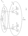
- FIG. 3 shows, as an example, a radio access network 300 where a plurality of transceiver network elements 301 is connected to a packet-switched network 310 which typically includes a plurality of routers 311.
- the transceiver network elements 301 are connected to routers 311, and the routers 311 provide packet-switched connectivity between the transceiver network elements 301.
- the link level connectivity between the transceiver network elements 301 and routers 311 may be provided, for example, by Asynchronous Transfer Mode (ATM) connections, or by radio or microwave links.
- ATM Asynchronous Transfer Mode
- the packet-switched network is typically connected via a gateway network element 312 to public data network 320 and/or to other data networks.
- embodiments of the present invention may be applicable to any data transfer from a communication device where retransmissions are used, especially in non-hierarchical wireless communication systems.
- uplink channels Two specific examples of uplink channels, where embodiments of the invention are applicable, are HSUPA and 3GPP Release 99 uplink channels.
- HSUPA power control and re-transmissions of low protocol layer data blocks are in use between a communications device and a transceiver network element.
- a low protocol layer refers here typically to physical layer or medium access control layer data blocks.
- link layer retransmissions RLC retransmissions
- HARQ Hydrid Automatic Repeat reQuest
- FEC forward error correction
- ARQ Automatic Repeat reQuest
- a receiver acknowledges a successfully received frame with an ACK message. Upon receipt of ACK, the transmitter knows that retransmissions are unnecessary. If a frame is received in error, the receiver sends a negative acknowledgement NACK to the transmitter and saves the received symbols. The transmitter consequently retransmits the frame. The receiver receives second symbols relating to the retransmitted frame, and soft-combines the stored first symbols and the received second symbols.
- This soft-combining reduces the error rate of the retransmitted frames, as previously received information relating to the same frame is employed.
- the retransmission may be identical and this is often referred to as soft-combining.
- the transmissions may not be identical. In this case the principle of incremental redundancy is used.
- Adaptive HARQ is a version of HARQ, where the data rate for each transmission and each retransmission may be adapted.
- the method for selecting the data rates in each retransmission is the same as that for selecting the data rates in each initial transmission.
- data blocks refer to a set of data blocks relating to each other, for example data blocks sent on a certain uplink channel or data blocks relating to a certain connection.
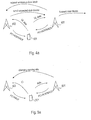
- FIG. 4a shows schematically functionality in accordance with a first embodiment of the invention.
- a communications device 101 is sending data in the uplink direction.
- a first transceiver network element 401 and a second transceiver network element 402 are receiving data blocks and acknowledging successful receipt of the data blocks.
- the data blocks may be sent on the HSUPA channel and HARQ may be used for acknowledging receipt of data blocks or the data blocks may be sent on a 3GPP Release 99 channel with link layer retransmissions.
- the communications device 101 should not retransmit a data block which is acknowledged by at least one transceiver network element.
- Both the first and the second transceiver network elements 401, 402 may send power control commands to the communications device 101.
- the communications device 101 adjusts the transmission power of the data blocks in accordance with the power control commands it receives.
- the first transceiver network element 401 in Figure 4a acts as a serving transceiver network element, and it performs macro diversity combining of data blocks.
- the data blocks are MAC data blocks. If some data blocks are not correctly received by the serving transceiver network element 401, it requests these data blocks (or at least parts of these data blocks) from the second transceiver network element 402.
- transmission resources between the transceiver network elements 401 and 402 are used more efficiently than by automatically sending all received data blocks from the second transceiver network element 402.
- FIG. 4a shows one transceiver network element 402, there may be more than one transceiver network element (in addition to the serving transceiver network element 401) receiving data blocks from the communications device 101 and sending acknowledgement information relating to the received data blocks to the communications device 101.
- the serving transceiver network element is typically changed from the transceiver network element 401 to one of the second transceiver network elements 402, in other words to one of the transceiver network elements with the active set. Any changes to active set are typically performed in between carrying out changes of the serving transceiver network element.
- the active set of the communications device 101 refers to those transceiver network elements which send acknowledgment information to the communications device 101 relating to the uplink data blocks and which also typically send power control commands to the communications device.
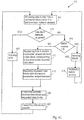
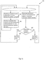
- Figure 4b shows, as an example, a flowchart of a method 410 of operating a serving transceiver network element 401. It is appreciated that only those steps, which are important for understanding the principle of the invention are shown in this flowchart and other appended flowcharts. It is also appreciated that the order of the steps may vary from the order shown in the flowcharts. Regarding the logic of sending AKC and NACK messages, it is appreciated that the appended flowcharts are intended to be only examples. For example, various details of HARQ are not discussed in connection with the appended flowcharts.
- the method 410 relates to processing data block in a serving transceiver network element 401.
- a data block is received from the communications device 101.
- the data block may be sent on a HSUPA channel.
- a data block corresponding to the erroneously received data block or a part of that data block is requested from a second transceiver network element 402 in step 417.
- the requested (part of) data block is received from the second transceiver network element 402 in the serving network element 401.
- the serving transceiver network element combines correctly received data blocks and requested data blocks.
- data blocks or upper protocol layer data packets formed of the data blocks are forwarded from the serving transceiver network element 401 towards the communications system.
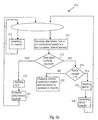
- Figure 4c shows, as an example, a flowchart of a method 450 of operating an assisting transceiver network element 402.
- a data block from the communications device is received in step 451, it is checked in step 452 whether the data block is correctly received.
- an acknowledgement is sent in step 453 or a non-acknowledgement is sent in step 454.
- the method 450 contains no check relating to the NACK counter values, as the serving transceiver network element 401 may be responsible for triggering upper layer retransmissions in response to not receiving requested data blocks from the transceiver network element 402.
- step 455 When a request to send a data block to a first transceiver network element 401 is received in step 455, the requested data block is sent in step 456 to the first transceiver network element 401, if it has been correctly received in the second transceiver network element 402.
- the serving transceiver network element 401 and the second transceiver network element(s) 402 typically control the transmission power used by the communications device 101 for transmitting the data block.
- FIG. 5a shows schematically functionality in accordance with a second embodiment of the invention.
- There is one serving transceiver network element 501 which receives data blocks from the communications device 101 and sends acknowledgement information to the communications device 101.
- the active set typically consists of the first transceiver network element 501 and of the second transceiver network element(s) 502. Change of the serving transceiver network element is carried out typically within the active set. In other words, change of the serving transceiver network elements takes place from the first transceiver network element 501 to (one of) the second transceiver network element(s) 502.
- the transceiver network element 502 need not properly process the data blocks and determine whether transmission errors have occurs in connection with the data blocks. It is sufficient that the transceiver network element 502 sends negative acknowledgement information in response to noticing a data block sent by the communications device 101. Therefore the term noticing a data block is used for the transceiver network element 502 instead of receiving data blocks. In practice the signal sent by a communications device 101 is demodulated in the second transceiver network element 502 for noticing a data block sent by the communications device 101.
- the serving transceiver network element is typically changed at the end of a data packet, a data packet consisting of a plurality of data blocks (excluding, for example, header information). This way complete data packets may be forwarded from the serving transceiver network element further to the communications system. If a need to change the serving transceiver network element is noticed when only some data blocks relating to a data packet have been received, the already received data blocks may be transmitted from the current serving transceiver network element to the new serving transceiver network element. If the communications system (the serving transceiver network element) decides to change the serving transceiver network element, no modifications are typically needed in the communications device.
- the change of the serving transceiver network element may be performed each time an end of a data packet is encountered. If the change of the serving transceiver network element at the end of each data packet is initiated by the communications device, functionality of the communications device typically needs to be modified accordingly. It is appreciated that a change of a serving network element initiated by the communications device is often called a cell reselection. It is possible that the network is responsible for initiating change of the serving transceiver network element each time an end of a data packet is encountered. The change may be carried out in a fast manner, as there is no need to perform control signaling with the communications device 101.
- the transfer takes about 188 ms.
- the change of the serving site should take a couple of milliseconds to be feasible, and due to not needing signaling between the network and the communications device 101 this can be achieved.
- the serving transceiver network element for the uplink data blocks may be changed to one of the second transceiver network elements 502.
- the serving transceiver network element is changed when the currently serving transceiver network element 501 notices a need for the change. For example, there may be need to change the serving site if the communications device 101 cannot receive the acknowledgement information sent by the serving transceiver network element 501. This can be noticed by the communications device 101 retransmitting a data block after the serving transceiver network element 501 has acknowledged the data block. Alternatively or additionally, unsuccessful receipt of a data block despite the maximum number retransmission may indicate a need for relocating the serving transceiver network element.
- weak pilot signal levels of the serving transceiver network element reported by the communications device and/or too high error rates of the data blocks received from the communications device may trigger change of the serving site.
- Various ways to detect a need for a serving site change are known to a skilled person.
- the communications device 101 in the situation shown in Figure 5a believes that it is in a soft handover.
- the communications device 101 need not know that only one of the transceiver network elements belonging to its active set is properly receiving and processing the data blocks sent by the communications device 101 and other transceiver network elements of the active set are sending just negative acknowledgements. There is thus no need to change functionality of a communications device that can perform a soft handover.
- Soft handover here refers to receiving acknowledgment information and typically also power control commands from more than one transceiver network element. By sending power control commands from all transceiver network elements of the active set in accordance with suitable power control procedures, the interference between the transceiver network elements can be properly controlled.
- FIG. 5b shows, as an example, a flowchart of a method 510 of operating a serving transceiver network element 501 in accordance with the first alternative of the second embodiment.
- Steps 411 to 416 are similar to steps in the method 410 in Figure 4b .
- a data block has been successfully received for the first time (steps 509, 412 and 413), it is checked whether an end of a data packet is encountered in step 511. If a data packet can be assembled from the data blocks received so far (it is possible that the data blocks are not successfully received in a correct order), the data packet is forwarded in step 512.
- data blocks may be forwarded block by block, for example, in the order as they successfully arrive.
- step 509 when a data block has been received in step 411, it is first checked whether the data packet has already been received and acknowledged. If this is the case, the communications device 101 may not be able to receive the acknowledgements sent by the serving transceiver network element 501 and there may be need for initiating change of the serving transceiver network element to (one of) the second transceiver network elements 502 (step 515). If the change of the serving transceiver network entity is initiated in step 515, in step 516 it may be checked whether the end of a data packet has been encountered when processing the latest successfully received data block. If the end of a data packet has not been encountered, data blocks relating to an incompletely received data packet are forwarded to the new serving transceiver network element in step 517.
- transceiver network element 501 sends also power control commands to the communications device 101, although this is not explicitly mentioned in Figure 5b .
- FIG. 5c shows, as an example, a flowchart of a method 550 of operating an assisting transceiver network element 502 belonging to the active set of the communications device.
- the transceiver network element 502 notices a data block sent by the communications device 101 (step 551).
- negative acknowledgement information is sent to the communications device 101 (step 552).
- the transceiver network element 502 sends also power control commands to the communications device 101, although this is not explicitly mentioned in Figure 5c .
- the transceiver network element 502 may receive data blocks from the previous serving transceiver network element in step 554. Thereafter the method 550 typically continues similarly as the method 510.
- the serving transceiver network element in the uplink direction may be a separate network element from the serving transceiver network element in the downlink direction (if the communications device is assigned a serving site in the downlink direction). Especially if the uplink serving site is changed at the end of each data packet, the downlink serving site may be changed independently of the uplink serving site.
- the change of the serving transceiver network element is not necessarily done in the end of a data packet.
- the serving uplink transceiver network element may be changed together with a change of the serving transceiver network element in the downlink direction.
- the downlink serving site is typically changed based on the network algorithms. The decision can be based, for example, on the pilot signal measurement reporting from the mobile or on the relative uplink measurements from different base stations.
- a method in accordance the second alternative of the second embodiment would not necessarily contain steps 511,516 and 517.
- the change of a downlink serving site would, however, lead to step 515.
- a further variant of the second embodiment is that the change of a downlink serving site causes change of the uplink serving site at the end of a next data packet.
- the uplink serving site is changed at the end of a data packet, the possibly are ready received data blocks relating to a next data packet are typically forwarded to the new serving site.
- the new serving site can then forward a complete data packet to the communications system after receiving rest of the data blocks relating to this data packet from the communications device 101.
- a communications device 101 in the situations described in Figure 5a believes that it is in a soft handover. It never receives positive acknowledgment information from the transceiver network elements 502 belonging to its active set, but the soft-handover functionality in the communications device 101 is able to cope with these situations.
- FIG 6a shows schematically functionality in accordance with a third embodiment of the invention.
- the serving transceiver network element 601 receives data blocks sent by the communications device 101 and sends acknowledgement information and typically also power control commands accordingly to the communications device 101.
- the second transceiver network element 602 is synchronized with the physical transmission channel relating to the data blocks sent by the communications device.
- the second transceiver network element 602 determines the quality of the uplink radio path and reports the quality to the serving transceiver network element 601.
- the communications device 101 in Figure 6a may believe that it is performing a basic hard handover, whereas the communication system is performing a prepared hard handover.
- Information about the quality of the uplink radio path is typically determined based on the received signal quality or pilot bit error rate.
- FIG. 6b shows, as an example, a flowchart of a method 610 of operating a serving transceiver network element 601. Steps 411 to 416 are similar to steps methods 410 and 510.
- step 613 information about the quality of the uplink radio path is received from (at least one of) the second transceiver network element(s) 602. If the retransmissions cannot provide successful receipt of data blocks, the serving transceiver network element may be changed in step 712 based on the received information about the quality of the uplink radio path. Furthermore, based on the quality of the uplink quality relating to the mobile station the serving transceiver network element 601 may initiate change of the serving site. Triggering of the change of the serving site may thus be based on uplink quality and/or retransmissions.
- FIG. 6c shows, as an example, a flowchart of a method 650 of operating an assisting transceiver network element 602.
- the transceiver network element 602 synchronizes with data blocks sent by the communications device 101.
- the transceiver network element 602 reports uplink quality between the communications device 101 and the transceiver network element 602 to the serving transceiver network element 601.
- the transceiver network element 602 may become the new serving transceiver network element. In that case, the transceiver network element 602 continues operation in accordance with the method 610.
- the assisting transceiver network entity 602 sends power control commands to the communications device 101.
- the power control target values are typically adjusted so that the assisting transceiver network element 602 has less influence on the power level of the communications device 101 than the serving transceiver network element 601.
- the functionality in accordance with an embodiment of the invention may be implemented, for example, by providing a suitable adapter device to be connected to or inserted into a transceiver network element for a cellular communications system.
- the adapter device provides additional functionality to a standard transceiver network element.
- the adapter device may be, for example, a plug-in card or a separate adapter device to be placed adjacent to an existing transceiver network element.
- the adapter would support the following features relating to the serving site: requesting erroneously received data blocks from an assisting site and combining received and requested data blocks.
- the adapter would support the following feature for the assisting site: sending only requested data blocks from non-serving site instead of sending all received data blocks.
- the adapter would support the following functionality. Only the serving site sends ACK messages for received data blocks, other sites in the active set send only NACKs. Changing serving site should be done only within the active set.. At least in accordance with the first alternative, the serving site is changed in the end of a data packet and already received data blocks are forwarded from a previous serving site to a new serving site. The serving site change may be done at the end of each data packet or it may be trigger by some other criterion. As one example, the uplink serving site may be changed in conjunction with the change of the downlink serving site.
- the adapter would support the following functionality.
- the serving site receives UL reports from at least other site and decides about change of the service site, for example, based on the UL reports and/or retransmissions.
- the at least one other site is synchronized with the data blocks sent by the communications device, and they send UL reports.
- transceiver network element in accordance with embodiments of the invention is arranged to act as a serving transceiver network element and as an assisting transceiver network element, as needed. There may be reasons, however, to set up specific transceiver network elements to operate only as assisting transceiver network elements or only as serving transceiver network elements.
- communications device refers here to any communications device capable of communicating via a communications system.
- communications devices are user equipment, mobile telephones, mobile stations, personal digital assistants, laptop computers and the like.
- a communications device need not be a device directly used by human users.
- serving transceiver network element refers to a transceiver network element primarily responsible for controlling transfer of data blocks from a communications device.
- the serving transceiver network element controls (at least partly) the transmission power of the communications device by sending power control commands.
- assisting transceiver network element refers to a transceiver network element at least paying attention to (noticing) data blocks sent by a communications device.
- the assisting transceiver network element may receive and process the data blocks properly for enabling sending them further, for example, to the serving transceiver network element, but for sending negative acknowledgement information and for sending power control commands this is not necessary.
- the assisting transceiver network element may send acknowledgement information, which may be either positive and negative acknowledgement messages or only negative acknowledgment messages.
- acknowledgement information may be either positive and negative acknowledgement messages or only negative acknowledgment messages.
- the assisting transceiver network element sends power control commands to the communications device for controlling uplink interference.
- the assisting transceiver network element may discard sending of acknowledgment information.
- the assisting transceiver network element sends power control commands for controlling uplink interference.
- the target value for the power control typically reflects an uplink transmission quality (for example, block error rate) that should be reached.
- the serving site has a stricter target value than the assisting site.
- a computer program in accordance with an embodiment of the invention may be embodied on a record medium, stored in a computer memory or carried on an electrical carrier signal.
Landscapes
- Engineering & Computer Science (AREA)
- Computer Networks & Wireless Communication (AREA)
- Signal Processing (AREA)
- Quality & Reliability (AREA)
- Mobile Radio Communication Systems (AREA)
Claims (17)
- Verfahren zum Verarbeiten von Aufwärtsdaten in einem Funkzugangsnetzwerk eines zellularen Kommunikationssystems, wobei das Verfahren Folgendes umfasst:Empfangen von Datenblöcken in einer Aufwärtsrichtung von einer Teilnehmereinrichtung (101) in einem bedienenden Sendeempfängernetzwerkelement (401) über eine drahtlose Schnittstelle;Überprüfen, ob die Datenblöcke am bedienenden Sendeempfängernetzwerkelement (401) korrekt empfangen wurden;Anfordern durch das bedienende Sendeempfängernetzwerkelement (401) von einem weiteren Sendeempfängernetzwerkelement (402) mindestens eines Teils von mindestens einem Datenblock, der mindestens einem irrtümlich empfangenen Datenblock entspricht, wobei das weitere Sendeempfängernetzwerkelement (402) dazu ausgelegt ist, Datenblöcke von der Teilnehmereinrichtung über eine drahtlose Schnittstelle zu empfangen; undEmpfangen des mindestens einen Teils des mindestens einen Datenblocks vom weiteren Sendeempfängernetzwerkelement (402).
- Verfahren nach Anspruch 1, das das Senden von Informationen, die anzeigen, ob Datenblöcke vom bedienenden Sendeempfängernetzwerkelement korrekt empfangen wurden, vom bedienenden Sendeempfängernetzwerkelement (401) an die Teilnehmereinrichtung (101) umfasst.
- Verfahren nach Anspruch 1 oder 2, das das Weiterleiten durch das bedienende Sendeempfängernetzwerkelement (401) von Informationen, die in korrekt empfangenen Datenblöcken und angeforderten Datenblöcken empfangen wurden, zu einem routenden Netzwerkelement umfasst.
- Verfahren nach Anspruch 1 oder 2, das Folgendes umfasst:Kombinieren am bedienenden Sendeempfängernetzwerkelement (301) von mindestens einem Datenblock, der von der Teilnehmereinrichtung (101) empfangen wurde, und des mindestens einen Teils von mindestens einem Datenblock, um einen diversitätkombinierten Datenstrom zu bilden; undWeiterleiten des diversitätkombinierten Datenstroms zu einem routenden Netzwerkelement (311).
- Verfahren nach Anspruch 1, das Folgendes umfasst:Empfangen von Datenblöcken von der Teilnehmereinrichtung (101) im weiteren Sendeempfängernetzwerkelement (402);Empfangen am weiteren Sendeempfängernetzwerkelement (402) einer Anforderung, den mindestens einen Teil von mindestens einem Datenblock zu senden; undSenden des mindestens einen Teils des mindestens einen Datenblocks vom weiteren Sendeempfängernetzwerkelement (402) an das bedienende Sendeempfängernetzwerkelement (401) .
- Verfahren nach einem der Ansprüche 1 bis 5, wobei das Anfordern durchgeführt wird, wenn ein Zähler für die Anzahl von Malen, die eine negative Bestätigung des irrtümlich empfangenen Datenblocks gesendet wurde, einen Schwellenwert erreicht.
- Verfahren nach einem der Ansprüche 1 bis 6, das, wenn das Anfordern nicht dazu führt, dass der mindestens eine Teil von mindestens einem Datenblock vom weiteren Sendeempfängernetzwerkelement (402) empfangen wird, das Auslösen einer Neuübertragung in der oberen Schicht für den mindestens einen Datenblock umfasst.
- Verfahren nach einem der Ansprüche 1 bis 7, wobei das Verfahren das Ändern des Sendeempfängernetzwerkelements, das die Teilnehmereinrichtung bedient, vom bedienenden Sendeempfängernetzwerkelement (401) in das weitere Sendeempfängernetzwerkelement (402) umfasst.
- Sendeempfängernetzwerkelement (401) für ein zellulares Kommunikationssystem, das Folgendes umfasst:Mittel zum Empfangen von Datenblöcken in einer Aufwärtsrichtung von einer Teilnehmereinrichtung (101) über eine drahtlose Schnittstelle;Mittel zum Überprüfen, ob die Datenblöcke korrekt empfangen wurden;Mittel zum Anfordern von einem zweiten Sendeempfängernetzwerkelement (402) mindestens eines Teils von mindestens einem Datenblock, der mindestens einem irrtümlich empfangenen Datenblock entspricht, wobei das zweite Sendeempfängernetzwerkelement (402) dazu ausgelegt ist, Datenblöcke von der Teilnehmereinrichtung über eine drahtlose Schnittstelle zu empfangen; undEmpfangen des mindestens einen Teils des mindestens einen Datenblocks vom zweiten Sendeempfängernetzwerkelement (402),wobei das Sendeempfängernetzwerkelement (401) als ein bedienendes Sendeempfängernetzwerkelement für die Teilnehmereinrichtung (101) ausgelegt ist.
- Sendeempfängernetzwerkelement (401) nach Anspruch 9, das Folgendes umfasst:
Mittel zum Senden mindestens eines Teils von mindestens einem Datenblock, der von einer weiteren Teilnehmereinrichtung empfangen wurde, an ein drittes Sendeempfängernetzwerkelement, wenn das Sendeempfängernetzwerkelement (401) als ein assistierendes Sendeempfängernetzwerkelement für die weitere Teilnehmereinrichtung ausgelegt ist. - Sendeempfängernetzwerkelement (401) nach Anspruch 9 oder 10, das Mittel zum Weiterleiten von Informationen, die in korrekt empfangenen Datenblöcken und angeforderten Datenblöcken empfangen wurden, zu einem routenden Netzwerkelement umfasst.
- Sendeempfängernetzwerkelement (401) nach Anspruch 9 oder 10, das Folgendes umfasst:Kombinationsmittel zum Kombinieren von mindestens einem Datenblock, der von der Teilnehmereinrichtung (101) empfangen wurde, und des mindestens einen Teils von mindestens einem Datenblock, um einen diversitätkombinierten Datenstrom zu bilden; undWeiterleitungsmittel zum Weiterleiten des diversitätkombinierten Datenstroms zu einem routenden Netzwerkelement (311).
- Sendeempfängernetzwerkelement (401) nach einem der Ansprüche 9 bis 12, wobei das Anfordern durchgeführt wird, wenn ein Zähler für die Anzahl von Malen, die eine negative Bestätigung des irrtümlich empfangenen Datenblocks gesendet wurde, einen Schwellenwert erreicht.
- Sendeempfängernetzwerkelement (401) nach einem der Ansprüche 9 bis 13, das, wenn das Anfordern nicht dazu führt, dass der mindestens eine Teil von mindestens einem Datenblock vom weiteren Sendeempfängernetzwerkelement (402) empfangen wird, Mittel zum Auslösen einer Neuübertragung in der oberen Schicht für den mindestens einen Datenblock umfasst.
- Sendeempfängernetzwerkelement (401) nach einem der Ansprüche 9 bis 14, das Mittel zum Ändern des bedienenden Sendeempfängernetzwerkelements vom Sendeempfängernetzwerkelement (401) in das weitere Sendeempfängernetzwerkelement (402) umfasst.
- Zellulares Kommunikationssystem, das Folgendes umfasst:
Mittel zum Empfangen von Datenblöcken in einer Aufwärtsrichtung von einer Teilnehmereinrichtung (101) in einem bedienenden Sendeempfängernetzwerkelement (401) über eine drahtlose Schnittstelle:Mittel zum Überprüfen, ob die Datenblöcke im bedienenden Sendeempfängernetzwerkelement (401) korrekt empfangen wurden:Mittel zum Anfordern von einem weiteren Sendeempfängernetzwerkelement (402) mindestens eines Teils von mindestens einem Datenblock, der mindestens einem irrtümlich empfangenen Datenblock entspricht, wenn das bedienende Sendeempfängernetzwerkelement (401) als ein bedienendes Sendeempfängernetzwerkelement für die Teilnehmereinrichtung ausgelegt ist, wobei das weitere Sendeempfängernetzwerkelement (402) dazu ausgelegt ist, Datenblöcke von der Teilnehmereinrichtung über eine drahtlose Schnittstelle zu empfangen; undMittel zum Senden des mindestens einen Teils von mindestens einem Datenblock vom weiteren Sendeempfängernetzwerkelement (402) an das bedienende Sendeempfängernetzwerkelement (401). - Computerprogramm, das in einem computerlesbaren Medium enthalten ist, das Anweisungen umfasst, die, wenn das Programm von einem Computer ausgeführt wird, den Computer veranlassen, die Schritte des Verfahrens nach einem der Ansprüche 1-8 umzusetzen.
Applications Claiming Priority (2)
| Application Number | Priority Date | Filing Date | Title |
|---|---|---|---|
| FI20050114A FI20050114A0 (fi) | 2005-02-01 | 2005-02-01 | Nousevalta siirtotieltä tulevan datan käsittely viestintäjärjestelmässä |
| PCT/FI2005/000480 WO2006082272A1 (en) | 2005-02-01 | 2005-11-10 | Processing of uplink data in a communications system |
Publications (3)
| Publication Number | Publication Date |
|---|---|
| EP1844570A1 EP1844570A1 (de) | 2007-10-17 |
| EP1844570A4 EP1844570A4 (de) | 2011-07-06 |
| EP1844570B1 true EP1844570B1 (de) | 2018-10-17 |
Family
ID=34224157
Family Applications (1)
| Application Number | Title | Priority Date | Filing Date |
|---|---|---|---|
| EP05807901.3A Expired - Lifetime EP1844570B1 (de) | 2005-02-01 | 2005-11-10 | Verarbeitung von aufwärtsstreckendaten in einem kommunikationssystem |
Country Status (4)
| Country | Link |
|---|---|
| US (1) | US8934935B2 (de) |
| EP (1) | EP1844570B1 (de) |
| FI (1) | FI20050114A0 (de) |
| WO (1) | WO2006082272A1 (de) |
Families Citing this family (12)
| Publication number | Priority date | Publication date | Assignee | Title |
|---|---|---|---|---|
| US20060198336A1 (en) * | 2005-03-03 | 2006-09-07 | Nokia Corporation | Deployment of different physical layer protocols in a radio access network |
| JP4898918B2 (ja) * | 2006-10-02 | 2012-03-21 | エルジー エレクトロニクス インコーポレイティド | 多重搬送波システムに用いられる再伝送方法 |
| CA2878737C (en) | 2006-10-03 | 2018-10-02 | Interdigital Technology Corporation | Combined open loop/closed loop (cqi-based) uplink transmit power control with interference mitigation for e-utra |
| KR101397135B1 (ko) | 2007-03-07 | 2014-05-22 | 인터디지탈 테크날러지 코포레이션 | 이동국의 업링크 전력을 제어하기 위한 결합형 개방 루프/폐쇄 루프 방법 |
| US8301954B2 (en) * | 2007-07-04 | 2012-10-30 | Telefonaktiebolaget L M Ericsson (Publ) | Method and arrangement in a communication network system |
| US20090031185A1 (en) * | 2007-07-23 | 2009-01-29 | Texas Instruments Incorporated | Hybrid arq systems and methods for packet-based networks |
| WO2010016669A2 (en) * | 2008-08-04 | 2010-02-11 | Samsung Electronics Co., Ltd. | Signal transmission method and apparatus for user equipment in mobile communication system |
| US20110286404A1 (en) * | 2009-11-20 | 2011-11-24 | Qualcomm Incorporated | Method and apparatus for seamless transitions of transfer between radio links for data reception |
| US20110286322A1 (en) * | 2009-11-20 | 2011-11-24 | Qualcomm Incorporated | Method and apparatus for seamless transitions of data transmission transfer between radio links |
| JP2011223127A (ja) * | 2010-04-06 | 2011-11-04 | Sharp Corp | 移動局装置、無線通信方法および集積回路 |
| CN102264131B (zh) * | 2010-05-29 | 2015-03-11 | 华为技术有限公司 | 无线网络中的数据传输方法和装置 |
| US20110317642A1 (en) * | 2010-06-25 | 2011-12-29 | Qualcomm Incorporated | System and process for transmission sequence number management in an intra-node b unsynchronized serving cell change |
Citations (2)
| Publication number | Priority date | Publication date | Assignee | Title |
|---|---|---|---|---|
| US20040160925A1 (en) * | 2003-02-14 | 2004-08-19 | Samsung Electronics Co., Ltd. | System and method for retransmitting uplink data in a code division multiple access communication system |
| WO2005022798A1 (en) * | 2003-08-25 | 2005-03-10 | Interdigital Technology Corporation | Enhanced uplink operation in soft handover |
Family Cites Families (9)
| Publication number | Priority date | Publication date | Assignee | Title |
|---|---|---|---|---|
| US5541927A (en) | 1994-08-24 | 1996-07-30 | At&T Corp. | Method of multicasting |
| FI109251B (fi) * | 1999-09-10 | 2002-06-14 | Nokia Corp | Tiedonsiirtomenetelmä, radiojärjestelmä, radiolähetin ja radiovastaanotin |
| US6678523B1 (en) | 2000-11-03 | 2004-01-13 | Motorola, Inc. | Closed loop method for reverse link soft handoff hybrid automatic repeat request |
| JP3844957B2 (ja) | 2000-11-15 | 2006-11-15 | 株式会社エヌ・ティ・ティ・ドコモ | 再送制御方法及び装置 |
| JP3742760B2 (ja) * | 2001-07-03 | 2006-02-08 | 松下電器産業株式会社 | 無線通信システム及び無線通信方法 |
| US6665283B2 (en) * | 2001-08-10 | 2003-12-16 | Motorola, Inc. | Method and apparatus for transmitting data in a packet data communication system |
| AU2003201057A1 (en) | 2002-02-14 | 2003-09-04 | Nokia Corporation | Physical layer packet retransmission handling in wcdma in soft handover |
| SE0301076D0 (sv) | 2003-04-08 | 2003-04-08 | Ericsson Telefon Ab L M | A method in a telecommunication system |
| JP4842970B2 (ja) * | 2004-12-22 | 2011-12-21 | クゥアルコム・インコーポレイテッド | 多元接続通信ネットワークにおける柔軟性のあるホッピングのための方法と装置 |
-
2005
- 2005-02-01 FI FI20050114A patent/FI20050114A0/fi not_active Application Discontinuation
- 2005-06-10 US US11/149,148 patent/US8934935B2/en not_active Expired - Fee Related
- 2005-11-10 EP EP05807901.3A patent/EP1844570B1/de not_active Expired - Lifetime
- 2005-11-10 WO PCT/FI2005/000480 patent/WO2006082272A1/en not_active Ceased
Patent Citations (2)
| Publication number | Priority date | Publication date | Assignee | Title |
|---|---|---|---|---|
| US20040160925A1 (en) * | 2003-02-14 | 2004-08-19 | Samsung Electronics Co., Ltd. | System and method for retransmitting uplink data in a code division multiple access communication system |
| WO2005022798A1 (en) * | 2003-08-25 | 2005-03-10 | Interdigital Technology Corporation | Enhanced uplink operation in soft handover |
Also Published As
| Publication number | Publication date |
|---|---|
| FI20050114A0 (fi) | 2005-02-01 |
| EP1844570A1 (de) | 2007-10-17 |
| US20060171349A1 (en) | 2006-08-03 |
| WO2006082272A1 (en) | 2006-08-10 |
| EP1844570A4 (de) | 2011-07-06 |
| US8934935B2 (en) | 2015-01-13 |
Similar Documents
| Publication | Publication Date | Title |
|---|---|---|
| US11265788B2 (en) | Method and apparatus for transmitting data via a plurality of cells | |
| US11259228B2 (en) | Supporting uplink transmissions | |
| CN101971546B (zh) | 无线通信系统中的方法和布置 | |
| EP1507421B1 (de) | Synchronisation von Basisstationen während Soft-Handover | |
| CA2774295C (en) | Method and apparatus for resegmentation of packet data for retransmission on harq transmission failure | |
| US20050237932A1 (en) | Method and system for rate-controlled mode wireless communications | |
| EP1560452A2 (de) | Verfahren zur effizienten Übertragung von Daten während eines Weiterreichens in einem Breitband-Funkzugriffsnetz | |
| JP2004511950A (ja) | 情報通信方法及びその方法を使用する装置 | |
| US8181080B2 (en) | Adaptive HARQ control for EDCH | |
| WO2008110104A1 (fr) | Procédé, station de base et système de réseau d'accès radio permettant de configurer une valeur de décalage de puissance e-hich | |
| JP2005006320A (ja) | 無線通信ネットワーク、無線通信局、およびデータ・パケットを送信する方法 | |
| EP1844570B1 (de) | Verarbeitung von aufwärtsstreckendaten in einem kommunikationssystem | |
| EP2253161B1 (de) | Bereitstellung einer bestätigung einer hs-dsch-zelle | |
| JP2009517967A (ja) | 移動通信ネットワークにおける装置および方法 | |
| CN101002440B (zh) | 无线通信系统中的分组传输确认 | |
| AU2005272274B2 (en) | Packet transmission acknowledgement in wireless communication system | |
| WO2007025459A1 (fr) | Methode de transfert en douceur d'un terminal utilisateur entre stations de base | |
| US20250300771A1 (en) | PERFORMANCE OPTIMIZATIONS FOR eMMB and URLLC APPLICATIONS WITH HIGH RELIABILITY REQUIREMENTS | |
| EP4622153A1 (de) | Leistungsoptimierungen für emmb- und urllc-anwendungen mit hochzuverlässigen anforderungen | |
| KR101173702B1 (ko) | 이동통신 시스템에서 스케줄링 정보를 전송하는 방법 및장치 | |
| EP2262302A1 (de) | Telekommunikationsverfahren, System und Vorrichtung |
Legal Events
| Date | Code | Title | Description |
|---|---|---|---|
| PUAI | Public reference made under article 153(3) epc to a published international application that has entered the european phase |
Free format text: ORIGINAL CODE: 0009012 |
|
| 17P | Request for examination filed |
Effective date: 20070803 |
|
| AK | Designated contracting states |
Kind code of ref document: A1 Designated state(s): AT BE BG CH CY CZ DE DK EE ES FI FR GB GR HU IE IS IT LI LT LU LV MC NL PL PT RO SE SI SK TR |
|
| RIN1 | Information on inventor provided before grant (corrected) |
Inventor name: HAEKKINEN, HANNU Inventor name: HOLMA, HARRI |
|
| DAX | Request for extension of the european patent (deleted) | ||
| A4 | Supplementary search report drawn up and despatched |
Effective date: 20110607 |
|
| 17Q | First examination report despatched |
Effective date: 20120613 |
|
| RAP1 | Party data changed (applicant data changed or rights of an application transferred) |
Owner name: NOKIA CORPORATION |
|
| RAP1 | Party data changed (applicant data changed or rights of an application transferred) |
Owner name: NOKIA TECHNOLOGIES OY |
|
| STAA | Information on the status of an ep patent application or granted ep patent |
Free format text: STATUS: EXAMINATION IS IN PROGRESS |
|
| REG | Reference to a national code |
Ref country code: DE Ref legal event code: R079 Ref document number: 602005054811 Country of ref document: DE Free format text: PREVIOUS MAIN CLASS: H04L0001180000 Ipc: H04L0001000000 |
|
| GRAP | Despatch of communication of intention to grant a patent |
Free format text: ORIGINAL CODE: EPIDOSNIGR1 |
|
| STAA | Information on the status of an ep patent application or granted ep patent |
Free format text: STATUS: GRANT OF PATENT IS INTENDED |
|
| RIC1 | Information provided on ipc code assigned before grant |
Ipc: H04L 1/20 20060101ALI20180319BHEP Ipc: H04L 1/22 20060101ALI20180319BHEP Ipc: H04L 1/18 20060101ALI20180319BHEP Ipc: H04L 1/00 20060101AFI20180319BHEP |
|
| INTG | Intention to grant announced |
Effective date: 20180410 |
|
| GRAS | Grant fee paid |
Free format text: ORIGINAL CODE: EPIDOSNIGR3 |
|
| GRAJ | Information related to disapproval of communication of intention to grant by the applicant or resumption of examination proceedings by the epo deleted |
Free format text: ORIGINAL CODE: EPIDOSDIGR1 |
|
| GRAL | Information related to payment of fee for publishing/printing deleted |
Free format text: ORIGINAL CODE: EPIDOSDIGR3 |
|
| STAA | Information on the status of an ep patent application or granted ep patent |
Free format text: STATUS: EXAMINATION IS IN PROGRESS |
|
| GRAR | Information related to intention to grant a patent recorded |
Free format text: ORIGINAL CODE: EPIDOSNIGR71 |
|
| STAA | Information on the status of an ep patent application or granted ep patent |
Free format text: STATUS: GRANT OF PATENT IS INTENDED |
|
| GRAA | (expected) grant |
Free format text: ORIGINAL CODE: 0009210 |
|
| STAA | Information on the status of an ep patent application or granted ep patent |
Free format text: STATUS: THE PATENT HAS BEEN GRANTED |
|
| INTC | Intention to grant announced (deleted) | ||
| AK | Designated contracting states |
Kind code of ref document: B1 Designated state(s): AT BE BG CH CY CZ DE DK EE ES FI FR GB GR HU IE IS IT LI LT LU LV MC NL PL PT RO SE SI SK TR |
|
| INTG | Intention to grant announced |
Effective date: 20180911 |
|
| REG | Reference to a national code |
Ref country code: GB Ref legal event code: FG4D |
|
| REG | Reference to a national code |
Ref country code: CH Ref legal event code: EP |
|
| REG | Reference to a national code |
Ref country code: IE Ref legal event code: FG4D |
|
| REG | Reference to a national code |
Ref country code: DE Ref legal event code: R096 Ref document number: 602005054811 Country of ref document: DE Ref country code: AT Ref legal event code: REF Ref document number: 1055258 Country of ref document: AT Kind code of ref document: T Effective date: 20181115 |
|
| PGFP | Annual fee paid to national office [announced via postgrant information from national office to epo] |
Ref country code: DE Payment date: 20181030 Year of fee payment: 14 |
|
| REG | Reference to a national code |
Ref country code: NL Ref legal event code: MP Effective date: 20181017 |
|
| REG | Reference to a national code |
Ref country code: LT Ref legal event code: MG4D |
|
| REG | Reference to a national code |
Ref country code: AT Ref legal event code: MK05 Ref document number: 1055258 Country of ref document: AT Kind code of ref document: T Effective date: 20181017 |
|
| PG25 | Lapsed in a contracting state [announced via postgrant information from national office to epo] |
Ref country code: NL Free format text: LAPSE BECAUSE OF FAILURE TO SUBMIT A TRANSLATION OF THE DESCRIPTION OR TO PAY THE FEE WITHIN THE PRESCRIBED TIME-LIMIT Effective date: 20181017 |
|
| PG25 | Lapsed in a contracting state [announced via postgrant information from national office to epo] |
Ref country code: ES Free format text: LAPSE BECAUSE OF FAILURE TO SUBMIT A TRANSLATION OF THE DESCRIPTION OR TO PAY THE FEE WITHIN THE PRESCRIBED TIME-LIMIT Effective date: 20181017 Ref country code: IS Free format text: LAPSE BECAUSE OF FAILURE TO SUBMIT A TRANSLATION OF THE DESCRIPTION OR TO PAY THE FEE WITHIN THE PRESCRIBED TIME-LIMIT Effective date: 20190217 Ref country code: AT Free format text: LAPSE BECAUSE OF FAILURE TO SUBMIT A TRANSLATION OF THE DESCRIPTION OR TO PAY THE FEE WITHIN THE PRESCRIBED TIME-LIMIT Effective date: 20181017 Ref country code: LT Free format text: LAPSE BECAUSE OF FAILURE TO SUBMIT A TRANSLATION OF THE DESCRIPTION OR TO PAY THE FEE WITHIN THE PRESCRIBED TIME-LIMIT Effective date: 20181017 Ref country code: BG Free format text: LAPSE BECAUSE OF FAILURE TO SUBMIT A TRANSLATION OF THE DESCRIPTION OR TO PAY THE FEE WITHIN THE PRESCRIBED TIME-LIMIT Effective date: 20190117 Ref country code: PL Free format text: LAPSE BECAUSE OF FAILURE TO SUBMIT A TRANSLATION OF THE DESCRIPTION OR TO PAY THE FEE WITHIN THE PRESCRIBED TIME-LIMIT Effective date: 20181017 Ref country code: FI Free format text: LAPSE BECAUSE OF FAILURE TO SUBMIT A TRANSLATION OF THE DESCRIPTION OR TO PAY THE FEE WITHIN THE PRESCRIBED TIME-LIMIT Effective date: 20181017 Ref country code: LV Free format text: LAPSE BECAUSE OF FAILURE TO SUBMIT A TRANSLATION OF THE DESCRIPTION OR TO PAY THE FEE WITHIN THE PRESCRIBED TIME-LIMIT Effective date: 20181017 |
|
| PG25 | Lapsed in a contracting state [announced via postgrant information from national office to epo] |
Ref country code: SE Free format text: LAPSE BECAUSE OF FAILURE TO SUBMIT A TRANSLATION OF THE DESCRIPTION OR TO PAY THE FEE WITHIN THE PRESCRIBED TIME-LIMIT Effective date: 20181017 Ref country code: GR Free format text: LAPSE BECAUSE OF FAILURE TO SUBMIT A TRANSLATION OF THE DESCRIPTION OR TO PAY THE FEE WITHIN THE PRESCRIBED TIME-LIMIT Effective date: 20190118 Ref country code: PT Free format text: LAPSE BECAUSE OF FAILURE TO SUBMIT A TRANSLATION OF THE DESCRIPTION OR TO PAY THE FEE WITHIN THE PRESCRIBED TIME-LIMIT Effective date: 20190217 |
|
| REG | Reference to a national code |
Ref country code: CH Ref legal event code: PL |
|
| REG | Reference to a national code |
Ref country code: DE Ref legal event code: R097 Ref document number: 602005054811 Country of ref document: DE |
|
| PG25 | Lapsed in a contracting state [announced via postgrant information from national office to epo] |
Ref country code: IT Free format text: LAPSE BECAUSE OF FAILURE TO SUBMIT A TRANSLATION OF THE DESCRIPTION OR TO PAY THE FEE WITHIN THE PRESCRIBED TIME-LIMIT Effective date: 20181017 Ref country code: DK Free format text: LAPSE BECAUSE OF FAILURE TO SUBMIT A TRANSLATION OF THE DESCRIPTION OR TO PAY THE FEE WITHIN THE PRESCRIBED TIME-LIMIT Effective date: 20181017 Ref country code: LU Free format text: LAPSE BECAUSE OF NON-PAYMENT OF DUE FEES Effective date: 20181110 Ref country code: CZ Free format text: LAPSE BECAUSE OF FAILURE TO SUBMIT A TRANSLATION OF THE DESCRIPTION OR TO PAY THE FEE WITHIN THE PRESCRIBED TIME-LIMIT Effective date: 20181017 |
|
| REG | Reference to a national code |
Ref country code: BE Ref legal event code: MM Effective date: 20181130 |
|
| REG | Reference to a national code |
Ref country code: IE Ref legal event code: MM4A |
|
| PLBE | No opposition filed within time limit |
Free format text: ORIGINAL CODE: 0009261 |
|
| STAA | Information on the status of an ep patent application or granted ep patent |
Free format text: STATUS: NO OPPOSITION FILED WITHIN TIME LIMIT |
|
| PG25 | Lapsed in a contracting state [announced via postgrant information from national office to epo] |
Ref country code: EE Free format text: LAPSE BECAUSE OF FAILURE TO SUBMIT A TRANSLATION OF THE DESCRIPTION OR TO PAY THE FEE WITHIN THE PRESCRIBED TIME-LIMIT Effective date: 20181017 Ref country code: CH Free format text: LAPSE BECAUSE OF NON-PAYMENT OF DUE FEES Effective date: 20181130 Ref country code: RO Free format text: LAPSE BECAUSE OF FAILURE TO SUBMIT A TRANSLATION OF THE DESCRIPTION OR TO PAY THE FEE WITHIN THE PRESCRIBED TIME-LIMIT Effective date: 20181017 Ref country code: SK Free format text: LAPSE BECAUSE OF FAILURE TO SUBMIT A TRANSLATION OF THE DESCRIPTION OR TO PAY THE FEE WITHIN THE PRESCRIBED TIME-LIMIT Effective date: 20181017 Ref country code: LI Free format text: LAPSE BECAUSE OF NON-PAYMENT OF DUE FEES Effective date: 20181130 Ref country code: MC Free format text: LAPSE BECAUSE OF FAILURE TO SUBMIT A TRANSLATION OF THE DESCRIPTION OR TO PAY THE FEE WITHIN THE PRESCRIBED TIME-LIMIT Effective date: 20181017 |
|
| RAP2 | Party data changed (patent owner data changed or rights of a patent transferred) |
Owner name: NOKIA TECHNOLOGIES OY |
|
| 26N | No opposition filed |
Effective date: 20190718 |
|
| GBPC | Gb: european patent ceased through non-payment of renewal fee |
Effective date: 20190117 |
|
| PG25 | Lapsed in a contracting state [announced via postgrant information from national office to epo] |
Ref country code: IE Free format text: LAPSE BECAUSE OF NON-PAYMENT OF DUE FEES Effective date: 20181110 Ref country code: FR Free format text: LAPSE BECAUSE OF NON-PAYMENT OF DUE FEES Effective date: 20181217 Ref country code: SI Free format text: LAPSE BECAUSE OF FAILURE TO SUBMIT A TRANSLATION OF THE DESCRIPTION OR TO PAY THE FEE WITHIN THE PRESCRIBED TIME-LIMIT Effective date: 20181017 |
|
| PG25 | Lapsed in a contracting state [announced via postgrant information from national office to epo] |
Ref country code: BE Free format text: LAPSE BECAUSE OF NON-PAYMENT OF DUE FEES Effective date: 20181130 |
|
| PG25 | Lapsed in a contracting state [announced via postgrant information from national office to epo] |
Ref country code: GB Free format text: LAPSE BECAUSE OF NON-PAYMENT OF DUE FEES Effective date: 20190117 |
|
| PG25 | Lapsed in a contracting state [announced via postgrant information from national office to epo] |
Ref country code: TR Free format text: LAPSE BECAUSE OF FAILURE TO SUBMIT A TRANSLATION OF THE DESCRIPTION OR TO PAY THE FEE WITHIN THE PRESCRIBED TIME-LIMIT Effective date: 20181017 |
|
| REG | Reference to a national code |
Ref country code: DE Ref legal event code: R119 Ref document number: 602005054811 Country of ref document: DE |
|
| PG25 | Lapsed in a contracting state [announced via postgrant information from national office to epo] |
Ref country code: HU Free format text: LAPSE BECAUSE OF FAILURE TO SUBMIT A TRANSLATION OF THE DESCRIPTION OR TO PAY THE FEE WITHIN THE PRESCRIBED TIME-LIMIT; INVALID AB INITIO Effective date: 20051110 Ref country code: CY Free format text: LAPSE BECAUSE OF FAILURE TO SUBMIT A TRANSLATION OF THE DESCRIPTION OR TO PAY THE FEE WITHIN THE PRESCRIBED TIME-LIMIT Effective date: 20181017 |
|
| PG25 | Lapsed in a contracting state [announced via postgrant information from national office to epo] |
Ref country code: DE Free format text: LAPSE BECAUSE OF NON-PAYMENT OF DUE FEES Effective date: 20200603 |