EP1844739A1 - Poignée courte pour une endoprothèse longue - Google Patents
Poignée courte pour une endoprothèse longue Download PDFInfo
- Publication number
- EP1844739A1 EP1844739A1 EP07007610A EP07007610A EP1844739A1 EP 1844739 A1 EP1844739 A1 EP 1844739A1 EP 07007610 A EP07007610 A EP 07007610A EP 07007610 A EP07007610 A EP 07007610A EP 1844739 A1 EP1844739 A1 EP 1844739A1
- Authority
- EP
- European Patent Office
- Prior art keywords
- sheath
- delivery system
- stent
- stent delivery
- keel
- Prior art date
- Legal status (The legal status is an assumption and is not a legal conclusion. Google has not performed a legal analysis and makes no representation as to the accuracy of the status listed.)
- Withdrawn
Links
- 210000003813 thumb Anatomy 0.000 claims description 25
- 238000000034 method Methods 0.000 description 3
- 238000005452 bending Methods 0.000 description 2
- 206010002329 Aneurysm Diseases 0.000 description 1
- 208000031481 Pathologic Constriction Diseases 0.000 description 1
- 239000000853 adhesive Substances 0.000 description 1
- 230000001070 adhesive effect Effects 0.000 description 1
- 239000008280 blood Substances 0.000 description 1
- 210000004369 blood Anatomy 0.000 description 1
- 230000001419 dependent effect Effects 0.000 description 1
- 201000010099 disease Diseases 0.000 description 1
- 208000037265 diseases, disorders, signs and symptoms Diseases 0.000 description 1
- 210000004247 hand Anatomy 0.000 description 1
- 238000004519 manufacturing process Methods 0.000 description 1
- 239000000463 material Substances 0.000 description 1
- 230000000452 restraining effect Effects 0.000 description 1
- 208000037804 stenosis Diseases 0.000 description 1
- 230000036262 stenosis Effects 0.000 description 1
- 230000002792 vascular Effects 0.000 description 1
- 238000003466 welding Methods 0.000 description 1
- 238000004804 winding Methods 0.000 description 1
Images



Classifications
-
- A—HUMAN NECESSITIES
- A61—MEDICAL OR VETERINARY SCIENCE; HYGIENE
- A61F—FILTERS IMPLANTABLE INTO BLOOD VESSELS; PROSTHESES; DEVICES PROVIDING PATENCY TO, OR PREVENTING COLLAPSING OF, TUBULAR STRUCTURES OF THE BODY, e.g. STENTS; ORTHOPAEDIC, NURSING OR CONTRACEPTIVE DEVICES; FOMENTATION; TREATMENT OR PROTECTION OF EYES OR EARS; BANDAGES, DRESSINGS OR ABSORBENT PADS; FIRST-AID KITS
- A61F2/00—Filters implantable into blood vessels; Prostheses, i.e. artificial substitutes or replacements for parts of the body; Appliances for connecting them with the body; Devices providing patency to, or preventing collapsing of, tubular structures of the body, e.g. stents
- A61F2/95—Instruments specially adapted for placement or removal of stents or stent-grafts
- A61F2/962—Instruments specially adapted for placement or removal of stents or stent-grafts having an outer sleeve
- A61F2/97—Instruments specially adapted for placement or removal of stents or stent-grafts having an outer sleeve the outer sleeve being splittable
-
- A—HUMAN NECESSITIES
- A61—MEDICAL OR VETERINARY SCIENCE; HYGIENE
- A61F—FILTERS IMPLANTABLE INTO BLOOD VESSELS; PROSTHESES; DEVICES PROVIDING PATENCY TO, OR PREVENTING COLLAPSING OF, TUBULAR STRUCTURES OF THE BODY, e.g. STENTS; ORTHOPAEDIC, NURSING OR CONTRACEPTIVE DEVICES; FOMENTATION; TREATMENT OR PROTECTION OF EYES OR EARS; BANDAGES, DRESSINGS OR ABSORBENT PADS; FIRST-AID KITS
- A61F2/00—Filters implantable into blood vessels; Prostheses, i.e. artificial substitutes or replacements for parts of the body; Appliances for connecting them with the body; Devices providing patency to, or preventing collapsing of, tubular structures of the body, e.g. stents
- A61F2/95—Instruments specially adapted for placement or removal of stents or stent-grafts
-
- A—HUMAN NECESSITIES
- A61—MEDICAL OR VETERINARY SCIENCE; HYGIENE
- A61F—FILTERS IMPLANTABLE INTO BLOOD VESSELS; PROSTHESES; DEVICES PROVIDING PATENCY TO, OR PREVENTING COLLAPSING OF, TUBULAR STRUCTURES OF THE BODY, e.g. STENTS; ORTHOPAEDIC, NURSING OR CONTRACEPTIVE DEVICES; FOMENTATION; TREATMENT OR PROTECTION OF EYES OR EARS; BANDAGES, DRESSINGS OR ABSORBENT PADS; FIRST-AID KITS
- A61F2/00—Filters implantable into blood vessels; Prostheses, i.e. artificial substitutes or replacements for parts of the body; Appliances for connecting them with the body; Devices providing patency to, or preventing collapsing of, tubular structures of the body, e.g. stents
- A61F2/95—Instruments specially adapted for placement or removal of stents or stent-grafts
- A61F2/9517—Instruments specially adapted for placement or removal of stents or stent-grafts handle assemblies therefor
-
- A—HUMAN NECESSITIES
- A61—MEDICAL OR VETERINARY SCIENCE; HYGIENE
- A61F—FILTERS IMPLANTABLE INTO BLOOD VESSELS; PROSTHESES; DEVICES PROVIDING PATENCY TO, OR PREVENTING COLLAPSING OF, TUBULAR STRUCTURES OF THE BODY, e.g. STENTS; ORTHOPAEDIC, NURSING OR CONTRACEPTIVE DEVICES; FOMENTATION; TREATMENT OR PROTECTION OF EYES OR EARS; BANDAGES, DRESSINGS OR ABSORBENT PADS; FIRST-AID KITS
- A61F2/00—Filters implantable into blood vessels; Prostheses, i.e. artificial substitutes or replacements for parts of the body; Appliances for connecting them with the body; Devices providing patency to, or preventing collapsing of, tubular structures of the body, e.g. stents
- A61F2/95—Instruments specially adapted for placement or removal of stents or stent-grafts
- A61F2/962—Instruments specially adapted for placement or removal of stents or stent-grafts having an outer sleeve
- A61F2/966—Instruments specially adapted for placement or removal of stents or stent-grafts having an outer sleeve with relative longitudinal movement between outer sleeve and prosthesis, e.g. using a push rod
Definitions
- the present invention relates to an intra-vascular device and method. More particularly, the present invention relates to a device for deployment of a stent for treatment of luminal, i.e., intra-vascular, diseases.
- a self-expanding stent was restrained within a sheath. After positioning of the stent at the desired location via fluoroscopic guidance, the physician retracted the sheath to deploy the stent, i.e., to expose the stent and allow it to self-expand. To completely deploy the stent, the physician had to retract the sheath over the entire length of the stent, which was relatively cumbersome and typically required the use of both hands of the physician in the case of long self-expanding stents.
- FIG. 1 is a partially cutaway delivery system 100 for deploying a stent 102 in accordance with the prior art.
- Stent 102 is a radially self-expanding stent.
- Delivery system 100 includes a pushrod 104 and a sheath 106, sometimes called a catheter sheath.
- Pushrod 104 includes a distal end 104D and a proximal end 104P.
- Stent 102 is placed over distal end 104D of pushrod 104 (while in other embodiments of the stent and pushrod the stent could be located near the distal end of the pushrod which includes being over a portion of an end of the pushrod or being distal to a distal end of the pushrod).
- Distal end 104D further includes radiopaque markers that allow the location of distal end 104D and stent 102 to be precisely tracked.
- Proximal end 104P of pushrod 104 terminates within and is mounted to a handle 112 or extends through handle 112 and out a port 114 of handle 112.
- Pushrod 104 is a hollow tube which acts as a guide wire lumen.
- a guide wire 116 can extend through pushrod 104 and distal end 104D.
- the guide wire 116 can further extend through handle 112 and out port 114.
- Sheath 106 includes a distal end 106D and a proximal end 106P. Prior to deployment, stent 102 is radially compressed and restrained within distal end 106D of sheath 106. Proximal end 106P of sheath 106 extends into handle 112. Proximal end 106P of sheath 106 is coupled to an actuation button 118, sometimes called a thumb slider, of handle 112. Sheath 106 is a hollow tube which acts as a pushrod lumen. Pushrod 104 extends through sheath 106.
- stent 102 is placed over distal end 104D of pushrod 104 and is radially compressed and restrained within distal end 106D of sheath 106. Stent 102 is introduced intra-vascularly and guided to the treatment site, e.g., an aneurysm.
- stent 102 is self-expandable and as sheath 106 is retracted, stent 102 self-expands and is permanently deployed, e.g., anchored within a lumen of a patient.
- the guiding of a stent and deployment of a self-expanding stent are well known to those of skill in the art.
- sheath 106 During deployment, sheath 106 must move the entire linear length X of stent 102 to completely uncover and thus deploy stent 102. Since actuation button 118 is connected to and moves sheath 106, actuation button 118 must also be moved the linear length X to retract sheath 106 over the entire linear length X of stent 102 as actuation button 118 and sheath 106 move in a strictly linear 1:1 motion.
- stent 102 is a long self-expanding stent
- length X is substantial, e.g., 200 mm or more. Accordingly, to accommodate the long travel of actuation button 118, handle 112 must also be very long and at least linear length X. However, long handles are cumbersome and difficult to manipulate.
- a stent delivery system for delivering a self-expanding stent includes a keel.
- the keel is used to pass a pushrod and a guidewire into a sheath through the tubular sidewall of the sheath, i.e., not through the lumen opening at the proximal end of the sheath. Accordingly, the entire length of travel of the proximal end of the sheath during deployment of the stent is not required to be inside of the handle, allowing the handle to be short. Since the handle is short, the handle is easy to manipulate.
- FIG. 1 is a partially cutaway delivery system for deploying a stent in accordance with the prior art
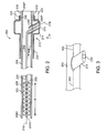
- FIG. 2 is a partially cutaway delivery system for deploying a stent in accordance with one embodiment of the present invention
- FIG. 3 is an enlarged bottom perspective view of a sheath and a keel of the delivery system of FIG. 2;
- FIG. 4 is a partially cutaway view of the delivery system taken from the bottom along a line IV of FIG. 2 after deployment of the stent;
- FIG. 5 is a partially cutaway delivery system for deploying a self-expanding stent in accordance with another embodiment of the present invention
- FIG. 6 is a partially cutaway delivery system for deploying a self-expanding stent in accordance with yet another embodiment of the present invention.
- FIG. 7 is a cross-sectional view of a ratchet mechanism of the delivery system of FIG. 6.
- FIG. 8 is a partially cutaway delivery system for deploying a self-expanding stent in accordance with another embodiment of the present invention.
- a stent delivery system 200 includes a keel 216.
- Keel 216 is used to pass a pushrod 204 and a guidewire 218 into a sheath 206 through the tubular sidewall of sheath 206, i.e., not through the lumen opening at proximal end 206P of sheath 206. Accordingly, the entire length of travel of proximal end 206P of sheath 206 during deployment of a stent 202 is not required to be inside of handle 212, allowing handle 212 to be short. Since handle 212 is short, handle 212 is easy to manipulate.
- FIG. 2 is a partially cutaway delivery system 200 for deploying a self-expanding stent 202 in accordance with one embodiment of the present invention.
- Stent 202 is a radially self-expanding stent having a linear length X, e.g., 200 mm or more.
- Delivery system 200 includes a pushrod 204 and a sheath 206, sometimes called a catheter sheath.
- Pushrod 204 sometimes called an inner member or inner shaft, includes a distal end 204D and a proximal end 204P.
- the proximal end of a delivery system is referenced with respect to the operator's handle while the proximal end of a stent is referenced with respect to the end closest to the heart via the length of blood traveled from the heart.
- Stent 202 is placed over distal end 204D of pushrod 204.
- distal end 204D further includes radiopaque markers that allow the location of distal end 204D and stent 202 to be precisely tracked.
- Pushrod 204 includes a stop 208 or other structure to prevent stent 202 from being moved proximally during retraction of sheath 206 as discussed further below.
- Proximal end 204P of pushrod 204 terminates within and is mounted to a handle 212. More particularly, handle 212 includes a housing 214. Connected to, or integral with, housing 214 is a keel 216. Proximal end 204P of pushrod 204 is connected to keel 216 and thus to housing 214. Accordingly, pushrod 204 does not move relative to housing 214 of handle 212.
- pushrod 204 is a hollow tube and includes a guide wire lumen.
- a guide wire 218 extends through pushrod 204 and extends out distal end 204D of pushrod 204.
- Guide wire 218 further extends out of proximal end 204P of pushrod 204, through keel 216 and out of a guide wire port 220 of keel 216.
- pushrod 204 extends through keel 216 such that proximal end 204P of pushrod 204 is located at guide wire port 220 in this example.
- Sheath 206 includes a distal end 206D and a proximal end 206P. Prior to deployment, stent 202 is radially compressed and restrained within distal end 206D of sheath 206. Sheath 206 extends through handle 212 and out a sheath port 222 of handle 212. A sheath knob 224 is located on and attached to proximal end 206P of sheath 206.
- sheath knob 224 and housing 214 includes thread 226, 228, respectively, allowing sheath knob 224 to be screwed on to and mounted to housing 214.
- a sheath knob bearing 230 rotatably mounts sheath knob 224 to sheath 206 allowing sheath knob 224 to be unscrewed from housing 214 without rotation of sheath 206.
- Strain relief 232 Coupled to and extending distally from handle 212 is a strain relief 232. Strain relief 232 distributes the bending force over a longer length of the sheath than jus a point load at the end of the handle which may create kinking.
- FIG. 3 is an enlarged bottom perspective view of sheath 206 and keel 216 of delivery system 200 of FIG. 2.
- sheath 206 is a hollow tube formed of a tubular sidewall and includes a pushrod lumen.
- Keel 216 extends radially inward from the side of housing 214 and penetrates radially into sheath 206 through the tubular sidewall of sheath 206. Accordingly, keel 216 extends from outside of sheath 206, through the tubular sidewall of sheath 206, and into the pushrod lumen of sheath 206.
- sheath 206 is retracted. As sheath 206 is retracted, sheath 206 moves relative to keel 216. Keel 216, a rigid member, is thus forced against sheath 206 causing keel 216 to split sheath 206.
- sheath 206 includes a breakaway 302 distal to keel 216 and a slit 304 proximal to keel 316.
- breakaway 302 extends longitudinally along sheath 206, i.e., parallel to longitudinal axis L of sheath 206, distally from keel 316.
- breakaway 302 is a region of sheath 206 having less structural integrity than the remainder of sheath 206 such that sheath 206 preferentially splits, sometimes called breaks, at breakaway 302 upon contact with keel 216.
- breakaway 302 includes one or more perforations, scores, interlocking teeth, a zipper, a slit, or other feature that facilitates splitting of sheath 206 at breakaway 302.
- sheath 206 has elasticity sufficient to allow sheath 206 to be split and pulled around keel 216 without permanent deformation of sheath 206. Accordingly, sheath 206 returns to the cylindrical shape of sheath 206 after being split by keel 216.
- slit 304 e.g., a longitudinal cut in sheath 206, extends longitudinally proximally from keel 216.
- sheath 206 is a hollow tube and includes a pushrod lumen.
- Pushrod 204 extends through keel 216 and into sheath 206.
- stent 202 is placed over distal end 204D of pushrod 204 and is radially compressed and restrained within distal end 206D of sheath 206.
- Stent 202 is introduced intra-vascularly and guided to the treatment site, e.g., a stenosis or narrowing of the vascular vessel.
- sheath 206 is retracted by retraction of sheath knob 224.
- sheath knob 224 is unscrewed from housing 214.
- Sheath knob 224 is pulled from housing 214, e.g., by the physician, thus retracting sheath 206.
- Stent 202 is self-expandable and as sheath 206 is retracted, stent 202 self-expands as it is uncovered and is permanently deployed, e.g., anchored within a lumen of a patient.
- sheath 206 moves (is retracted) at least the entire length X of stent 202 to completely uncover and thus deploy stent 202. Since retraction of sheath 206 is accomplished by pulling of sheath 206 out of handle 212, handle 212 can be much shorter than stent 202.
- FIG. 4 is a partially cutaway view of delivery system 200 taken from the bottom along line IV of FIG. 2 after deployment of stent 202.
- sheath 206 moves (is retracted) at least the entire length X of stent 202 (see FIG. 2) to completely uncover and thus deploy stent 202.
- handle 212 has a linear length Y less than linear length X of stent 202.
- keel 216 is used to pass pushrod 204 and guidewire 218 into sheath 206 through the tubular sidewall of sheath 206, i.e., not through the pushrod lumen opening at proximal end 206P of sheath 206. Accordingly, the entire length of travel of proximal end 206P is not required to be inside of handle 212, allowing handle 212 to be short. Since handle 212 is short, handle 212 is easy to manipulate.
- FIG. 5 is a partially cutaway delivery system 500 for deploying a self-expanding stent in accordance with another embodiment of the present invention.
- Pushrod 204A, sheath 206A, handle 212A, housing 214A, guide wire 218A, guide wire port 220A, sheath port 222A, sheath knob 224A, threads 226A, 228A, bearing 230A, and strain relief 232A of delivery system 500 of FIG. 5 are similar to pushrod 204, sheath 206, handle 212, housing 214, guide wire 218, guide wire port 220, sheath port 222, sheath knob 224, threads 226, 228, bearing 230, and strain relief 232 of delivery system 200 of FIG. 2, respectively, and so are not discussed further.
- keel 216A is directly attached to (or integral with) proximal end 204P of pushrod 204A, for example, with adhesive, welding, threads, or mechanical fasteners.
- keel 216A is an extension of pushrod 204A that passes from within sheath 206A, through the cylindrical, sometimes called tubular, sidewall of sheath 206A, and to housing 214A of handle 212A. In one example, as indicated by the dashed line, keel 216A protrudes outside from housing 214A.
- Guide wire 218A passes through guide wire port 220A and into keel 216A, passes through keel 216A and into sheath 206A, and from keel 216A passes into pushrod 204A.
- Use of keel 216A allows handle 212A to be short and easy to manipulate.
- FIG. 6 is a partially cutaway delivery system 600 for deploying a self-expanding stent in accordance with yet another embodiment of the present invention.
- Pushrod 204B, sheath 206B, handle 212B, housing 214B, guide wire 218B, guide wire port 220B, sheath port 222B, strain relief 232B, breakaway 302B, and slit 304B of delivery system 600 of FIG. 6 are similar to pushrod 204, sheath 206, handle 212, housing 214, guide wire 218, guide wire port 220, sheath port 222, strain relief 232, breakaway 302, and slit 304 of delivery system 200 of FIGS. 2 and 3, respectively, and so are not discussed further.
- keel 216B extends distally from the rear of housing 214B and penetrates into sheath 206B.
- pushrod 204B extends straight through handle 212B and without any significant bending.
- sheath 206 extends straight through handle 212 and pushrod 204 bends radially outward to extend through both keel 216 and the tubular sidewall of sheath 206 to the side of housing 214.
- sheath 206B is bent radially outwardly to extend out the side of housing 214B through sheath port 222B. Further, in accordance with this example, sheath 206B is retracted by use of a ratchet mechanism 702.
- FIG. 7 is a cross-sectional view of ratchet mechanism 702 of delivery system 600 of FIG. 6.
- ratchet mechanism 702 includes a thumb slider 704 slidably attached to housing 214B.
- thumb slider 704 retracts, i.e., moves proximally, thumb slider 704 to retract sheath 206B.
- thumb slider 704 is fully retracted, i.e., moved proximally to the end of travel of thumb slider 704 such that thumb slider 704 is in abutting contact with housing 214B
- thumb slider 704 is advanced, i.e., moved distally.
- sheath 206B is engaged with housing 214B such that thumb slider 704 is advanced without advancement of sheath 206B. This procedure is continuously repeated to retract sheath 206B to deploy the stent.
- sheath 206B feeds out of sheath port 222B.
- sheath 206B includes teeth 706.
- thumb slider 704 includes teeth 708 and housing 214B includes teeth 710.
- Teeth 706 of sheath 206B slide only proximally relative to teeth 708, 710 of thumb slider 704 and housing 214B, respectively.
- teeth 706 of sheath 206B do not slide distally relative to teeth 708, 710 of thumb slider 704 and housing 214B, respectively. This facilitates one-way proximal motion of sheath 206B, i.e., retraction of sheath 206, relative to thumb slider 704 and housing 214B as set forth in greater detail below.
- a first tooth 706A of teeth 706 of sheath 206B includes an engagement surface 712 and a sliding surface 714.
- Engagement surface 712 is distal to sliding surface 714. Further, engagement surface 712 is radially perpendicular to longitudinal axis L of sheath 206B. Conversely, sliding surface 714 extends from engagement surface 712 proximally inward and at an angle to engagement surface 712.
- a first tooth 708A of teeth 708 of thumb slider 704 includes an engagement surface 716 and a sliding surface 718.
- Engagement surface 716 is proximal to sliding surface 718. Further, engagement surface 716 is radially perpendicular to longitudinal axis L of sheath 206B. Conversely, sliding surface 718 extends from engagement surface 712 distally outward and at an angle to engagement surface 716.
- a first tooth 710A of teeth 710 of housing 214B includes an engagement surface 720 and a sliding surface 722.
- Engagement surface 720 is proximal to sliding surface 722. Further, engagement surface 720 is radially perpendicular to longitudinal axis L of sheath 206B. Conversely, sliding surface 722 extends from engagement surface 720 distally outward and at an angle to engagement surface 720.
- thumb slider 704 causes engagement surfaces 716 of teeth 708 of thumb slider 704 to engage engagement surfaces 712 of teeth 706 of sheath 206B. Accordingly, retraction of thumb slider 704 causes retraction of sheath 206B. As sheath 206B is retracted, slider surfaces 714 of teeth 706 of sheath 206B slide against slider surfaces 722 of teeth 710 of housing 214B. Stated another way, as sheath 206B is retracted, teeth 706 of sheath 206B slide past teeth 710 of housing 214B.
- thumb slider 704 Once thumb slider 704 reaches the end of its proximal travel, thumb slider 704 is advanced, i.e., moved distally. However, engagement surfaces 712 of teeth 706 of sheath 206B engage engagement surfaces 720 of teeth 710 of housing 214B preventing advancement of sheath 206B relative to housing 214B. Further, as thumb slider 704 is advanced, slider surfaces 718 of teeth 708 of thumb slider 704 slide against slider surfaces 714 of teeth 706 of sheath 206B. Stated another way, as thumb slider 704 is advanced, teeth 708 of thumb slider 704 slide past teeth 706 of sheath 206B. Referring again to FIG. 6, use of keel 216B and ratchet mechanism 702 allows handle 212B to be short and easy to manipulate.
- FIG. 8 is a partially cutaway delivery system 800 for deploying a self-expanding stent in accordance with another embodiment of the present invention.
- Pushrod 204C, sheath 206C, handle 212C, housing 214C, guide wire 218C, guide wire port 220C, strain relief 232C, breakaway 302C, and slit 304C of delivery system 800 of FIG. 8 are similar to pushrod 204B, sheath 206B (absent teeth 706), handle 212B, housing 214B, guide wire 218B, guide wire port 220B, strain relief 232B, breakaway 302B, and slit 304B of delivery system 600 of FIG. 6, respectively, and so are not discussed further.
- handle 212C includes a spool 802 coupled to housing 214C. More particularly, spool 802 rotates on an axle 804 extending through spool 802 and coupled to housing 214C.
- Proximal end 206P of sheath 206C is connected to spool 802.
- Spool 802 sometimes called a coil, provides a means for retracting sheath 206C.
- spool 802 includes a spool knob 806 that is rotated by the physician thus rotating spool 802 around axle 804. As spool 802 rotates, sheath 206C is wound into spool 802 and thus retracted.
- handle 212C By winding (coiling) sheath 206C around spool 802, handle 212C can be much shorter than the length of the stent. Since handle 212C is short, handle 212C is easy to manipulate.
- a method of delivering a stent includes restraining the stent within a distal end of a sheath; passing a keel into the sheath through a tubular sidewall of the sheath; retracting the sheath causing the sheath to be forced against the keel, whereby the keel splits the sheath.
- retraction of the sheath uncovers the stent.
- the stent typically self-expands as the stent is uncovered.
- the stent is located near a distal end of a pushrod, wherein the pushrod has a proximal end connected to the keel.
Landscapes
- Health & Medical Sciences (AREA)
- Engineering & Computer Science (AREA)
- Biomedical Technology (AREA)
- Cardiology (AREA)
- Oral & Maxillofacial Surgery (AREA)
- Transplantation (AREA)
- Heart & Thoracic Surgery (AREA)
- Vascular Medicine (AREA)
- Life Sciences & Earth Sciences (AREA)
- Animal Behavior & Ethology (AREA)
- General Health & Medical Sciences (AREA)
- Public Health (AREA)
- Veterinary Medicine (AREA)
- Media Introduction/Drainage Providing Device (AREA)
Applications Claiming Priority (1)
| Application Number | Priority Date | Filing Date | Title |
|---|---|---|---|
| US11/279,599 US9211206B2 (en) | 2006-04-13 | 2006-04-13 | Short handle for a long stent |
Publications (1)
| Publication Number | Publication Date |
|---|---|
| EP1844739A1 true EP1844739A1 (fr) | 2007-10-17 |
Family
ID=38255404
Family Applications (1)
| Application Number | Title | Priority Date | Filing Date |
|---|---|---|---|
| EP07007610A Withdrawn EP1844739A1 (fr) | 2006-04-13 | 2007-04-13 | Poignée courte pour une endoprothèse longue |
Country Status (3)
| Country | Link |
|---|---|
| US (1) | US9211206B2 (fr) |
| EP (1) | EP1844739A1 (fr) |
| JP (1) | JP2007283113A (fr) |
Cited By (16)
| Publication number | Priority date | Publication date | Assignee | Title |
|---|---|---|---|---|
| EP2111826A1 (fr) * | 2008-04-26 | 2009-10-28 | Biotronik VI Patent AG | Dispositif d'introduction avec un dispositif de libération pour la libération d'un objet supporté par un cathéter et dispositif de libération d'un dispositif d'introduction |
| WO2010120670A1 (fr) * | 2009-04-15 | 2010-10-21 | Cook Incorporated | Appareil d'introduction |
| WO2010120671A1 (fr) * | 2009-04-15 | 2010-10-21 | Cook Incorporated | Système et poignée à déploiement réversible |
| WO2011034754A3 (fr) * | 2009-09-17 | 2011-06-03 | Conceptus, Inc. | Dispositifs et méthodes d'administration à effraction minimale |
| EP2522315A1 (fr) * | 2011-05-11 | 2012-11-14 | Cook Medical Technologies LLC | Dispositif d'administration actionné par rotation |
| US8414635B2 (en) | 1999-02-01 | 2013-04-09 | Idev Technologies, Inc. | Plain woven stents |
| US8419788B2 (en) | 2006-10-22 | 2013-04-16 | Idev Technologies, Inc. | Secured strand end devices |
| WO2014067787A1 (fr) * | 2012-10-30 | 2014-05-08 | Angiomed Gmbh & Co. Medizintechnik Kg | Système d'administration à cathéter pour la libération d'un implant auto-dilatable |
| EP2749258A1 (fr) * | 2012-12-28 | 2014-07-02 | Cook Medical Technologies LLC | Introducteur de prothèse endoluminale |
| US8821510B2 (en) | 2009-04-15 | 2014-09-02 | Cook Medical Technologies Llc | Flexible sheath with polymer coil |
| US8876881B2 (en) | 2006-10-22 | 2014-11-04 | Idev Technologies, Inc. | Devices for stent advancement |
| US9023095B2 (en) | 2010-05-27 | 2015-05-05 | Idev Technologies, Inc. | Stent delivery system with pusher assembly |
| EP2910221A1 (fr) | 2014-02-25 | 2015-08-26 | Biotronik AG | Dispositif de dégagement pour libérer un implant médical d'un cathéter ainsi que cathéter avec dispositif de dégagement |
| WO2016094068A1 (fr) * | 2014-12-09 | 2016-06-16 | Cook Medical Technologies Llc | Poignée à deux broches |
| WO2020168117A1 (fr) * | 2019-02-13 | 2020-08-20 | Boston Scientific Scimed, Inc. | Systèmes d'implantation d'endoprothèse |
| EP4034033B1 (fr) * | 2019-09-25 | 2024-10-02 | Aquedeon Medical, Inc. | Greffons vasculaire et aortique et outils de déploiement |
Families Citing this family (40)
| Publication number | Priority date | Publication date | Assignee | Title |
|---|---|---|---|---|
| US6261316B1 (en) | 1999-03-11 | 2001-07-17 | Endologix, Inc. | Single puncture bifurcation graft deployment system |
| US8034100B2 (en) | 1999-03-11 | 2011-10-11 | Endologix, Inc. | Graft deployment system |
| US20050021123A1 (en) | 2001-04-30 | 2005-01-27 | Jurgen Dorn | Variable speed self-expanding stent delivery system and luer locking connector |
| KR20010078965A (ko) * | 2001-05-26 | 2001-08-22 | 김영수 | 운송체에 대한 이동식 안전 구조물 |
| US20050273151A1 (en) * | 2004-06-04 | 2005-12-08 | John Fulkerson | Stent delivery system |
| DE602006012687D1 (de) | 2005-08-17 | 2010-04-15 | Bard Inc C R | Stentabgabesystem mit variabler geschwindigkeit |
| US11026822B2 (en) | 2006-01-13 | 2021-06-08 | C. R. Bard, Inc. | Stent delivery system |
| JP5345856B2 (ja) | 2006-01-13 | 2013-11-20 | シー・アール・バード・インコーポレーテッド | ステント搬送システム |
| GB0615658D0 (en) | 2006-08-07 | 2006-09-13 | Angiomed Ag | Hand-held actuator device |
| GB0713497D0 (en) | 2007-07-11 | 2007-08-22 | Angiomed Ag | Device for catheter sheath retraction |
| US20090093873A1 (en) * | 2007-09-28 | 2009-04-09 | The Cleveland Clinic Foundation | Vascular graft and method of use |
| US8075607B2 (en) * | 2007-12-27 | 2011-12-13 | Cook Medical Technologies Llc | Control handle |
| US8221494B2 (en) | 2008-02-22 | 2012-07-17 | Endologix, Inc. | Apparatus and method of placement of a graft or graft system |
| US8236040B2 (en) | 2008-04-11 | 2012-08-07 | Endologix, Inc. | Bifurcated graft deployment systems and methods |
| US9750625B2 (en) | 2008-06-11 | 2017-09-05 | C.R. Bard, Inc. | Catheter delivery device |
| GB0810749D0 (en) | 2008-06-11 | 2008-07-16 | Angiomed Ag | Catherter delivery device |
| EP2520320B1 (fr) | 2008-07-01 | 2016-11-02 | Endologix, Inc. | Systèmes de cathéter |
| JP5629871B2 (ja) | 2009-04-28 | 2014-11-26 | エンドロジックス、インク | 移植片あるいは移植片システムを配置する装置および方法 |
| EP2329799A1 (fr) * | 2009-12-07 | 2011-06-08 | Biotronik VI Patent AG | Système de cathéter avec dispositif de coupage pour la gaine du cathéter |
| GB201017834D0 (en) | 2010-10-21 | 2010-12-01 | Angiomed Ag | System to deliver a bodily implant |
| EP2635241B1 (fr) | 2010-11-02 | 2019-02-20 | Endologix, Inc. | Appareil de disposition de greffe ou de système de greffe |
| US8657866B2 (en) * | 2010-12-22 | 2014-02-25 | Cook Medical Technologies Llc | Emergency vascular repair prosthesis deployment system |
| CN103561807B (zh) | 2011-03-01 | 2015-11-25 | 恩朵罗杰克斯股份有限公司 | 导管系统及其使用方法 |
| US10213329B2 (en) | 2011-08-12 | 2019-02-26 | W. L. Gore & Associates, Inc. | Evertable sheath devices, systems, and methods |
| US9687372B2 (en) | 2012-10-17 | 2017-06-27 | C.R. Bard, Inc. | Hand unit to release a self-expanding implant |
| US9907641B2 (en) | 2014-01-10 | 2018-03-06 | W. L. Gore & Associates, Inc. | Implantable intraluminal device |
| US9763819B1 (en) | 2013-03-05 | 2017-09-19 | W. L. Gore & Associates, Inc. | Tapered sleeve |
| EP2991718B1 (fr) | 2013-05-03 | 2019-11-13 | C.R. Bard, Inc. | Gaine protectrice pouvant être pelée |
| US10966850B2 (en) * | 2014-03-06 | 2021-04-06 | W. L. Gore & Associates, Inc. | Implantable medical device constraint and deployment apparatus |
| US9597213B2 (en) * | 2015-02-12 | 2017-03-21 | Abbott Cardiovascular Systems Inc. | Handle mechanism for actuating delivery catheter |
| CN111529126A (zh) | 2015-06-30 | 2020-08-14 | 恩朵罗杰克斯股份有限公司 | 用于将第一细长构件固定至第二细长构件的系统及方法 |
| US10556287B2 (en) | 2017-02-21 | 2020-02-11 | Abbott Cardiovascular Systems Inc. | Method for selectively pretinning a guidewire core |
| US10258492B2 (en) | 2017-03-03 | 2019-04-16 | Cook Medical Technologies Llc | Prosthesis delivery system with axially collapsible sheath |
| WO2018165542A1 (fr) * | 2017-03-10 | 2018-09-13 | The Cleveland Clinic Foundation | Système d'administration d'implant bifurqué |
| ES2960532T3 (es) | 2017-10-11 | 2024-03-05 | Gore & Ass | Aparato de restricción y despliegue de dispositivos médicos implantables |
| US11389627B1 (en) | 2018-10-02 | 2022-07-19 | Lutonix Inc. | Balloon protectors, balloon-catheter assemblies, and methods thereof |
| US11654038B2 (en) * | 2019-05-13 | 2023-05-23 | Cordis Us Corp. | Stent delivery catheter system with a helicoid hypotube |
| EP4069161A1 (fr) | 2020-01-27 | 2022-10-12 | Boston Scientific Scimed Inc. | Système de déploiement d'endoprothèse |
| WO2023130157A1 (fr) * | 2022-01-10 | 2023-07-13 | Jiffystent Pty Ltd | Appareil et procédés d'insertion de stent |
| KR102605179B1 (ko) * | 2023-03-30 | 2023-11-24 | 주식회사 에스앤지바이오텍 | 스텐트 전달 장치 |
Citations (4)
| Publication number | Priority date | Publication date | Assignee | Title |
|---|---|---|---|---|
| US5433723A (en) * | 1991-10-11 | 1995-07-18 | Angiomed Ag | Apparatus for widening a stenosis |
| US6599296B1 (en) * | 2001-07-27 | 2003-07-29 | Advanced Cardiovascular Systems, Inc. | Ratcheting handle for intraluminal catheter systems |
| US20060074477A1 (en) * | 2004-09-29 | 2006-04-06 | Medtronic Vascular, Inc. | Self-expanding stent delivery system |
| WO2007013902A2 (fr) * | 2005-06-20 | 2007-02-01 | Wilson-Cook Medical Inc. | Dispositif servant a introduire un stent par decollement non iteratif |
Family Cites Families (43)
| Publication number | Priority date | Publication date | Assignee | Title |
|---|---|---|---|---|
| US4744364A (en) * | 1987-02-17 | 1988-05-17 | Intravascular Surgical Instruments, Inc. | Device for sealing percutaneous puncture in a vessel |
| US4988356A (en) * | 1987-02-27 | 1991-01-29 | C. R. Bard, Inc. | Catheter and guidewire exchange system |
| EP0408245B1 (fr) * | 1989-07-13 | 1994-03-02 | American Medical Systems, Inc. | Dispositif d'introduction d'un dilatateur |
| CA2060067A1 (fr) * | 1991-01-28 | 1992-07-29 | Lilip Lau | Systeme de placement d'un extenseur |
| US5324269A (en) * | 1991-09-19 | 1994-06-28 | Baxter International Inc. | Fully exchangeable dual lumen over-the-wire dilatation catheter with rip seam |
| US5389087A (en) * | 1991-09-19 | 1995-02-14 | Baxter International Inc. | Fully exchangeable over-the-wire catheter with rip seam and gated side port |
| US5195978A (en) * | 1991-12-11 | 1993-03-23 | Baxter International Inc. | Rapid exchange over-the-wire catheter with breakaway feature |
| US5201757A (en) * | 1992-04-03 | 1993-04-13 | Schneider (Usa) Inc. | Medial region deployment of radially self-expanding stents |
| US5707376A (en) * | 1992-08-06 | 1998-01-13 | William Cook Europe A/S | Stent introducer and method of use |
| JPH08500757A (ja) * | 1992-12-30 | 1996-01-30 | シュナイダー・(ユーエスエイ)・インコーポレーテッド | 身体に移植可能なステントを展開する装置 |
| US5571168A (en) * | 1995-04-05 | 1996-11-05 | Scimed Lifesystems Inc | Pull back stent delivery system |
| WO1996037167A1 (fr) * | 1995-05-25 | 1996-11-28 | Raychem Corporation | Ensemble prothese endovasculaire |
| US5776096A (en) * | 1996-06-06 | 1998-07-07 | Hdc Corporation | Dual lumen vascular catheter with expanding side portal |
| US6077295A (en) * | 1996-07-15 | 2000-06-20 | Advanced Cardiovascular Systems, Inc. | Self-expanding stent delivery system |
| US6606515B1 (en) * | 1996-09-13 | 2003-08-12 | Scimed Life Systems, Inc. | Guide wire insertion and re-insertion tools and methods of use |
| US6254628B1 (en) * | 1996-12-09 | 2001-07-03 | Micro Therapeutics, Inc. | Intracranial stent |
| US5954764A (en) * | 1996-09-20 | 1999-09-21 | Parodi; Juan Carlos | Device for concurrently placing an endovascular expander with an endovascular prosthesis |
| US5968052A (en) * | 1996-11-27 | 1999-10-19 | Scimed Life Systems Inc. | Pull back stent delivery system with pistol grip retraction handle |
| US6004328A (en) * | 1997-06-19 | 1999-12-21 | Solar; Ronald J. | Radially expandable intraluminal stent and delivery catheter therefore and method of using the same |
| US6117140A (en) * | 1998-06-26 | 2000-09-12 | Scimed Life Systems, Inc. | Stent delivery device |
| US6120522A (en) * | 1998-08-27 | 2000-09-19 | Scimed Life Systems, Inc. | Self-expanding stent delivery catheter |
| WO2001058383A2 (fr) * | 2000-02-11 | 2001-08-16 | Novo Rps Ulc | Systeme de pose d'endoprothese et son procede d'utilisation |
| US6494846B1 (en) * | 2000-06-20 | 2002-12-17 | Wayne Margolis Family Partnership, Ltd. | Dual-mode catheter |
| US6527746B1 (en) * | 2000-08-03 | 2003-03-04 | Ev3, Inc. | Back-loading catheter |
| US8080048B2 (en) * | 2001-12-03 | 2011-12-20 | Xtent, Inc. | Stent delivery for bifurcated vessels |
| US7182779B2 (en) * | 2001-12-03 | 2007-02-27 | Xtent, Inc. | Apparatus and methods for positioning prostheses for deployment from a catheter |
| US6800065B2 (en) * | 2002-04-04 | 2004-10-05 | Medtronic Ave, Inc. | Catheter and guide wire exchange system |
| US6905477B2 (en) * | 2002-09-20 | 2005-06-14 | Medtronic Vascular, Inc. | Catheter with improved transition section |
| US6893417B2 (en) * | 2002-09-20 | 2005-05-17 | Medtronic Vascular, Inc. | Catheter and guide wire exchange system with improved proximal shaft and transition section |
| US20040059369A1 (en) * | 2002-09-20 | 2004-03-25 | Niall Duffy | Catheter and guide wire exchange system |
| EP1445001B1 (fr) * | 2003-02-07 | 2006-11-22 | Pierpont Family Limited Partnership | Système de catheter pour angioplastie |
| JP4584832B2 (ja) * | 2003-05-23 | 2010-11-24 | 株式会社 京都医療設計 | ステント供給装置 |
| WO2005013855A2 (fr) * | 2003-08-01 | 2005-02-17 | Cook Urological, Incorporated | Dispositif de mise en place d'un implant |
| US7402141B2 (en) * | 2003-08-27 | 2008-07-22 | Heuser Richard R | Catheter guidewire system using concentric wires |
| US7276045B2 (en) * | 2003-11-24 | 2007-10-02 | Medtronic Vascular, Inc. | Apparatus and method for wire exchange |
| US20070156225A1 (en) * | 2003-12-23 | 2007-07-05 | Xtent, Inc. | Automated control mechanisms and methods for custom length stent apparatus |
| US7326236B2 (en) * | 2003-12-23 | 2008-02-05 | Xtent, Inc. | Devices and methods for controlling and indicating the length of an interventional element |
| US20050209582A1 (en) * | 2004-03-22 | 2005-09-22 | Medtronic Vascular, Inc. | Multi-lumen catheter system |
| US7323006B2 (en) * | 2004-03-30 | 2008-01-29 | Xtent, Inc. | Rapid exchange interventional devices and methods |
| EP1740133A2 (fr) * | 2004-04-28 | 2007-01-10 | AMS Research Corporation | Dispositifs medicaux d'administration endoscopique |
| US20050256562A1 (en) * | 2004-05-14 | 2005-11-17 | Boston Scientific Scimed, Inc. | Stent delivery handle and assembly formed therewith |
| EP1771221B1 (fr) * | 2004-07-29 | 2010-09-22 | Wilson-Cook Medical Inc. | Cathéter equipé d'un arbre à paroi divisible |
| US8029481B2 (en) * | 2006-10-17 | 2011-10-04 | Matthew Dickson Reavill | Apparatus and method of inserting an infusing catheter and determining catheter depth without a guidewire or direct contact with the catheter |
-
2006
- 2006-04-13 US US11/279,599 patent/US9211206B2/en active Active
-
2007
- 2007-04-13 JP JP2007129832A patent/JP2007283113A/ja active Pending
- 2007-04-13 EP EP07007610A patent/EP1844739A1/fr not_active Withdrawn
Patent Citations (4)
| Publication number | Priority date | Publication date | Assignee | Title |
|---|---|---|---|---|
| US5433723A (en) * | 1991-10-11 | 1995-07-18 | Angiomed Ag | Apparatus for widening a stenosis |
| US6599296B1 (en) * | 2001-07-27 | 2003-07-29 | Advanced Cardiovascular Systems, Inc. | Ratcheting handle for intraluminal catheter systems |
| US20060074477A1 (en) * | 2004-09-29 | 2006-04-06 | Medtronic Vascular, Inc. | Self-expanding stent delivery system |
| WO2007013902A2 (fr) * | 2005-06-20 | 2007-02-01 | Wilson-Cook Medical Inc. | Dispositif servant a introduire un stent par decollement non iteratif |
Cited By (38)
| Publication number | Priority date | Publication date | Assignee | Title |
|---|---|---|---|---|
| US8414635B2 (en) | 1999-02-01 | 2013-04-09 | Idev Technologies, Inc. | Plain woven stents |
| US9925074B2 (en) | 1999-02-01 | 2018-03-27 | Board Of Regents, The University Of Texas System | Plain woven stents |
| US8974516B2 (en) | 1999-02-01 | 2015-03-10 | Board Of Regents, The University Of Texas System | Plain woven stents |
| US8876880B2 (en) | 1999-02-01 | 2014-11-04 | Board Of Regents, The University Of Texas System | Plain woven stents |
| US8876881B2 (en) | 2006-10-22 | 2014-11-04 | Idev Technologies, Inc. | Devices for stent advancement |
| US8966733B2 (en) | 2006-10-22 | 2015-03-03 | Idev Technologies, Inc. | Secured strand end devices |
| US8419788B2 (en) | 2006-10-22 | 2013-04-16 | Idev Technologies, Inc. | Secured strand end devices |
| US9629736B2 (en) | 2006-10-22 | 2017-04-25 | Idev Technologies, Inc. | Secured strand end devices |
| US8739382B2 (en) | 2006-10-22 | 2014-06-03 | Idev Technologies, Inc. | Secured strand end devices |
| US9585776B2 (en) | 2006-10-22 | 2017-03-07 | Idev Technologies, Inc. | Secured strand end devices |
| US9895242B2 (en) | 2006-10-22 | 2018-02-20 | Idev Technologies, Inc. | Secured strand end devices |
| US9408730B2 (en) | 2006-10-22 | 2016-08-09 | Idev Technologies, Inc. | Secured strand end devices |
| US9408729B2 (en) | 2006-10-22 | 2016-08-09 | Idev Technologies, Inc. | Secured strand end devices |
| US9149374B2 (en) | 2006-10-22 | 2015-10-06 | Idev Technologies, Inc. | Methods for manufacturing secured strand end devices |
| US10470902B2 (en) | 2006-10-22 | 2019-11-12 | Idev Technologies, Inc. | Secured strand end devices |
| US8778006B2 (en) | 2008-04-26 | 2014-07-15 | Biotronik Vi Patent Ag | Delivery system having a release mechanism for releasing an object carried by a catheter as well as a release mechanism of a delivery system |
| EP2111826A1 (fr) * | 2008-04-26 | 2009-10-28 | Biotronik VI Patent AG | Dispositif d'introduction avec un dispositif de libération pour la libération d'un objet supporté par un cathéter et dispositif de libération d'un dispositif d'introduction |
| WO2010120671A1 (fr) * | 2009-04-15 | 2010-10-21 | Cook Incorporated | Système et poignée à déploiement réversible |
| US8968381B2 (en) | 2009-04-15 | 2015-03-03 | Cook Medical Technologies Llc | Everting deployment system and handle |
| US9326874B2 (en) | 2009-04-15 | 2016-05-03 | Cook Medical Technologies Llc | Introducer apparatus |
| WO2010120670A1 (fr) * | 2009-04-15 | 2010-10-21 | Cook Incorporated | Appareil d'introduction |
| US9820878B2 (en) | 2009-04-15 | 2017-11-21 | Cook Medical Technologies Llc | Everting deployment system and handle |
| US8821510B2 (en) | 2009-04-15 | 2014-09-02 | Cook Medical Technologies Llc | Flexible sheath with polymer coil |
| WO2011034754A3 (fr) * | 2009-09-17 | 2011-06-03 | Conceptus, Inc. | Dispositifs et méthodes d'administration à effraction minimale |
| US9023095B2 (en) | 2010-05-27 | 2015-05-05 | Idev Technologies, Inc. | Stent delivery system with pusher assembly |
| EP2522315A1 (fr) * | 2011-05-11 | 2012-11-14 | Cook Medical Technologies LLC | Dispositif d'administration actionné par rotation |
| WO2014067787A1 (fr) * | 2012-10-30 | 2014-05-08 | Angiomed Gmbh & Co. Medizintechnik Kg | Système d'administration à cathéter pour la libération d'un implant auto-dilatable |
| EP2749258A1 (fr) * | 2012-12-28 | 2014-07-02 | Cook Medical Technologies LLC | Introducteur de prothèse endoluminale |
| US9849015B2 (en) | 2012-12-28 | 2017-12-26 | Cook Medical Technologies Llc | Endoluminal prosthesis introducer |
| EP3078354A1 (fr) * | 2012-12-28 | 2016-10-12 | Cook Medical Technologies LLC | Introducteur de prothèse endoluminale |
| US10299949B2 (en) | 2014-02-25 | 2019-05-28 | Biotronik Ag | Release device for releasing a medical implant from a catheter, and catheter |
| EP2910221A1 (fr) | 2014-02-25 | 2015-08-26 | Biotronik AG | Dispositif de dégagement pour libérer un implant médical d'un cathéter ainsi que cathéter avec dispositif de dégagement |
| WO2016094068A1 (fr) * | 2014-12-09 | 2016-06-16 | Cook Medical Technologies Llc | Poignée à deux broches |
| US10137020B2 (en) | 2014-12-09 | 2018-11-27 | Cook Medical Technologies Llc | Two pronged handle |
| WO2020168117A1 (fr) * | 2019-02-13 | 2020-08-20 | Boston Scientific Scimed, Inc. | Systèmes d'implantation d'endoprothèse |
| US11602447B2 (en) | 2019-02-13 | 2023-03-14 | Boston Scientific Scimed Inc. | Stent delivery systems |
| US12144752B2 (en) | 2019-02-13 | 2024-11-19 | Boston Scientific Scimed, Inc. | Stent delivery systems |
| EP4034033B1 (fr) * | 2019-09-25 | 2024-10-02 | Aquedeon Medical, Inc. | Greffons vasculaire et aortique et outils de déploiement |
Also Published As
| Publication number | Publication date |
|---|---|
| US20070244540A1 (en) | 2007-10-18 |
| US9211206B2 (en) | 2015-12-15 |
| JP2007283113A (ja) | 2007-11-01 |
Similar Documents
| Publication | Publication Date | Title |
|---|---|---|
| EP1844739A1 (fr) | Poignée courte pour une endoprothèse longue | |
| EP1834610A1 (fr) | Manipulation pour une longue endoprothèse vasculaire auto-étendue | |
| US11026821B2 (en) | Device for catheter sheath retraction | |
| JP5748163B2 (ja) | 迅速交換機能を備えたステント送出カテーテル | |
| US10898360B2 (en) | Low profile stepped delivery system | |
| US5702418A (en) | Stent delivery system | |
| US6248100B1 (en) | Drainage catheter delivery system | |
| US8092468B2 (en) | Deployment handle for an implant deployment device | |
| US20090030495A1 (en) | System for controlled prosthesis deployment | |
| EP3284446A1 (fr) | Ensemble de poignée de dispositif de livraison pour le déploiement séquentiel d'une prothèse | |
| EP1844738A1 (fr) | Mécanisme pour assurer la mise en place d'endoprothèse rénale ostiale | |
| IL170698A (en) | System for delivering a medical device to a body location | |
| EP3040058A1 (fr) | Poignée de déploiement pour un dispositif d'administration pourvu d'un mécanisme à libération rapide d'une prothèse et re-gainage de la pointe du dispositif | |
| EP2736580B1 (fr) | Système de pose d'endoprothèse à échange rapide | |
| US20240268979A1 (en) | Bifurcated stents and delivery systems for deployment thereof |
Legal Events
| Date | Code | Title | Description |
|---|---|---|---|
| PUAI | Public reference made under article 153(3) epc to a published international application that has entered the european phase |
Free format text: ORIGINAL CODE: 0009012 |
|
| AK | Designated contracting states |
Kind code of ref document: A1 Designated state(s): AT BE BG CH CY CZ DE DK EE ES FI FR GB GR HU IE IS IT LI LT LU LV MC MT NL PL PT RO SE SI SK TR |
|
| AX | Request for extension of the european patent |
Extension state: AL BA HR MK YU |
|
| 17P | Request for examination filed |
Effective date: 20080417 |
|
| 17Q | First examination report despatched |
Effective date: 20080528 |
|
| AKX | Designation fees paid |
Designated state(s): DE ES FR GB IE IT |
|
| STAA | Information on the status of an ep patent application or granted ep patent |
Free format text: STATUS: THE APPLICATION IS DEEMED TO BE WITHDRAWN |
|
| 18D | Application deemed to be withdrawn |
Effective date: 20091103 |