EP1844751A2 - Dispositif de sortie pour sauna - Google Patents
Dispositif de sortie pour sauna Download PDFInfo
- Publication number
- EP1844751A2 EP1844751A2 EP07010587A EP07010587A EP1844751A2 EP 1844751 A2 EP1844751 A2 EP 1844751A2 EP 07010587 A EP07010587 A EP 07010587A EP 07010587 A EP07010587 A EP 07010587A EP 1844751 A2 EP1844751 A2 EP 1844751A2
- Authority
- EP
- European Patent Office
- Prior art keywords
- steam
- outlet
- outlet device
- box
- air
- Prior art date
- Legal status (The legal status is an assumption and is not a legal conclusion. Google has not performed a legal analysis and makes no representation as to the accuracy of the status listed.)
- Withdrawn
Links
Images
Classifications
-
- A—HUMAN NECESSITIES
- A61—MEDICAL OR VETERINARY SCIENCE; HYGIENE
- A61H—PHYSICAL THERAPY APPARATUS, e.g. DEVICES FOR LOCATING OR STIMULATING REFLEX POINTS IN THE BODY; ARTIFICIAL RESPIRATION; MASSAGE; BATHING DEVICES FOR SPECIAL THERAPEUTIC OR HYGIENIC PURPOSES OR SPECIFIC PARTS OF THE BODY
- A61H33/00—Bathing devices for special therapeutic or hygienic purposes
- A61H33/06—Artificial hot-air or cold-air baths; Steam or gas baths or douches, e.g. sauna or Finnish baths
- A61H33/063—Heaters specifically designed therefor
-
- A—HUMAN NECESSITIES
- A61—MEDICAL OR VETERINARY SCIENCE; HYGIENE
- A61H—PHYSICAL THERAPY APPARATUS, e.g. DEVICES FOR LOCATING OR STIMULATING REFLEX POINTS IN THE BODY; ARTIFICIAL RESPIRATION; MASSAGE; BATHING DEVICES FOR SPECIAL THERAPEUTIC OR HYGIENIC PURPOSES OR SPECIFIC PARTS OF THE BODY
- A61H33/00—Bathing devices for special therapeutic or hygienic purposes
- A61H33/06—Artificial hot-air or cold-air baths; Steam or gas baths or douches, e.g. sauna or Finnish baths
- A61H33/10—Devices on tubs for steam baths
-
- A—HUMAN NECESSITIES
- A61—MEDICAL OR VETERINARY SCIENCE; HYGIENE
- A61H—PHYSICAL THERAPY APPARATUS, e.g. DEVICES FOR LOCATING OR STIMULATING REFLEX POINTS IN THE BODY; ARTIFICIAL RESPIRATION; MASSAGE; BATHING DEVICES FOR SPECIAL THERAPEUTIC OR HYGIENIC PURPOSES OR SPECIFIC PARTS OF THE BODY
- A61H33/00—Bathing devices for special therapeutic or hygienic purposes
- A61H33/06—Artificial hot-air or cold-air baths; Steam or gas baths or douches, e.g. sauna or Finnish baths
- A61H2033/068—Steam baths
Definitions
- the invention relates to a device by means of which steam and air can be introduced into a steam bath cabin or the like.
- the invention is based on the object, a device of the type mentioned in such a way and to improve that the visual impression for the user of the steam bath cabin is improved.
- the invention proposes a device with the features mentioned in claim 1. Further developments of the invention are the subject of dependent claims.
- the lines open into a box in front of the open front of the cover is arranged at a distance.
- the purpose of the cover is to prevent fluid emerging from a line end, either air or steam, from hitting a user directly.
- it has the purpose of visually covering the box. It can also serve as a baffle for the flows of steam and air. So the lines run out in this box, so only in the box There is even the possibility of mixing between steam and air.
- the surface of the cover is larger than the area of the front of the box, wherein the cover is mounted so that it covers the box on all edges in the projection.
- this gap may have a surface that is perpendicular to the surface of the wall in which the box is housed.
- the outlet end of the air supply line has an outlet nozzle.
- This outlet nozzle can advantageously be rotated about a horizontal and / or a vertical axis. This makes it possible to adjust the direction of the air entering the box and entering the room from there. This happens in particular regardless of the way in which the steam flows in.
- the steam supply ends over a large area. It may simply be a cut end of the supply line, so that a circular cross-section of this opening is present.
- the invention proposes that the outlet openings of both lines are arranged approximately at the same point and have approximately the same cross-section.
- the air supply line has at its end two outlet nozzles, which may preferably be adjustable independently of each other.
- the mentioned box may in particular be designed as a mounting box for hollow walls, so that it can be attached and fixed with a circumferential flange on the back or front of an opening in a cavity wall.
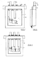
- FIG. 1 shows in an end view an outlet device for a steam bath cabin.
- the outlet device is arranged within a box 1 open on its front side.
- a supply line 2 for air which is bent at right angles at its end 3 and there has an outlet nozzle 4.
- the outlet nozzle can be rotated on the screw 5 about a vertical axis and in itself about a horizontal axis.
- the box is secured together with the tubes to a transverse square profile.
- the leads are screwed by means of flanges 9.
- the lines can also be attached directly to the box wall.
- the box 1 has on its outer side a circumferential right-angled flange 10, which serves for fastening in an opening of a cavity wall. This is evident, for example, from FIG. 2, which shows a side view of the device according to FIG. Here it can be seen that the flange 10 has a distance from the front edge of the box 1.
- FIG. 3 shows a slightly modified embodiment compared to FIG.
- two outlet nozzles 4 are arranged in the horizontally extending branch of the line one behind the other. Both outlet nozzles 4 are independently rotatable about the horizontal axis through the lower branch of the supply line 2 is formed.
- the outlet nozzles can also be adjusted by twisting the screw 5 about a vertical axis to a small extent.
- the outlet opening 14 of the first outlet nozzle 4 is in extension of the axis of the supply pipe 6 for steam.
- the outlet opening 14 of the second outlet nozzle 4 is correspondingly in extension of the second supply line 6 for steam. This ensures that the air actually forces the steam leaving the supply pipes in a certain direction.
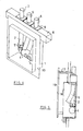
- Figure 4 shows the arrangement of Figure 3 perspective view in a simplified form.
- the glands of the flanges 9 are omitted for the sake of simplicity.
- This thus formed component which may be prefabricated, is then inserted into an opening of a cavity wall 15, see Figure 5.
- the flange 10 rests against the front of the cavity wall 15. But it is also conceivable to start from the back, depending on the circumstances of the case.
- cover plate 16 has a surface which is larger than the area of the front of the box 1. In the example shown, the cover 16 is offset slightly upwards. It is in any case ensured that, in an end view, the cover 16 completely covers the open front, so that there is no danger at any point that a jet of steam hits a user directly.
- the cover 16 can also take over optical functions. It can for example consist of glass. It can also be seen from FIG.
- the cover may additionally have slots, so that a part of the air-vapor mixture emerges to the front. These slots can be designed so that a meaningful distribution of leakage between on the one hand the front of the cover and on the other hand the lateral opening is achieved.
Landscapes
- Health & Medical Sciences (AREA)
- Public Health (AREA)
- Epidemiology (AREA)
- Pain & Pain Management (AREA)
- Physical Education & Sports Medicine (AREA)
- Rehabilitation Therapy (AREA)
- Life Sciences & Earth Sciences (AREA)
- Animal Behavior & Ethology (AREA)
- General Health & Medical Sciences (AREA)
- Veterinary Medicine (AREA)
- Devices For Medical Bathing And Washing (AREA)
- Production Of Liquid Hydrocarbon Mixture For Refining Petroleum (AREA)
- Hydrogen, Water And Hydrids (AREA)
- Cookers (AREA)
Applications Claiming Priority (2)
| Application Number | Priority Date | Filing Date | Title |
|---|---|---|---|
| DE102004006455A DE102004006455A1 (de) | 2004-02-05 | 2004-02-05 | Austrittseinrichtung für Dampfkabinen |
| EP05000101A EP1561447B1 (fr) | 2004-02-05 | 2005-01-05 | Dispositif de sortie pour une cabine a vapeur |
Related Parent Applications (1)
| Application Number | Title | Priority Date | Filing Date |
|---|---|---|---|
| EP05000101A Division EP1561447B1 (fr) | 2004-02-05 | 2005-01-05 | Dispositif de sortie pour une cabine a vapeur |
Publications (2)
| Publication Number | Publication Date |
|---|---|
| EP1844751A2 true EP1844751A2 (fr) | 2007-10-17 |
| EP1844751A3 EP1844751A3 (fr) | 2007-11-14 |
Family
ID=34673229
Family Applications (2)
| Application Number | Title | Priority Date | Filing Date |
|---|---|---|---|
| EP05000101A Expired - Lifetime EP1561447B1 (fr) | 2004-02-05 | 2005-01-05 | Dispositif de sortie pour une cabine a vapeur |
| EP07010587A Withdrawn EP1844751A3 (fr) | 2004-02-05 | 2005-01-05 | Dispositif de sortie pour sauna |
Family Applications Before (1)
| Application Number | Title | Priority Date | Filing Date |
|---|---|---|---|
| EP05000101A Expired - Lifetime EP1561447B1 (fr) | 2004-02-05 | 2005-01-05 | Dispositif de sortie pour une cabine a vapeur |
Country Status (4)
| Country | Link |
|---|---|
| EP (2) | EP1561447B1 (fr) |
| AT (1) | ATE363264T1 (fr) |
| DE (2) | DE102004006455A1 (fr) |
| ES (1) | ES2286718T3 (fr) |
Families Citing this family (1)
| Publication number | Priority date | Publication date | Assignee | Title |
|---|---|---|---|---|
| DE102010048402B4 (de) | 2010-10-13 | 2013-10-31 | Klafs Gmbh & Co. Kg | Austrittseinrichtung für ein Dampfbad und Dampfbad mit einer Austrittseinrichtung |
Family Cites Families (10)
| Publication number | Priority date | Publication date | Assignee | Title |
|---|---|---|---|---|
| DE3314617A1 (de) * | 1983-03-23 | 1984-10-04 | Condair AG, Münchenstein | Verfahren und vorrichtung zur beschickung einer dampfsaunakabine |
| DE8408077U1 (de) | 1983-03-31 | 1984-08-23 | Delco, Guido, Schönenberg | Vorrichtung zum erzeugen von dampf fuer eine dampfbad-kabine |
| DE3707643C2 (de) * | 1987-03-10 | 1997-06-05 | Kurz Rudolf Gmbh & Co | Mit einer Kabine, vorzugsweise einer Schwitz- oder Inhalierkabine zusammenwirkendes Gerät zum Erzeugen und Einleiten von Dampf in die Kabine |
| IT211945Z2 (it) * | 1987-07-24 | 1989-05-25 | Teuco Guzzini Srl | Sauna di vapore con un impianto vaporizzatore posta in una cupola applicata superiormente alla cabina. |
| JPH0373148A (ja) * | 1989-08-12 | 1991-03-28 | Matsushita Electric Works Ltd | スチームルーム |
| JPH05137771A (ja) * | 1991-11-18 | 1993-06-01 | Matsushita Electric Ind Co Ltd | 蒸気噴出装置 |
| FR2727499B1 (fr) * | 1994-11-28 | 1997-01-03 | Luc Jean Paul | Generateur pour bain de vapeur |
| DE29801194U1 (de) * | 1998-01-26 | 1998-04-02 | Meier, Hansjürgen, 32339 Espelkamp | In ein Dampfbad mündendes Dampfaustrittsrohr |
| DE20100427U1 (de) * | 2001-01-11 | 2001-03-29 | Hoesch Metall + Kunststoffwerk GmbH & Co, 52372 Kreuzau | Einrichtung zur Einspeisung von Dampf in eine Dampfbadekabine |
| DE10326942A1 (de) * | 2003-06-05 | 2004-12-30 | Hansgrohe Ag | Vorrichtung zum Dampfaustritt von einer Dampferzeugung ins Innere einer Dampfkabine |
-
2004
- 2004-02-05 DE DE102004006455A patent/DE102004006455A1/de not_active Withdrawn
-
2005
- 2005-01-05 EP EP05000101A patent/EP1561447B1/fr not_active Expired - Lifetime
- 2005-01-05 ES ES05000101T patent/ES2286718T3/es not_active Expired - Lifetime
- 2005-01-05 DE DE502005000754T patent/DE502005000754D1/de not_active Expired - Lifetime
- 2005-01-05 EP EP07010587A patent/EP1844751A3/fr not_active Withdrawn
- 2005-01-05 AT AT05000101T patent/ATE363264T1/de not_active IP Right Cessation
Also Published As
| Publication number | Publication date |
|---|---|
| EP1561447B1 (fr) | 2007-05-30 |
| ATE363264T1 (de) | 2007-06-15 |
| EP1561447A1 (fr) | 2005-08-10 |
| DE502005000754D1 (de) | 2007-07-12 |
| ES2286718T3 (es) | 2007-12-01 |
| EP1844751A3 (fr) | 2007-11-14 |
| DE102004006455A1 (de) | 2005-08-25 |
Similar Documents
| Publication | Publication Date | Title |
|---|---|---|
| DE102013004076B4 (de) | Strahlregler mit Prallfläche und Ringwandung | |
| DE102009057355B4 (de) | Lüftungseinrichtung zum Zuführen und/oder Abführen von Luft | |
| EP2971385A1 (fr) | Régulateur de jet pourvu d'une surface d'impact dotée de parois annulaires | |
| DE102006046245A1 (de) | Strahlregler | |
| EP2597213B1 (fr) | Composant sanitaire | |
| DE2609030B2 (de) | Verfahren und Vorrichtung zum Führen von aus einer luftdurchlässigen, insbesondere perforierten Fläche austretenden Luftströmen | |
| DE2851046A1 (de) | Luftauslassvorrichtung fuer raumklimatisierungs- und belueftungsanlagen | |
| DE102015101510A1 (de) | Fassadenanschlusseinrichtung für eine Lüftungseinrichtung sowie Lüftungseinrichtung | |
| EP1561447B1 (fr) | Dispositif de sortie pour une cabine a vapeur | |
| DE2325118C2 (de) | Klimatisierungsvorrichtung | |
| DE3727882A1 (de) | Verfahren zur klimatisierung von raeumen sowie klimatisierungssystem zur durchfuehrung des verfahrens | |
| DE202016100271U1 (de) | Schornsteinelement | |
| DE4244405C1 (de) | Entlueftungsvorrichtung | |
| DE29615925U1 (de) | Warmwasserbereiter | |
| DE102006062986B3 (de) | Sanitäre Auslaufarmatur mit einem Strahlregler | |
| DE102006062983B3 (de) | Strahlregler | |
| DE1679539C3 (de) | Verteilkanal für übersättigte Luft für eine Lüftungs- oder Klimaanlage | |
| DE2401801A1 (de) | Luftverteilervorrichtung | |
| AT207088B (de) | Abschirmung von Raumöffnungen durch einen Luftschleier | |
| DE19529311C1 (de) | Auslaßdüsenleiste und Verfahren zum räumlichen Verteilen eines strömenden Mediums | |
| EP3587943A2 (fr) | Dispositif d'aération et de mise en température d'une pièce dans un bâtiment | |
| AT239495B (de) | Vorrichtung zur Trockenlegung von Mauerwerk | |
| DE19912567A1 (de) | Luftleiteinrichtung für einen Luftdurchlaß | |
| DE102007052205B4 (de) | Luftauslassdüse für eine Trennstrahlanlage und Düsenstrang | |
| DE9209849U1 (de) | Befeuchtungseinrichtung für ein Verkaufsmöbel |
Legal Events
| Date | Code | Title | Description |
|---|---|---|---|
| PUAI | Public reference made under article 153(3) epc to a published international application that has entered the european phase |
Free format text: ORIGINAL CODE: 0009012 |
|
| PUAL | Search report despatched |
Free format text: ORIGINAL CODE: 0009013 |
|
| 17P | Request for examination filed |
Effective date: 20070619 |
|
| AC | Divisional application: reference to earlier application |
Ref document number: 1561447 Country of ref document: EP Kind code of ref document: P |
|
| AK | Designated contracting states |
Kind code of ref document: A2 Designated state(s): AT BE BG CH CY CZ DE DK EE ES FI FR GB GR HU IE IS IT LI LT LU MC NL PL PT RO SE SI SK TR |
|
| AK | Designated contracting states |
Kind code of ref document: A3 Designated state(s): AT BE BG CH CY CZ DE DK EE ES FI FR GB GR HU IE IS IT LI LT LU MC NL PL PT RO SE SI SK TR |
|
| RIC1 | Information provided on ipc code assigned before grant |
Ipc: A61H 33/06 20060101ALI20071011BHEP Ipc: A61H 33/10 20060101AFI20070910BHEP |
|
| 17Q | First examination report despatched |
Effective date: 20080328 |
|
| AKX | Designation fees paid |
Designated state(s): AT BE BG CH CY CZ DE DK EE ES FI FR GB GR HU IE IS IT LI LT LU MC NL PL PT RO SE SI SK TR |
|
| STAA | Information on the status of an ep patent application or granted ep patent |
Free format text: STATUS: THE APPLICATION IS DEEMED TO BE WITHDRAWN |
|
| 18D | Application deemed to be withdrawn |
Effective date: 20090804 |