EP1844960B1 - Machine pour monter et démonter un pneu équipé d'un anneau de roulage à plat interne rigide - Google Patents
Machine pour monter et démonter un pneu équipé d'un anneau de roulage à plat interne rigide Download PDFInfo
- Publication number
- EP1844960B1 EP1844960B1 EP07106201A EP07106201A EP1844960B1 EP 1844960 B1 EP1844960 B1 EP 1844960B1 EP 07106201 A EP07106201 A EP 07106201A EP 07106201 A EP07106201 A EP 07106201A EP 1844960 B1 EP1844960 B1 EP 1844960B1
- Authority
- EP
- European Patent Office
- Prior art keywords
- tyre
- axis
- tool
- tooling
- slide
- Prior art date
- Legal status (The legal status is an assumption and is not a legal conclusion. Google has not performed a legal analysis and makes no representation as to the accuracy of the status listed.)
- Not-in-force
Links
- 241001481828 Glyptocephalus cynoglossus Species 0.000 claims 1
- 239000011324 bead Substances 0.000 description 20
- 238000003780 insertion Methods 0.000 description 3
- 230000037431 insertion Effects 0.000 description 3
- 238000000605 extraction Methods 0.000 description 2
- 239000013536 elastomeric material Substances 0.000 description 1
- 239000002184 metal Substances 0.000 description 1
- 238000000034 method Methods 0.000 description 1
- 230000000284 resting effect Effects 0.000 description 1
Images

Classifications
-
- B—PERFORMING OPERATIONS; TRANSPORTING
- B60—VEHICLES IN GENERAL
- B60C—VEHICLE TYRES; TYRE INFLATION; TYRE CHANGING; CONNECTING VALVES TO INFLATABLE ELASTIC BODIES IN GENERAL; DEVICES OR ARRANGEMENTS RELATED TO TYRES
- B60C25/00—Apparatus or tools adapted for mounting, removing or inspecting tyres
- B60C25/01—Apparatus or tools adapted for mounting, removing or inspecting tyres for removing tyres from or mounting tyres on wheels
- B60C25/05—Machines
- B60C25/132—Machines for removing and mounting tyres
- B60C25/135—Machines for removing and mounting tyres having a tyre support or a tool, movable along wheel axis
- B60C25/138—Machines for removing and mounting tyres having a tyre support or a tool, movable along wheel axis with rotary motion of tool or tyre support
-
- B—PERFORMING OPERATIONS; TRANSPORTING
- B60—VEHICLES IN GENERAL
- B60C—VEHICLE TYRES; TYRE INFLATION; TYRE CHANGING; CONNECTING VALVES TO INFLATABLE ELASTIC BODIES IN GENERAL; DEVICES OR ARRANGEMENTS RELATED TO TYRES
- B60C25/00—Apparatus or tools adapted for mounting, removing or inspecting tyres
- B60C25/01—Apparatus or tools adapted for mounting, removing or inspecting tyres for removing tyres from or mounting tyres on wheels
- B60C25/05—Machines
- B60C25/0509—Machines for inserting additional parts, e.g. support rings, sensors
Definitions
- the present invention relates to a machine for assembling and disassembling a tyre fitted with a rigid inner run-flat ring.
- tyres of the above type are normally assembled and disassembled using special, relatively complex, high-cost powered devices completely separate from the tyre removing machines used two assemble and remove the tyre to and from the rim.
- US2004074610 discloses a method of fitting a tire and a removable tread support on a one-piece wheel rim, according to the preamble of claim 1.
- the rim comprises a first rim seat inclined outwards and a second rim seat and the tire comprises a first bead and a second bead to be mounted respectively on the first and second rim seats.
- EP0987130 discloses an auxiliary device for tyre removal machines, to enable them to correctly operate on wheels of special type having their wheel rim and tyre of asymmetric shape.
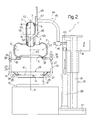
- Number 1 in Figure 2 indicates as a whole a machine - actually a conventional tyre removing machine - equipped with accessories for assembling and disassembling a conventional tyre 2 fitted with a known rigid inner run-flat ring 3.
- tyre 2 comprises two beads 4 and 5 defining the ends of a toroidal chamber 6.
- Rigid ring 3 is housed inside toroidal chamber 6, and comprises an undulated toroidal metal central portion 7, the maximum outside diameter of which is larger than the inside diameter of beads 4 and 5 and slightly larger than the maximum diameter of toroidal chamber 6 minus the maximum radial depth of toroidal chamber 6; and two beads 8 and 9 made of elastomeric material and of substantially the same inside diameter as beads 4 and 5.
- tyre removing machine 1 comprises a powered turntable 10 having a vertical axis 11 and, on top, a height-adjustable plate 12, which rotates about axis 11, supports a tub-shaped tool 13 with its concavity facing upwards, and has a known locating device 14 for engaging a bottom flange 15 of tub-shaped tool 13 to lock tub-shaped tool 13 radially in a position coaxial with axis 11 when tub-shaped tool 13 is placed on plate 12 with bottom flange 15 facing downwards.
- Tyre removing machine 1 also comprises a tool column 16 located alongside turntable 10 and in turn comprising a base 17, from which extends upwards a vertical prismatic guide 18 for a slide 19 moved along prismatic guide 18 by a single hydraulic or pneumatic jack 20 interposed between slide 19 and base 17.
- Slide 19 is fitted with a number of tools - not shown for the sake of simplicity - for assembling and disassembling a wheel (not shown) comprising tyre 2, relative rigid ring 3, and a relative rim (not shown).
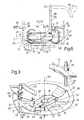
- tub-shaped tool 13 a tube 21 extends through bottom flange 15, is maintained, in use, coaxial with axis 11 by locating device 14, and is fitted with the facing ends of two coaxial, diametrically opposite sleeves 22 and 23 engaged by specular tubular members 24 and 25 respectively.
- Tubular members 24 and 25 are L-shaped, lie in a diametrical plane of axis 11 to define two supporting ribs of tub-shaped tool 13, and comprise respective bottom arms 26 perpendicular to axis 11 and coaxial with each other and with sleeves 22, 23; and respective top arms 27 parallel to each other and to axis 11, and located in said diametrical plane, on opposite sides of axis 11.
- bottom arm 26 of tubular member 24 is integral with sleeve 22, whereas bottom arm 26 of tubular member 25 engages sleeve 23 in sliding manner, and can be fixed selectively in any of a number of given axial positions with respect to sleeve 23, by means of a diametrical pin 28.
- top arms 27 support an annular rib 29 coaxial with axis 11 and lying in a plane perpendicular to axis 11.
- Annular rib 29 comprises a fixed portion 30, which is integral with tubular member 24, extends roughly 320° about axis 11, and is connected to bottom flange 15 by curved radial arms 31, and to sleeve 22 by a scoop 32; and a movable portion 33 movable radially with tubular member 25 and connected to a top end of a scoop 34, which is specular with respect to scoop 32 and has a bottom end resting on sleeve 23.
- a sleeve 36 is fixed, in an axially adjustable position, to top arm 27 of tubular member 24 by a removable radial pin 35, and is fitted with an annular segment-shaped plate 37 projecting, with respect to relative top arm 27, towards tubular member 25.
- a sleeve 39 is fixed, in an axially and angularly adjustable position, to top arm 27 of tubular member 25 by a removable radial pin 38, and is fitted with an annular segment-shaped plate 40 projecting, with respect to relative top arm 27, towards tubular member 24.
- Plates 37 and 40 are adjusted so as to be coplanar with a plane perpendicular to axis 11, and, whereas plate 37 is always oriented towards axis 11 with respect to relative top arm 27, plate 40 is adjustable about relative top arm 27 to selectively assume a first position ( Figure 3 ) facing tubular member 24, and a second position facing outwards of tub-shaped tool 13, a concave bottom surface 41 of which is defined by scoops 32 and 34, by radial arms 31, and by two curved ribs 42 located on opposite sides of the diametrical plane - coincident with the Figure 2 plane - defined by tubular members 24, 25 and extending upwards from bottom flange 15.
- slide 19 has a horizontal prismatic through guide (not shown) lying in said diametrical plane and engaged in sliding manner by a rod 43, which forms part of a removable accessory 44, can be fixed in any axial position to slide 19, and has an end portion projecting from slide 19 towards turntable 10.
- Accessory 44 also comprises an L-shaped bracket 45, one end of which is fitted with a transverse sleeve 46 fitted to the portion of rod 43 projecting from slide 19, and the other end of which is fitted with another transverse sleeve 47, which has an axis parallel to axis 11, lies in said diametrical plane, and is located over plate 12, on the same side of axis 11 as tool column 16.
- Accessory 44 also comprises a pressure tool 48, also located in said diametrical plane and in turn comprising a rod 49 fitted in an axially adjustable position through sleeve 47 and terminating, at the end facing plate 12, with a pad 50; and an appendix 51, also located in said diametrical plane, and which slopes downwards towards axis 11 from a portion of rod 49 just above pad 50, and terminates, at the end facing plate 12, with a pad 52 located on the opposite side of axis 11 to pad 50, and separated from pad 50 by a distance, measured crosswise to axis 11, greater than the distance between beads 8 and 9.
- a pressure tool 48 also located in said diametrical plane and in turn comprising a rod 49 fitted in an axially adjustable position through sleeve 47 and terminating, at the end facing plate 12, with a pad 50
- an appendix 51 also located in said diametrical plane, and which slopes downwards towards axis 11 from a portion of rod 49 just above pad 50, and terminate
- tub-shaped tool 13 is fixed to plate 12 with its concavity facing upwards, and with its own axis 53 ( Figure 2 ) coincident with axis 11; the height of sleeves 36 and 39 and the radial position of tubular member 25 are adjusted according to the size of tyre 2; plate 40 is locked angularly in the inner position, i.e. facing plate 37; and tyre 2 is placed flat on the support defined by plates 37 and 40, with its bead 5 facing downwards, and with its own axis 54 ( Figure 2 ) substantially coaxial with axis 11.
- rigid ring 3 whose outside diameter is only slightly greater than the inside diameter of beads 4 and 5, and whose thickness is less than the height of toroidal chamber 6, is placed on-edge on tyre 2, with central portion 7 contacting bead 4, and so that an equatorial plane 55 ( Figure 2 ) of rigid ring 3 contains axis 11, and an axis 56 ( Figure 2 ) of rigid ring 3 is parallel to rod 43.
- rod 43 is moved forward to insert appendix 51 inside rigid ring 3; and rod 49 is lowered, with respect to sleeve 47, to lower pad 52 onto the inner periphery of bead 8, and is then locked axially to sleeve 47.
- Jack 20 is then operated to move slide 19 down prismatic guide 18 and so insert rigid ring 3 on-edge inside tyre 2, by pressure tool 48 exerting thrust on rigid ring 3, and simultaneously deform beads 4 and 5.
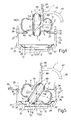
- This insertion stage is completed ( Figure 4 ) when axis 56 of rigid ring 3 lies on an equatorial plane 57 of the tyre.
- appendix 51 is extracted from rigid ring 3 by rotating rod 49 inside sleeve 47 and raising slide 19; plate 40 is locked angularly in the outer position ( Figure 5 ); and the tyre 2-rigid ring 3 assembly is placed on bottom surface 41 of tub-shaped tool 13, with tyre 2 tilted and laterally contacting scoop 32, and with rigid ring 3 tilted, laterally contacting ribs 42, and with its highest point positioned directly beneath pad 50.
- pad 50 acts on rigid ring 3 to rotate tyre 2 and rigid ring 3 in opposite directions ( Figure 5 ) on bottom surface 41 and about an instantaneous axis 58 perpendicular to the Figure 5 plane and substantially coincident with the intersection of equatorial planes 55 and 57, and so insert rigid ring 3 completely inside toroidal chamber 6 ( Figure 6 ).
- tyre 2 fitted completely with rigid ring 3, is laid flat inside, and can be extracted from, tub-shaped tool 13.
- tub-shaped tool 13 is fixed to plate 12 with its concavity facing upwards, and with its own axis 53 ( Figure 3 ) coincident with axis 11; the height of sleeves 36 and 39 and the radial position of tubular member 25 are adjusted according to the size of tyre 2; plate 40 is locked angularly in the inner position, i.e.
- tyre 2 is placed flat on the support defined by plates 37 and 40, with its bead 5 facing downwards, and with its own axis 54 ( Figure 1 ) substantially coaxial with axis 11; and rigid ring 3 is moved laterally, inside toroidal chamber 6, away from tool column 16, so that a portion of bead 8 is positioned radially inwards of the relative portion of bead 4 and directly accessible by pad 50.
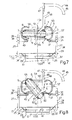
- rod 43 is moved forward to position pad 50 directly over said portion of bead 8; and rod 49 is lowered, with respect to sleeve 47, to lower pad 50 ( Figure 7 ) onto said portion of bead 8, and is then locked axially to sleeve 47.
- Jack 20 is then operated to move slide 19 down prismatic guide 18 ( Figure 8 ) and produce a simultaneous rotation-translation movement of rigid ring 3 about an instantaneous axis 59 perpendicular to the Figure 8 plane and substantially lying in equatorial plane 55, so that part of rigid ring 3 is extracted downwards from toroidal chamber 6.
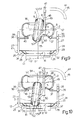
- the above rotation continues, by pressure tool 48 exerting thrust on rigid ring 3, until rigid ring 3 is positioned substantially on edge with respect to tyre 2 ( Figure 9 ).
- pad 50 is detached from bead 8 by raising slide 19 until pad 52 is positioned higher than the bottom portion of bead 9; rigid ring 3 is then manually rotated further by the operator to position central portion 7 of rigid ring 3 directly beneath pad 52; and slide 19 is lowered ( Figure 9 ) to bring pad 52 into direct contact with the inner surface of central portion 7 of rigid ring 3.
- tyre removing machine 1 As compared with known assembly and disassembly devices, are obvious, considering that, on tyre removing machine 1, rigid ring 3 is inserted and extracted using a power member - in this case, jack 20 - already provided on tyre removing machine 1 for other purposes, and by simply equipping tyre removing machine 1 with relatively low-cost, low-tech, compact, lightweight accessory tools - in this case, tub-shaped tool 13 and pressure tool 48.
Landscapes
- Engineering & Computer Science (AREA)
- Mechanical Engineering (AREA)
- Tires In General (AREA)
Claims (13)
- Outillage pouvant être fixé à une machine pour monter et démonter un pneu (2), ayant un anneau de roulage à plat, interne, rigide (3) situé à l'intérieur d'une chambre toroïdale (6) du pneu (2) ; la machine (1) étant une machine d'enlèvement de pneu et comprenant :un plateau tournant (10) ayant un axe (11) ;une colonne à outils (16) située le long du plateau tournant (10) et ayant un guide (18) parallèle audit axe (11) ;une coulisse (19) montée pour glisser le long du guide (18) ; etun moyen d'actionnement (20) pour déplacer la coulisse (19) le long du guide (18) ;l'outillage (1) entrant en interaction avec le pneu (2) et l'anneau de roulage à plat, interne, rigide (3) et étant caractérisé en ce qu'il comprend :un premier outil (13), qui peut être fixé au plateau tournant (10) pour supporter le pneu (2) et l'anneau rigide (3) et supporte le pneu (2) sur le plateau tournant (10) et à une distance donnée du plateau tournant (10) de manière que l'anneau rigide (3) puisse être agencé transversalement via un canal central du pneu (2) ; etun deuxième outil (48), qui peut être fixé à la coulisse (19) et est mobile avec la coulisse (19) le long de la colonne à outils (16) pour engager l'anneau rigide (3) et déplacer l'anneau rigide (3) par rapport au pneu (2) et via le canal central du pneu (2).
- Outillage selon la revendication 1, dans lequel le premier outil et le deuxième outil (13, 48) sont fixés, de manière amovible, respectivement au plateau tournant (10) et à la coulisse (19).
- Outillage selon la revendication 1 ou 2, dans lequel le premier outil (13) est un outil en forme de bac positionné sur le plateau tournant (10) coaxialement audit axe (11) et avec sa concavité tournée vers le haut ; le premier outil (13) recevant le pneu (2) posé à plat.
- Outillage selon l'une quelconque des revendications précédentes, dans lequel le premier outil (13) comprend des premier (41) et deuxièmes (37, 40) moyens de support pour supporter le pneu (2), posé à plat, dans des positions distinctes respectives le long dudit axe (11) ; les deuxièmes moyens de support (37, 40) étant situés au-dessus du premier moyen de support (41) le long dudit axe (11).
- Outillage selon la revendication 4, dans lequel les deuxièmes moyens de support (37, 40) sont sensiblement annulaires, et comprennent des première (37) et deuxième (40) plaques incurvées, coplanaires, transversalement audit axe (11), et diamétralement opposées par rapport audit axe (11).
- Outillage selon la revendication 5, dans lequel lesdites première et deuxième plaques (37, 40) sont réglables en hauteur par rapport au premier moyen de support (41).
- Outillage selon la revendication 5 ou 6, dans lequel ladite deuxième plaque (40) est mobile entre une position interne, dans laquelle la deuxième plaque (40) est située sur le premier moyen de support (41), et une position externe, dans laquelle la deuxième plaque (40) est déplacée de côté par rapport au premier moyen de support (41), pour permettre d'accéder par le pneu (2) au premier moyen de support (41).
- Outillage selon la revendication 3, ou l'une des revendications 4 à 7, dans lequel le premier moyen de support (41) est défini par une base du premier outil (13).
- Outillage selon l'une quelconque des revendications précédentes, dans lequel le deuxième outil (48) se situe dans un plan traversant ledit axe (11).
- Outillage selon l'une quelconque des revendications précédentes, dans lequel le deuxième outil (48) est un outil de pression comprenant un premier (50) et un deuxième (52) tampon, qui sont mobiles avec la coulisse (19) le long dudit axe (11), et engagent sélectivement l'anneau rigide (3) pour amener l'anneau rigide (3) à avoir un mouvement de translation le long dudit axe (11) par rapport au pneu (2), et pour tourner par rapport au pneu (2) autour d'un axe supplémentaire transversal audit axe (11).
- Outillage selon la revendication 10, dans lequel les premier et deuxième tampons (50, 52) sont situés sur des côtés opposés dudit axe (11), et sont décalés en hauteur, le premier tampon (50) étant situé au-dessus du deuxième tampon (52).
- Outillage selon la revendication 10 ou 11, dans lequel le deuxième outil (48) comprend une tige (49) parallèle audit axe (11) et reliée, dans une position réglable axialement, à la coulisse (19) ; la tige (49) ayant un appendice latéral incliné (51) traversant ledit axe (11) et s'étendant vers le plateau tournant (10) ; le premier tampon (50) étant supporté par la tige (49), et le deuxième tampon (52) étant supporté par l'appendice (51).
- Machine pour monter et démonter un pneu (2), ayant un anneau de roulage à plat, interne, rigide (3) situé à l'intérieur d'une chambre toroïdale (6) du pneu (2) ; la machine (1) étant une machine d'enlèvement de pneu et comprenant :un plateau tournant (10) ayant un axe (11) ;une colonne à outils (16) située le long du plateau tournant (10) et ayant un guide (18) parallèle audit axe (11) ;une coulisse (19) montée pour glisser le long du guide (18) ;un moyen d'actionnement (20) pour déplacer la coulisse (19) le long du guide (18) ; etun outillage selon l'une quelconque des revendications précédentes pour entrer en interaction avec le pneu (2) et l'anneau de roulage à plat, interne, rigide (3).
Applications Claiming Priority (1)
| Application Number | Priority Date | Filing Date | Title |
|---|---|---|---|
| IT000285A ITTO20060285A1 (it) | 2006-04-14 | 2006-04-14 | Macchina per l'assemblaggio e disassemblaggio di uno pneumatico provvisto di un anello rigido interno anti-appiattimento |
Publications (2)
| Publication Number | Publication Date |
|---|---|
| EP1844960A1 EP1844960A1 (fr) | 2007-10-17 |
| EP1844960B1 true EP1844960B1 (fr) | 2009-07-29 |
Family
ID=38267711
Family Applications (1)
| Application Number | Title | Priority Date | Filing Date |
|---|---|---|---|
| EP07106201A Not-in-force EP1844960B1 (fr) | 2006-04-14 | 2007-04-14 | Machine pour monter et démonter un pneu équipé d'un anneau de roulage à plat interne rigide |
Country Status (5)
| Country | Link |
|---|---|
| US (1) | US7546865B2 (fr) |
| EP (1) | EP1844960B1 (fr) |
| DE (1) | DE602007001711D1 (fr) |
| ES (1) | ES2329726T3 (fr) |
| IT (1) | ITTO20060285A1 (fr) |
Families Citing this family (6)
| Publication number | Priority date | Publication date | Assignee | Title |
|---|---|---|---|---|
| DE102007057484B3 (de) | 2007-11-29 | 2009-06-18 | Snap-On Equipment S.R.L A Unico Socio, Correggio | Reifenmontiermaschine |
| WO2009148544A2 (fr) | 2008-05-29 | 2009-12-10 | Djm Technologies, Llc | Machine de démontage et de montage d'anneau de soutien pour pneumatique anti-crevaison |
| WO2010110864A2 (fr) * | 2009-03-25 | 2010-09-30 | Carawan James R | Machine de retrait et d'installation d'un anneau pour pneu à flancs renforcés |
| CN110774840B (zh) * | 2019-11-29 | 2024-07-16 | 营口大力汽保设备科技有限公司 | 一种轮胎拆装机 |
| WO2023182961A1 (fr) * | 2022-03-21 | 2023-09-28 | Fnss Savunma Si̇stemleri̇ A.Ş. | Appareil de montage et de démontage pour inserts de pneu anti-crevaison multi-pièces |
| IT202200026691A1 (it) * | 2022-12-23 | 2024-06-23 | Giuliano Group Spa | Macchina per l’inserimento/estrazione di toroidi in/da ruote di veicoli speciali |
Family Cites Families (15)
| Publication number | Priority date | Publication date | Assignee | Title |
|---|---|---|---|---|
| FR2438553A1 (fr) * | 1978-10-10 | 1980-05-09 | Jacquemin Paul | Procede et appareil pour la mise en place et le demontage des chambres dites " increvables " equipant certains pneumatiques |
| DE3401476A1 (de) * | 1984-01-18 | 1985-07-25 | Gebr. Hofmann Gmbh & Co Kg Maschinenfabrik, 6100 Darmstadt | Montagevorrichtung fuer reifen |
| US4744402A (en) * | 1986-07-28 | 1988-05-17 | St Hilaire Germain | Tire inflating apparatus |
| IT1262836B (it) * | 1993-09-09 | 1996-07-04 | Giuliano Vignoli | Macchina smontagomme ad azionamento pneumatico. |
| US5623981A (en) * | 1995-08-17 | 1997-04-29 | Service Station Products Company | Safety barrier for rim holding tire changers |
| US6056034A (en) * | 1998-05-20 | 2000-05-02 | Matnick; Michael | Difficult to mount tire changer and method for handling thereof |
| IT245253Y1 (it) | 1998-09-14 | 2002-03-20 | Elett Romeccaniche S I C E S P | Attrezzatura per macchine smontagomme. |
| IT1304922B1 (it) * | 1998-11-06 | 2001-04-05 | G S Srl | Macchina per smontare e montare pneumatici. |
| IT1310176B1 (it) * | 1999-02-18 | 2002-02-11 | Sicam Srl | Kit di adattatori rimovibili per la trasformazione di macchinesmontagomme di tipo convenzionale in macchine smontagomme per |
| IT248249Y1 (it) * | 1999-04-30 | 2002-12-16 | Elettromeccaniche S I C E Spa | Macchina smontagomme con torretta a posizionamento manuale oautomatico |
| IT1319474B1 (it) * | 2000-06-23 | 2003-10-10 | Corghi Spa | Dispositivo per operare su pneumatici del tipo system pax e simili |
| FR2819218A1 (fr) * | 2001-01-11 | 2002-07-12 | Michelin Soc Tech | Procede de montage d'un pneumatique sur une jante, dispositif et outil pour la mise en oeuvre d'une etape de ce procede |
| ITMO20010234A1 (it) * | 2001-11-27 | 2003-05-27 | G S Srl Unipersonale | Disp¡ositivo per l'inserimento e l'estrazione di un anello di supporto in un pneumatico |
| ITVR20020038A1 (it) * | 2002-04-15 | 2003-10-15 | Butler Eng & Marketing | Procedimento e dispositivo per il montaggio di un anello flessibile su una ruota con pneumatico e lo smontaggio dello stesso. |
| ITRE20020068A1 (it) * | 2002-09-13 | 2004-03-14 | Corghi Spa | Dispositivo automatico semplificato per lo smontaggio |
-
2006
- 2006-04-14 IT IT000285A patent/ITTO20060285A1/it unknown
-
2007
- 2007-04-13 US US11/785,002 patent/US7546865B2/en not_active Expired - Fee Related
- 2007-04-14 EP EP07106201A patent/EP1844960B1/fr not_active Not-in-force
- 2007-04-14 DE DE602007001711T patent/DE602007001711D1/de active Active
- 2007-04-14 ES ES07106201T patent/ES2329726T3/es active Active
Also Published As
| Publication number | Publication date |
|---|---|
| ES2329726T3 (es) | 2009-11-30 |
| DE602007001711D1 (de) | 2009-09-10 |
| US20070251649A1 (en) | 2007-11-01 |
| ITTO20060285A1 (it) | 2007-10-15 |
| EP1844960A1 (fr) | 2007-10-17 |
| US7546865B2 (en) | 2009-06-16 |
Similar Documents
| Publication | Publication Date | Title |
|---|---|---|
| EP1844960B1 (fr) | Machine pour monter et démonter un pneu équipé d'un anneau de roulage à plat interne rigide | |
| EP1157860B1 (fr) | Appareil de briseur de talons d'une machine de démontage de pneumatiques, et machine de démontage de pneumatiques équipée avec celui-ci | |
| EP2629992B1 (fr) | Machine de démontage de pneu | |
| JP5069830B2 (ja) | 自動タイヤ取外し及び取付装置とその装置を備えたタイヤ取外し機 | |
| EP1052120B1 (fr) | Station polyvalente pour le montage et le démontage de pneumatiques conventionnels et spéciaux | |
| EP2282898B1 (fr) | Machine de changement de pneu et procédé de rupture de talon associé | |
| EP2065230B1 (fr) | Appareil de fixation de pneu | |
| CN101754876B (zh) | 用于换胎机的卡盘 | |
| CA2572367A1 (fr) | Demonte-pneu | |
| EP1459913B1 (fr) | Dispositif de montage et démontage de pneumatiques | |
| US8464775B2 (en) | Tool for tire uninstalling and installing machines | |
| US7395849B2 (en) | Method and device for dismounting self-supporting tyres | |
| CA1296246C (fr) | Dispositif de securite durant le montage ou le demontage d'un pneu | |
| EP1844959B1 (fr) | Procédé et machine pour enlever un pneu équipé d'un anneau de roulage à plat interne rigide | |
| EP2269841B1 (fr) | Bras détacheur de talon, procédé de démontage de pneu et appareil utilisant le bras détacheur de talon | |
| US20230123205A1 (en) | Machine for mounting and demounting a tyre relative to a corresponding rim and wheel servicing method | |
| EP3815933B1 (fr) | Système portable de changement de pneus de kart | |
| US9180744B2 (en) | Device for centring the rim of a wheel on the wheel-holder unit of a tyre changer machine | |
| ES2987432T3 (es) | Máquina para montar y desmontar un neumático en relación con la llanta de una rueda de un vehículo correspondiente y método para montar un neumático | |
| EP1236589A2 (fr) | Dispositif amélioré pour le montage et le démontage de pneus avec appui de sécurité du type "system pax" et similaires | |
| EP0987130A2 (fr) | Appareil d'une machine de démontage de pneumatiques | |
| US20080251176A1 (en) | Method and unit for mounting on a rim a tire provided with a safety support | |
| KR20050014003A (ko) | 안전 지지부를 구비한 타이어를 림에 장착하는 방법 및장착 유닛 |
Legal Events
| Date | Code | Title | Description |
|---|---|---|---|
| PUAI | Public reference made under article 153(3) epc to a published international application that has entered the european phase |
Free format text: ORIGINAL CODE: 0009012 |
|
| AK | Designated contracting states |
Kind code of ref document: A1 Designated state(s): AT BE BG CH CY CZ DE DK EE ES FI FR GB GR HU IE IS IT LI LT LU LV MC MT NL PL PT RO SE SI SK TR |
|
| AX | Request for extension of the european patent |
Extension state: AL BA HR MK YU |
|
| 17P | Request for examination filed |
Effective date: 20080331 |
|
| AKX | Designation fees paid |
Designated state(s): DE ES FR GB |
|
| 17Q | First examination report despatched |
Effective date: 20080814 |
|
| GRAP | Despatch of communication of intention to grant a patent |
Free format text: ORIGINAL CODE: EPIDOSNIGR1 |
|
| GRAS | Grant fee paid |
Free format text: ORIGINAL CODE: EPIDOSNIGR3 |
|
| GRAA | (expected) grant |
Free format text: ORIGINAL CODE: 0009210 |
|
| AK | Designated contracting states |
Kind code of ref document: B1 Designated state(s): DE ES FR GB |
|
| REG | Reference to a national code |
Ref country code: GB Ref legal event code: FG4D |
|
| REF | Corresponds to: |
Ref document number: 602007001711 Country of ref document: DE Date of ref document: 20090910 Kind code of ref document: P |
|
| REG | Reference to a national code |
Ref country code: ES Ref legal event code: FG2A Ref document number: 2329726 Country of ref document: ES Kind code of ref document: T3 |
|
| PGFP | Annual fee paid to national office [announced via postgrant information from national office to epo] |
Ref country code: FR Payment date: 20100324 Year of fee payment: 4 |
|
| PLBE | No opposition filed within time limit |
Free format text: ORIGINAL CODE: 0009261 |
|
| STAA | Information on the status of an ep patent application or granted ep patent |
Free format text: STATUS: NO OPPOSITION FILED WITHIN TIME LIMIT |
|
| 26N | No opposition filed |
Effective date: 20100503 |
|
| PGFP | Annual fee paid to national office [announced via postgrant information from national office to epo] |
Ref country code: ES Payment date: 20100416 Year of fee payment: 4 |
|
| PGFP | Annual fee paid to national office [announced via postgrant information from national office to epo] |
Ref country code: DE Payment date: 20100422 Year of fee payment: 4 |
|
| GBPC | Gb: european patent ceased through non-payment of renewal fee |
Effective date: 20110414 |
|
| REG | Reference to a national code |
Ref country code: FR Ref legal event code: ST Effective date: 20111230 |
|
| PG25 | Lapsed in a contracting state [announced via postgrant information from national office to epo] |
Ref country code: DE Free format text: LAPSE BECAUSE OF NON-PAYMENT OF DUE FEES Effective date: 20111101 Ref country code: FR Free format text: LAPSE BECAUSE OF NON-PAYMENT OF DUE FEES Effective date: 20110502 |
|
| REG | Reference to a national code |
Ref country code: DE Ref legal event code: R119 Ref document number: 602007001711 Country of ref document: DE Effective date: 20111101 |
|
| PG25 | Lapsed in a contracting state [announced via postgrant information from national office to epo] |
Ref country code: GB Free format text: LAPSE BECAUSE OF NON-PAYMENT OF DUE FEES Effective date: 20110414 |
|
| REG | Reference to a national code |
Ref country code: ES Ref legal event code: FD2A Effective date: 20120524 |
|
| PG25 | Lapsed in a contracting state [announced via postgrant information from national office to epo] |
Ref country code: ES Free format text: LAPSE BECAUSE OF NON-PAYMENT OF DUE FEES Effective date: 20110415 |