EP1844974A1 - Führungsmechanismus eines Sitzes und entsprechendes Kraftfahrzeug - Google Patents
Führungsmechanismus eines Sitzes und entsprechendes Kraftfahrzeug Download PDFInfo
- Publication number
- EP1844974A1 EP1844974A1 EP06300349A EP06300349A EP1844974A1 EP 1844974 A1 EP1844974 A1 EP 1844974A1 EP 06300349 A EP06300349 A EP 06300349A EP 06300349 A EP06300349 A EP 06300349A EP 1844974 A1 EP1844974 A1 EP 1844974A1
- Authority
- EP
- European Patent Office
- Prior art keywords
- seat
- slide
- slider
- mechanism according
- return means
- Prior art date
- Legal status (The legal status is an assumption and is not a legal conclusion. Google has not performed a legal analysis and makes no representation as to the accuracy of the status listed.)
- Withdrawn
Links
- 230000005764 inhibitory process Effects 0.000 claims description 12
- 230000002401 inhibitory effect Effects 0.000 claims description 7
- 230000001419 dependent effect Effects 0.000 claims 1
- 230000002730 additional effect Effects 0.000 description 1
- 239000000470 constituent Substances 0.000 description 1
- 238000006073 displacement reaction Methods 0.000 description 1
- 238000012423 maintenance Methods 0.000 description 1
- 238000004519 manufacturing process Methods 0.000 description 1
- 238000000926 separation method Methods 0.000 description 1
Images


Classifications
-
- B—PERFORMING OPERATIONS; TRANSPORTING
- B60—VEHICLES IN GENERAL
- B60N—SEATS SPECIALLY ADAPTED FOR VEHICLES; VEHICLE PASSENGER ACCOMMODATION NOT OTHERWISE PROVIDED FOR
- B60N2/00—Seats specially adapted for vehicles; Arrangement or mounting of seats in vehicles
- B60N2/02—Seats specially adapted for vehicles; Arrangement or mounting of seats in vehicles the seat or part thereof being movable, e.g. adjustable
- B60N2/04—Seats specially adapted for vehicles; Arrangement or mounting of seats in vehicles the seat or part thereof being movable, e.g. adjustable the whole seat being movable
- B60N2/12—Seats specially adapted for vehicles; Arrangement or mounting of seats in vehicles the seat or part thereof being movable, e.g. adjustable the whole seat being movable slidable and tiltable
- B60N2/123—Seats specially adapted for vehicles; Arrangement or mounting of seats in vehicles the seat or part thereof being movable, e.g. adjustable the whole seat being movable slidable and tiltable and provided with memory locks
Definitions
- the invention aims to provide a mechanism that allows the manufacture of a seat with better ergonomics.
- the subject of the invention is a mechanism of the aforementioned type, characterized in that the return means are adapted to urge the slide towards the rear position of the seat, when the slide is between the front and rear positions of the seat .
- the invention further relates to a motor vehicle, of the type comprising at least one movable seat between a forward position and a rear position, characterized in that the seat is connected to the vehicle structure by means of a mechanism as described above.
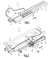
- Figure 1 is shown in perspective a guide mechanism of a seat for a motor vehicle, designated by general reference 2.
- the mechanism 2 is intended to connect a seat 4 shown schematically by a bracket to the structure 6 of a motor vehicle, such as a frame. It is particularly suitable for use in vehicles commonly called "minivan" which include three rows of seats arranged one behind the other in the direction of movement of the car. In this case, the mechanism 2 connects the seats of the middle row to the vehicle structure, to allow access to the seats of the rear row.
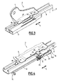
- the mechanism 2 is provided with a slide 8, which is fixed to the structure 6 of the vehicle, and a slide 10 to which the seat 4 is fixed. sliding in a rectilinear sliding direction C in the slide 8 between a rear position of the seat (FIGS. 1 and 2), a front position of the seat (FIGS. 3 and 4), and a position of access to the rear seats of the seat ( Figure 5).
- the front position is between the access position and the rear position.
- the guiding mechanism 2 comprises a locking device which selectively locks the slider 10 in the slider 8 when the slider 10 is between its front and rear positions. This device is not shown since it is known per se.
- tubular section 11 integral with the slide 8 extends along it.
- the mechanism 2 also comprises means for returning the slide 10 relative to the slide 8 in the form of an elastic cable 12 (see FIG. 2) of the "SANDOW®" type.
- This elastic cable 12 is adapted to urge the slider 10 by a pulling force towards the rear position of the seat 4 when the slider 10 is between the front and rear positions.
- the elastic cable 12 is provided with a first end 14, which is fixed permanently to the slide 8 via the profile 11, and a second end 16, which is connected to the slide 10.
- the mechanism 2 further comprises inhibition means 20, adapted to inhibit the action of the elastic cable 12 on the slider 10 when the latter is between the front position and the access position.
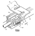
- the inhibition means 20 comprise a piece of 22, which is fixed integrally to the second end 16, a return hook 24, which is articulated to the guide piece 22 about an axis XX extending perpendicularly to the sliding direction C, and a slot 26 formed in a fitting 28 secured to the slider 10 via the seat 4.
- the guide piece 22 is a cylindrical sleeve 22A provided with flanges 22B which is slidably guided along the direction C in the profile 11.
- the return hook 24 is movable on the guide piece 22 between a return position shown in FIGS. , in which it engages in the slot 26, and a release position, in which it is shifted about the axis XX so as to disengage the slot 26.
- the return hook 24 is biased towards its return position by a first spring 27 hooked to the piece 22 (see Figure 7).
- the mechanism 2 further comprises means for automatically triggering the inhibition means 20, when the slider 10 has moved from the forward position to the access position and reached a release position located near the front position, but between this position and the access position.
- triggering means comprise an actuating finger 30 integral with the hook 24 (see FIG. 7), and a first actuating nose 32 integral with the tubular profile 11. This finger 30 and this nose 32 are arranged in such a way that the hook 24 is tilted into its release position when the slider 10 is moved beyond the front position to the access position.
- the mechanism 2 comprises holding means adapted to hold the guide piece 22 and the cable 12 in their configuration taken when the seat 4 passes the front position towards the access position and reaches a holding position between the front position and the release position.
- These holding means comprise a holding hook 34 which is articulated on the guide piece 22 about the axis XX, and which is adapted to engage in an opening 36 formed in the tubular section 11, when the seat 4 passes its forward position to the access position (see Figures 1 and 5) and reaches the holding position.
- This holding hook 34 is movable between an engagement position in the opening 36 and a disengaging position in which it extends outside this opening 36.
- the mechanism 2 further comprises means 38 adapted to stop the inhibition of the means 20 automatically when the slider 10 passes the front position to the rear position.
- These means 38 comprise a first ramp 40 which is disposed on the nose 32, which is directed towards the front of the vehicle, and which is adapted to bring the return hook 24 by an action on the actuating finger 30 in its position of release, so that the fitting 28 can cross the hook 24, then bring the hook 24 back to its return position, thus engaging the hook 24 in the slot 26.
- the ramp 40 and the actuating finger 30 are designed such that the return hook 24 is engaged when the seat 4 reaches the trigger position.
- the means 38 further comprise a second nose 42, integral with the holding hook 34, and a ramp 44 which is arranged on the fitting 28 and which is adapted to push the holding hook 34 out of the opening 36 when the seat 4 has reached its holding position when moving it to its rear position.
- the nose 42 and the ramp 44 are arranged in such a way that they only swing the hook 34 when the return hook is already engaged in the slot 26.
- the mechanism 2 according to the invention operates as follows.
- the seat 4 When a passenger wishes to use the seat 4, it actuates the not shown locking device, and can then slide the seat 4 between its rear and front positions. During this movement, the seat 4 is permanently resiliently biased towards its rear position by means of the elastic cable 12, the guide piece 22, the hook 24 and the slot 26.
- the seat 4 With the elastic cable 12, the seat 4 is biased towards the rear position, which increases the ergonomics of the displacement of the seat.
- the user When the user wishes to access seats that are located behind the seat 4, it actuates a rear seat access control that is not shown, which allows the seat back 4 to bow, and which simultaneously unlocks the not shown locking device.
- the slider 10 can move in the slide 8. Then the user pushes the seat 4 forward.
- the holding hook 34 engages from the holding position in the opening 36 and locking the guide piece 22 in its position corresponding to the front position.
- the finger 30 is applied against the nose 32, and tilts the hook 24 in its release position.
- the ramp 44 is applied against the nose 42, and tilts the holding hook 34 in its disengaged position. From this position which is the holding position, the cable 12 again urges the seat 4 towards the rear position.
- the distances between the forward position, the holding position and the release position are very small and are just large enough to allow safe maintenance of the part 22 before release thereof from the slider 10.
- the mechanism 2 according to the invention leads to good ergonomics of use, since on the one hand, between the rear and front positions, the seat 4 is recalled in a definite manner towards its rear position, and on the other hand on the other hand, when the seat 4 is moved between its front and rear seats, it can be moved freely and with little effort.
- the securing of the slider 10 to the elastic cable 12, and the separation is performed in an automatic manner and does not require additional action of the user.
- the mechanism uses only mechanical components and does not consume electrical energy during use.
- the invention can also be applied to the front seats of the vehicle of the three-door type.
Landscapes
- Engineering & Computer Science (AREA)
- Aviation & Aerospace Engineering (AREA)
- Transportation (AREA)
- Mechanical Engineering (AREA)
- Seats For Vehicles (AREA)
Priority Applications (1)
| Application Number | Priority Date | Filing Date | Title |
|---|---|---|---|
| EP06300349A EP1844974A1 (de) | 2006-04-11 | 2006-04-11 | Führungsmechanismus eines Sitzes und entsprechendes Kraftfahrzeug |
Applications Claiming Priority (1)
| Application Number | Priority Date | Filing Date | Title |
|---|---|---|---|
| EP06300349A EP1844974A1 (de) | 2006-04-11 | 2006-04-11 | Führungsmechanismus eines Sitzes und entsprechendes Kraftfahrzeug |
Publications (1)
| Publication Number | Publication Date |
|---|---|
| EP1844974A1 true EP1844974A1 (de) | 2007-10-17 |
Family
ID=36950348
Family Applications (1)
| Application Number | Title | Priority Date | Filing Date |
|---|---|---|---|
| EP06300349A Withdrawn EP1844974A1 (de) | 2006-04-11 | 2006-04-11 | Führungsmechanismus eines Sitzes und entsprechendes Kraftfahrzeug |
Country Status (1)
| Country | Link |
|---|---|
| EP (1) | EP1844974A1 (de) |
Cited By (1)
| Publication number | Priority date | Publication date | Assignee | Title |
|---|---|---|---|---|
| CN106240407B (zh) * | 2016-08-25 | 2019-01-15 | 成都市天龙交通设备有限公司 | 移动底座机构及装配方法 |
Citations (3)
| Publication number | Priority date | Publication date | Assignee | Title |
|---|---|---|---|---|
| FR2746063A1 (fr) * | 1996-03-12 | 1997-09-19 | Peugeot | Dispositif permettant de faciliter le deplacement d'un siege de vehicule automobile vers l'avant de celui-ci |
| EP1500551A2 (de) * | 2003-07-23 | 2005-01-26 | Aisin Seiki Kabushiki Kaisha | Sitzvorrichtung |
| FR2876636A1 (fr) * | 2004-10-18 | 2006-04-21 | Peugeot Citroen Automobiles Sa | Mecanisme de guidage d'un siege et vehicule automobile correspondant |
-
2006
- 2006-04-11 EP EP06300349A patent/EP1844974A1/de not_active Withdrawn
Patent Citations (3)
| Publication number | Priority date | Publication date | Assignee | Title |
|---|---|---|---|---|
| FR2746063A1 (fr) * | 1996-03-12 | 1997-09-19 | Peugeot | Dispositif permettant de faciliter le deplacement d'un siege de vehicule automobile vers l'avant de celui-ci |
| EP1500551A2 (de) * | 2003-07-23 | 2005-01-26 | Aisin Seiki Kabushiki Kaisha | Sitzvorrichtung |
| FR2876636A1 (fr) * | 2004-10-18 | 2006-04-21 | Peugeot Citroen Automobiles Sa | Mecanisme de guidage d'un siege et vehicule automobile correspondant |
Cited By (1)
| Publication number | Priority date | Publication date | Assignee | Title |
|---|---|---|---|---|
| CN106240407B (zh) * | 2016-08-25 | 2019-01-15 | 成都市天龙交通设备有限公司 | 移动底座机构及装配方法 |
Similar Documents
| Publication | Publication Date | Title |
|---|---|---|
| EP2616616B1 (de) | Kraftfahrzeugsgriff mit einem trägheitskörper und einer sicherung | |
| EP3456579A1 (de) | Gleitschiene für fahrzeugsitz, und fahrzeugsitz, der eine solche gleitschiene umfasst | |
| EP2295287B1 (de) | Befestigungsbasis für einen Autokindersitz | |
| EP1642776B1 (de) | Montagesystem einer Gepäckraumabdeckung mit einer Schiene | |
| WO2018073518A1 (fr) | Volant pour véhicule automobile autonome | |
| EP2072327B1 (de) | Freigabeeinrichtung des Gepäckladeraums eines Kraftfahrzeugs | |
| EP1844974A1 (de) | Führungsmechanismus eines Sitzes und entsprechendes Kraftfahrzeug | |
| FR2876636A1 (fr) | Mecanisme de guidage d'un siege et vehicule automobile correspondant | |
| EP3724429B1 (de) | Griffhalterung für ein kraftfahrzeug | |
| EP3350016B1 (de) | Verriegelungsvorrichtung für zwei positionen einer hintersitz-rückenlehne eines kraftfahrzeugs | |
| EP3619439B1 (de) | Vorrichtung zum einstellen eines kraftfahrzeugsitzbetätigungskabels | |
| FR3104501A1 (fr) | Ensemble de siège de véhicule | |
| EP2104622B1 (de) | Diebstahlsicherungsvorrichtung für ein fahrzeug mit einem eine elastische nase aufweisenden schieber | |
| EP3253616B1 (de) | Banksitz mit verstellbaren sitzlehnen mit je einem separaten eingebauten system für einklemmschutz | |
| FR3004393A1 (fr) | Mecanisme de liaison pivotante pour siege de vehicule et siege comprenant un tel mecanisme | |
| FR3012383A1 (fr) | Siege escamotable pour vehicule | |
| EP4043290B1 (de) | Haltevorrichtung für ein tragbares elektronisches gerät in einem kraftfahrzeug | |
| EP2196355A1 (de) | Einrastvorrichtung zum Fixieren eines Teils der Rückenlehne eines Autositzes auf einem Strukturteil des Fahrzeugs, und entsprechendes Fahrzeug | |
| EP3162614B1 (de) | Sitz für fahrzeug, der einen begrenzungsmechanismus für das verschieben hat | |
| FR2888794A1 (fr) | Systeme de reglage et de blocage en translation d'une tige, notamment pour appui-tete de vehicule automobile | |
| EP2359990B1 (de) | Sicherheitsmesser | |
| EP2503082B1 (de) | Motorised lock for automobile | |
| EP3921230B1 (de) | Auswurfsystem für einen notausstieg eines fahrzeugs | |
| FR3106357A1 (fr) | Dispositif d’accès de secours d’ouvrant de véhicule | |
| FR3043712B1 (fr) | Systeme de commande d'ouverture d'ouvrant de vehicule automobile |
Legal Events
| Date | Code | Title | Description |
|---|---|---|---|
| PUAI | Public reference made under article 153(3) epc to a published international application that has entered the european phase |
Free format text: ORIGINAL CODE: 0009012 |
|
| AK | Designated contracting states |
Kind code of ref document: A1 Designated state(s): AT BE BG CH CY CZ DE DK EE ES FI FR GB GR HU IE IS IT LI LT LU LV MC NL PL PT RO SE SI SK TR |
|
| AX | Request for extension of the european patent |
Extension state: AL BA HR MK YU |
|
| 17P | Request for examination filed |
Effective date: 20080417 |
|
| 17Q | First examination report despatched |
Effective date: 20080519 |
|
| AKX | Designation fees paid |
Designated state(s): AT BE BG CH CY CZ DE DK EE ES FI FR GB GR HU IE IS IT LI LT LU LV MC NL PL PT RO SE SI SK TR |
|
| GRAP | Despatch of communication of intention to grant a patent |
Free format text: ORIGINAL CODE: EPIDOSNIGR1 |
|
| GRAS | Grant fee paid |
Free format text: ORIGINAL CODE: EPIDOSNIGR3 |
|
| STAA | Information on the status of an ep patent application or granted ep patent |
Free format text: STATUS: THE APPLICATION IS DEEMED TO BE WITHDRAWN |
|
| 18D | Application deemed to be withdrawn |
Effective date: 20110712 |