EP1845019A1 - Vorrichtung zur Herstellung von hülsenförmigen Folienhüllen aus einem durchgehenden flachen Streifen von hülsenförmigem Folienmaterial - Google Patents
Vorrichtung zur Herstellung von hülsenförmigen Folienhüllen aus einem durchgehenden flachen Streifen von hülsenförmigem Folienmaterial Download PDFInfo
- Publication number
- EP1845019A1 EP1845019A1 EP20070007265 EP07007265A EP1845019A1 EP 1845019 A1 EP1845019 A1 EP 1845019A1 EP 20070007265 EP20070007265 EP 20070007265 EP 07007265 A EP07007265 A EP 07007265A EP 1845019 A1 EP1845019 A1 EP 1845019A1
- Authority
- EP
- European Patent Office
- Prior art keywords
- sleeve
- cutting
- strip
- foil material
- foil
- Prior art date
- Legal status (The legal status is an assumption and is not a legal conclusion. Google has not performed a legal analysis and makes no representation as to the accuracy of the status listed.)
- Granted
Links
- 239000011888 foil Substances 0.000 title claims abstract description 140
- 239000000463 material Substances 0.000 title claims abstract description 104
- 238000005520 cutting process Methods 0.000 claims abstract description 124
- 238000007599 discharging Methods 0.000 claims abstract description 5
- 238000001514 detection method Methods 0.000 claims description 3
- 238000010276 construction Methods 0.000 description 2
- 238000007789 sealing Methods 0.000 description 2
- 238000009825 accumulation Methods 0.000 description 1
- 230000005540 biological transmission Effects 0.000 description 1
- 230000008878 coupling Effects 0.000 description 1
- 238000010168 coupling process Methods 0.000 description 1
- 238000005859 coupling reaction Methods 0.000 description 1
- 238000010438 heat treatment Methods 0.000 description 1
Images



Classifications
-
- B—PERFORMING OPERATIONS; TRANSPORTING
- B65—CONVEYING; PACKING; STORING; HANDLING THIN OR FILAMENTARY MATERIAL
- B65B—MACHINES, APPARATUS OR DEVICES FOR, OR METHODS OF, PACKAGING ARTICLES OR MATERIALS; UNPACKING
- B65B61/00—Auxiliary devices, not otherwise provided for, for operating on sheets, blanks, webs, binding material, containers or packages
- B65B61/04—Auxiliary devices, not otherwise provided for, for operating on sheets, blanks, webs, binding material, containers or packages for severing webs, or for separating joined packages
- B65B61/06—Auxiliary devices, not otherwise provided for, for operating on sheets, blanks, webs, binding material, containers or packages for severing webs, or for separating joined packages by cutting
- B65B61/08—Auxiliary devices, not otherwise provided for, for operating on sheets, blanks, webs, binding material, containers or packages for severing webs, or for separating joined packages by cutting using rotary cutters
-
- B—PERFORMING OPERATIONS; TRANSPORTING
- B26—HAND CUTTING TOOLS; CUTTING; SEVERING
- B26D—CUTTING; DETAILS COMMON TO MACHINES FOR PERFORATING, PUNCHING, CUTTING-OUT, STAMPING-OUT OR SEVERING
- B26D3/00—Cutting work characterised by the nature of the cut made; Apparatus therefor
- B26D3/12—Slitting marginal portions of the work, i.e. forming cuts, without removal of material, at an angle, e.g. a right angle, to the edge of the work
-
- B—PERFORMING OPERATIONS; TRANSPORTING
- B65—CONVEYING; PACKING; STORING; HANDLING THIN OR FILAMENTARY MATERIAL
- B65B—MACHINES, APPARATUS OR DEVICES FOR, OR METHODS OF, PACKAGING ARTICLES OR MATERIALS; UNPACKING
- B65B9/00—Enclosing successive articles, or quantities of material, e.g. liquids or semiliquids, in flat, folded, or tubular webs of flexible sheet material; Subdividing filled flexible tubes to form packages
- B65B9/10—Enclosing successive articles, or quantities of material, in preformed tubular webs, or in webs formed into tubes around filling nozzles, e.g. extruded tubular webs
- B65B9/13—Enclosing successive articles, or quantities of material, in preformed tubular webs, or in webs formed into tubes around filling nozzles, e.g. extruded tubular webs the preformed tubular webs being supplied in a flattened state
- B65B9/14—Devices for distending tubes supplied in the flattened state
-
- B—PERFORMING OPERATIONS; TRANSPORTING
- B65—CONVEYING; PACKING; STORING; HANDLING THIN OR FILAMENTARY MATERIAL
- B65C—LABELLING OR TAGGING MACHINES, APPARATUS, OR PROCESSES
- B65C3/00—Labelling other than flat surfaces
- B65C3/06—Affixing labels to short rigid containers
- B65C3/065—Affixing labels to short rigid containers by placing tubular labels around the container
-
- B—PERFORMING OPERATIONS; TRANSPORTING
- B65—CONVEYING; PACKING; STORING; HANDLING THIN OR FILAMENTARY MATERIAL
- B65C—LABELLING OR TAGGING MACHINES, APPARATUS, OR PROCESSES
- B65C9/00—Details of labelling machines or apparatus
- B65C9/0065—Cutting tubular labels from a web
-
- B—PERFORMING OPERATIONS; TRANSPORTING
- B26—HAND CUTTING TOOLS; CUTTING; SEVERING
- B26D—CUTTING; DETAILS COMMON TO MACHINES FOR PERFORATING, PUNCHING, CUTTING-OUT, STAMPING-OUT OR SEVERING
- B26D1/00—Cutting through work characterised by the nature or movement of the cutting member or particular materials not otherwise provided for; Apparatus or machines therefor; Cutting members therefor
- B26D1/01—Cutting through work characterised by the nature or movement of the cutting member or particular materials not otherwise provided for; Apparatus or machines therefor; Cutting members therefor involving a cutting member which does not travel with the work
- B26D1/12—Cutting through work characterised by the nature or movement of the cutting member or particular materials not otherwise provided for; Apparatus or machines therefor; Cutting members therefor involving a cutting member which does not travel with the work having a cutting member moving about an axis
- B26D1/25—Cutting through work characterised by the nature or movement of the cutting member or particular materials not otherwise provided for; Apparatus or machines therefor; Cutting members therefor involving a cutting member which does not travel with the work having a cutting member moving about an axis with a non-circular cutting member
- B26D1/34—Cutting through work characterised by the nature or movement of the cutting member or particular materials not otherwise provided for; Apparatus or machines therefor; Cutting members therefor involving a cutting member which does not travel with the work having a cutting member moving about an axis with a non-circular cutting member moving about an axis parallel to the line of cut
- B26D1/38—Cutting through work characterised by the nature or movement of the cutting member or particular materials not otherwise provided for; Apparatus or machines therefor; Cutting members therefor involving a cutting member which does not travel with the work having a cutting member moving about an axis with a non-circular cutting member moving about an axis parallel to the line of cut and coacting with a fixed blade or other fixed member
- B26D1/385—Cutting through work characterised by the nature or movement of the cutting member or particular materials not otherwise provided for; Apparatus or machines therefor; Cutting members therefor involving a cutting member which does not travel with the work having a cutting member moving about an axis with a non-circular cutting member moving about an axis parallel to the line of cut and coacting with a fixed blade or other fixed member for thin material, e.g. for sheets, strips or the like
-
- B—PERFORMING OPERATIONS; TRANSPORTING
- B26—HAND CUTTING TOOLS; CUTTING; SEVERING
- B26D—CUTTING; DETAILS COMMON TO MACHINES FOR PERFORATING, PUNCHING, CUTTING-OUT, STAMPING-OUT OR SEVERING
- B26D11/00—Combinations of several similar cutting apparatus
-
- B—PERFORMING OPERATIONS; TRANSPORTING
- B26—HAND CUTTING TOOLS; CUTTING; SEVERING
- B26F—PERFORATING; PUNCHING; CUTTING-OUT; STAMPING-OUT; SEVERING BY MEANS OTHER THAN CUTTING
- B26F1/00—Perforating; Punching; Cutting-out; Stamping-out; Apparatus therefor
- B26F1/18—Perforating by slitting, i.e. forming cuts closed at their ends without removal of material
- B26F1/20—Perforating by slitting, i.e. forming cuts closed at their ends without removal of material with tools carried by a rotating drum or similar support
-
- Y—GENERAL TAGGING OF NEW TECHNOLOGICAL DEVELOPMENTS; GENERAL TAGGING OF CROSS-SECTIONAL TECHNOLOGIES SPANNING OVER SEVERAL SECTIONS OF THE IPC; TECHNICAL SUBJECTS COVERED BY FORMER USPC CROSS-REFERENCE ART COLLECTIONS [XRACs] AND DIGESTS
- Y10—TECHNICAL SUBJECTS COVERED BY FORMER USPC
- Y10T—TECHNICAL SUBJECTS COVERED BY FORMER US CLASSIFICATION
- Y10T83/00—Cutting
- Y10T83/465—Cutting motion of tool has component in direction of moving work
- Y10T83/4653—With means to initiate intermittent tool action
- Y10T83/4656—Tool moved in response to work-sensing means
-
- Y—GENERAL TAGGING OF NEW TECHNOLOGICAL DEVELOPMENTS; GENERAL TAGGING OF CROSS-SECTIONAL TECHNOLOGIES SPANNING OVER SEVERAL SECTIONS OF THE IPC; TECHNICAL SUBJECTS COVERED BY FORMER USPC CROSS-REFERENCE ART COLLECTIONS [XRACs] AND DIGESTS
- Y10—TECHNICAL SUBJECTS COVERED BY FORMER USPC
- Y10T—TECHNICAL SUBJECTS COVERED BY FORMER US CLASSIFICATION
- Y10T83/00—Cutting
- Y10T83/465—Cutting motion of tool has component in direction of moving work
- Y10T83/4705—Plural separately mounted flying cutters
-
- Y—GENERAL TAGGING OF NEW TECHNOLOGICAL DEVELOPMENTS; GENERAL TAGGING OF CROSS-SECTIONAL TECHNOLOGIES SPANNING OVER SEVERAL SECTIONS OF THE IPC; TECHNICAL SUBJECTS COVERED BY FORMER USPC CROSS-REFERENCE ART COLLECTIONS [XRACs] AND DIGESTS
- Y10—TECHNICAL SUBJECTS COVERED BY FORMER USPC
- Y10T—TECHNICAL SUBJECTS COVERED BY FORMER US CLASSIFICATION
- Y10T83/00—Cutting
- Y10T83/525—Operation controlled by detector means responsive to work
- Y10T83/541—Actuation of tool controlled in response to work-sensing means
- Y10T83/543—Sensing means responsive to work indicium or irregularity
-
- Y—GENERAL TAGGING OF NEW TECHNOLOGICAL DEVELOPMENTS; GENERAL TAGGING OF CROSS-SECTIONAL TECHNOLOGIES SPANNING OVER SEVERAL SECTIONS OF THE IPC; TECHNICAL SUBJECTS COVERED BY FORMER USPC CROSS-REFERENCE ART COLLECTIONS [XRACs] AND DIGESTS
- Y10—TECHNICAL SUBJECTS COVERED BY FORMER USPC
- Y10T—TECHNICAL SUBJECTS COVERED BY FORMER US CLASSIFICATION
- Y10T83/00—Cutting
- Y10T83/727—With means to guide moving work
Definitions
- the invention relates to a device for forming sleeve-like foil envelopes from a continuous flat strip of a sleeve-like foil material, comprising supply means for supplying the continuous flat strip of sleeve-like foil material, cutting means for making a cut in this strip of sleeve-like foil material over the full width thereof so as to obtain the individual sleeve-like foil envelopes, as well as discharge means for discharging the individual sleeve-like foil envelopes from the device.
- Such a device is for example disclosed in European patent publication no. 0 805 110 .
- individual sleeve-like foil envelopes are realised in one cutting motion, which individual, flat, sleeve-like foil envelopes must subsequently be opened and be placed round an object, such as a bottle or other container, with a slight oversize.
- the foil material that is used is made of a so-called “shrink material", which will shrink under the influence of heat being supplied thereto and conform tightly to the shape of the bottle or other container round which the foil envelope has been placed.
- the foil envelope has already been made in the form of a continuous strip wound on a roll, which needs to be cut to the correct length by means of a device as mentioned in the introduction.
- the cutting means are driven in dependence on the length, in such a manner that they cut the strip of sleeve-like foil material to the correct length, after which the individual sleeve-like foil envelope thus formed is discharged from the device and opened to be subsequently placed round the container in a manner which is known per se.
- a drawback of the device that is currently known is that it is only suitable for use with thick or hard foil materials in order to thus realise a high processing rate.
- the processing speed must be reduced in order to prevent the device from undesirably getting jammed.
- the object of the invention is to obviate these drawbacks and to provide a device as mentioned in the introduction in which large numbers of foil envelopes of varying length and varying types of material can be formed with a high processing rate.
- the device is to that end characterised in that the cutting means comprise at least two cutting elements that are movable relative to the flat strip of sleeve-like foil material, each cutting element comprising at least one cutting blade extending parallel to at least part of the width of the strip, in such a manner that the individual cutting blades of the cutting elements form several partial cuts contiguous to each other in the strip of sleeve-like foil material over the entire width thereof in successive cutting operations.
- the processing speed can be increased significantly by forming the cuts in the continuous strip of sleeve-like material in phases, whilst preventing any jamming or clogging of the device. Furthermore, this construction, in which several partial cuts are formed in succession in the foil material, makes it possible to user thinner foil materials.
- the cutting blades of the various cutting elements are arranged in at least partially overlapping relationship adjacent to each other, as a result of which a tight cut is formed over the entire width of the strip, thus making it possible to realise individual foil envelopes.
- each cutting element comprises one cutting blade, whilst in another embodiment at least one cutting element comprises at least two cutting blades.
- the cutting elements are arranged some distance apart along the continuous flat strip of sleeve-like foil material, seen in the direction of transport of the continuous flat strip of sleeve-like foil material.
- the high processing speed can be realised in particular in that in a functional embodiment of the device according to the invention the cutting elements are each rotatable about an axis parallel to the width of the strip off sleeve-like foil material. This makes it possible to realise a simple and robust construction, which moreover makes it possible to drive the device in a continuous (and reliable) manner at a high processing speed.
- the cutting elements rotate at identical rotational speeds, whilst in another embodiment the rotational speed of each cutting element can be varied during one rotation, so that the processing speed can be adapted to, for example, the length of the foil envelopes to be realised, the type of foil material (thickness, etc), etc.
- the rotational speed of each cutting element is substantially identical to the speed of transport of the strip of sleeve-like foil material through the device at the moment when the partial cut is formed.
- the conveying means comprise a guide element over which the strip of sleeve-like foil material can be led during operation.
- the guide element may be configured as a flat member in that case.
- the continuous strip of foil material is prevented from undesirably getting jammed in the device in that the guide element extends beyond the cutting means, seen in the direction of transport of the strip of sleeve-like foil material.
- the device in order to place an originally flat foil envelope over a three-dimensional product, such as a container (a can, a jar, a bottle) in an effective manner, the device is provided with a spreading element for opening each individual flat sleeve-like foil envelope at a location downstream of the cutting means, seen in the direction of transport of the strip of sleeve like the like foil material.
- said spreading element is enlarged at least in the plane perpendicular to the plane of the flat strip of foil material. Said placement of the envelope over the product can be further improved if in another embodiment the spreading element is enlarged in the plane of the flat strip of foil material.
- the spreading element may be mounted to the guide element.
- discharge means may be disposed near the spreading element for discharging the individual sleeve-like foil envelopes that have been formed from the device.
- the device is provided with at least one sensor, which is arranged for detecting markings provided some distance apart on the continuous strip of sleeve-like foil material and delivering a measuring signal on the basis of said detection, on the basis of which measuring signal the cutting means form partial cuts in the strip of sleeve-like foil material.
- at least one sensor which is arranged for detecting markings provided some distance apart on the continuous strip of sleeve-like foil material and delivering a measuring signal on the basis of said detection, on the basis of which measuring signal the cutting means form partial cuts in the strip of sleeve-like foil material.
- control means may be provided in that case, which control means control the cutting means on the basis of the measuring signal delivered by the sensor, a specified length of the sleeve-like foil envelopes to be formed and the conveying speed of the strip of sleeve-like foil material.
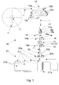
- numeral 10 indicates a device according to the invention.
- the device 10 comprises supply means or moving means 12 made up of two drivable rollers, between which a continuous strip of foil material 1 can be carried.
- the continuous strip of foil material 1 is wound on a supply reel 11 and is introduced into the device via a tensioning mechanism 13.
- the tensioning mechanism 13 has an arm 13a, which is pivotally connected to the fixed structure 100.
- the pivot arm 13a comprises several rollers 13b, over which the continuous strip of sleeve-like foil material 1 is passed.
- the strip of sleeve-like foil material 1 is also passed over additional, fixedly disposed rollers 13c. In this way it is possible to realise a certain supply of but above all also a certain tension of the continuous strip of sleeve-like foil material being unwound from the reel 11.
- the continuous strip of sleeve-like foil material is built up of two strip sides 1 a, 1 b, which are connected along at least one longitudinal side, for example by means of a sealing seam.
- the supply means 12 carry the continuous strip of sleeve-like foil material 1 past cutting means for cutting the foil material through at predetermined intervals so as to obtain individual sleeve-like foil envelopes.
- the cutting means are made up of two clamping sections 14-15, which each comprise cutting elements 14-15 that are movable with respect to the flat strip of sleeve-like foil material 1, each cutting element 14-15 being provided with at least one cutting blade 14';15'-15", which extends at least parallel to at least part of the width of the strip of foil material.
- the cutting elements 14-15 are arranged some distance apart along the continuous strip of sleeve-like foil material 1, seen in the direction of transport of the continuous strip.
- the cutting elements 14-15 are each rotatable about their axis parallel to the width of the strip of sleeve-like foil material 1, as is clearly shown in Figures 2 and 3.
- the two cutting elements 14-15 are driven in such a manner that they successively form partial cuts in the continuous strip of foil material in successive operating steps, which partial cuts will eventually be aligned and be contiguous to each other, thus forming a complete cut for realising or forming an individual sleeve-like foil envelope.
- the forming of contiguous partial cuts by two separate cutting elements 14-15 requires a correct adjustment or control of the cutting elements, taking into account also the conveying speed of the continuous strip of sleeve-like foil material 1 through the device.
- the device is provided with a sensor 16, which is arranged for detecting markings (not shown) present in or on the continuous strip of foil material 1.
- Said markings are in particular arranged at regular intervals and preferably consist of a strip of foil material which has been made reflective or, on the contrary, a strip of a transparent foil material.
- the sensor 16 may be configured as a light sensor which detects the presence of a marking on the strip of foil material 1 on the basis of reflected or transmitted light and which is capable of determining the conveying speed, for example, of the strip of foil material 1 through the device on the basis of successive detections. Given a desired length of the individual sleeve-like a foil envelopes, the two cutting elements 14-15 are rotatably driven accordingly.
- Rotation of the cutting element 14 or 15 places the cutting blade 14' or 15'-15" into abutment against a fixedly disposed anvil 14a-15a, as a result of which a partial cut is formed in the continuous strip of foil material 1 that is present therebetween.
- the first cutting element 14 and the cutting blade 14' form a first partial cut in the continuous strip of foil material 1.
- the strip 1 is moved further by the supply means 12 and the control unit 25 will control the second cutting element 15 in such a manner that the cutting blades 50'-15" will be contiguous to the partial cut formed by the cutting blade 14' of the first cutting element 14.
- the rotational speeds of the cutting elements 14-15 may in principle be the same and be geared to the conveying speed of the strip of foil material and the desired length of the final sleeve-like foil envelopes, the device according to the invention may be operated at a higher speed by making the rotational speed of each cutting element variable during one rotation.
- rotational speeds may be used for the cutting elements 14-15, whilst the rotational speed of each cutting element may be substantially equal to the conveying speed of the strip of sleeve-like foil material 1 through the device at the moment of forming the partial cut in order to form good quality and in particular correctly contiguous (read: coinciding) cuts. This is determined in particular by the properties of the foil material that is used, however.
- the cutting elements 14-15 are rotatably driven by suitable driving means 140-150, which are controlled by the control unit 25.
- Each cutting element 14-15 is bearing-mounted in the device by means of bearings 142-152 and drivably connected to the driving means 140-150 by means of transmission couplings 141-151.
- a guide element 17 is provided in the device, over which guide element 17 the strip of sleeve-like foil material 1 can be passed.
- the guide element 17 comprises a support element 17a in the shape of a rotatable roller, which is supported by freely rotatable roll pins 18a-18b, which likewise form part of the device.
- the guide element 17 is freely supported in the device by the support rollers 18a-18b.
- the guide element is preferably configured as a flat body having a width substantially equal to the width of the strip of sleeve-like foil material 1. More specifically, the guide element 17 is so constructed that material has been removed from the guide element 17 at the location of the cutting elements 14 and 15 so as to make it possible to form a partial cuts in the continuous strip of sleeve-like foil material 1.
- the locations where material has been removed from the guide element 17 are indicated at 17' in figures 2 and 3 (at the location of the cutting blade 14' of the first cutting element 14) and at 17" (at the location of the two cutting blades 15'-15" of the second cutting element 15).
- the free end 17b of the guide element 17a serves to accommodate a spreading element 19, which functions to open the obtained flat, sleeve-like foil envelopes 1' in order to place the opened, sleeve-like foil envelope around a container (not shown).
- the spreading element 19 is enlarged at least in the plane perpendicular to the plane of the flat, continuous strip of foil material 1. This is shown in figures 1 and 2.
- the spreading element may also be enlarged in the plane of the flat strip of foil material, as is shown in Figure 3.
- FIGS. 1 and 3 show conveying means 21 provided with a carrier 21 a with several containers (bottles, jars or cans) present thereon, which containers are carried to the device 10.
- a carrier 21 a with several containers (bottles, jars or cans) present thereon, which containers are carried to the device 10.
- Each individual, flat, sleeve-like foil envelope is opened by the spreading element 19, after which the sleeve-like foil envelope 1' thus opened can be easily placed round the container 2.
- the use of so-called vacuum cups 21 b as described in European patent publication No. 1 151 847 in the name of the present applicant, may contribute towards keeping the sleeve-like foil envelope 1 ' open.
- the container 2 with the opened sleeve-like foil envelope provided thereon may now be subjected to a heat treatment, so that the sleeve-like foil envelop will shrink and conform tightly to the shape of the container 2.
- discharge means 20a-20b may be provided, which are mounted in the device at the spreading element 19.
- Said discharge means may comprise one or more drivable rollers 20a, which are supported on the stationary rollers 20b and which discharge the sleeve-like foil material 1' present therebetween from the device 10 at an accelerated rate, with the individual, opened foil envelope 1' slipping over a container 2, as it were.
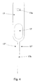
- FIGS 5a-5c show three further schematic embodiments of the device according to the invention, more in particular of the cutting means 14-15.
- Subfigure 5a shows the embodiment as discussed with reference to figures 2 and 3, in which the first cutting element 14 comprises one cutting blade 14', which is oriented approximately centrally relative to the continuous strip of sleeve-like foil material 1.
- the cutting blade 14' of the first cutting element 14 forms a first partial cut in the first operating step, after which the second cutting element 15 forms further partial cuts contiguous thereto in the foil material 1 on either side of said centrally positioned partial cut by means of two cutting blades 15'-15", so that the continuous strip of sleeve-like foil material 1 is cut through completely so as to obtain an individual sleeve-like foil envelope.
- Subfigure 5b schematically shows another embodiment, in which the first cutting element 14 comprises two cutting blades 14'-14", similar to the second cutting element 15 in subfigure 5a.
- the second cutting element 15 comprises a single cutting blade 15', which is centrally oriented relative to the strip of foil material 1.
- two partial cuts 14'-14" are formed in the first operation, which in any case cut through the longitudinal edges of the strip of foil material 1. The cutting of the material is completed by the forming of the partial cut by means of the cutting blade 15' of the second cutting element 15.
- each cutting element 14-15 comprises one single cutting blade 14'-15', which is disposed to the left and to the right, respectively, (or to the right and to the left, respectively) of the continuous strip of sleeve-like foil material 1.
- the cutting blades 14'-14"-15'-15" are so arranged relative to each other and to the continuous strip of foil material 1 in the device that the partial cuts thus formed partially overlap so as to realise a complete cut through the foil material.
Landscapes
- Engineering & Computer Science (AREA)
- Mechanical Engineering (AREA)
- Life Sciences & Earth Sciences (AREA)
- Forests & Forestry (AREA)
- Making Paper Articles (AREA)
- Sealing Of Jars (AREA)
Applications Claiming Priority (1)
| Application Number | Priority Date | Filing Date | Title |
|---|---|---|---|
| NL1031597A NL1031597C2 (nl) | 2006-04-13 | 2006-04-13 | Inrichting voor het uit een strook hoesvormig foliemateriaal vervaardigen van hoesvormige folie-omhullingen. |
Publications (2)
| Publication Number | Publication Date |
|---|---|
| EP1845019A1 true EP1845019A1 (de) | 2007-10-17 |
| EP1845019B1 EP1845019B1 (de) | 2012-09-12 |
Family
ID=37533120
Family Applications (1)
| Application Number | Title | Priority Date | Filing Date |
|---|---|---|---|
| EP20070007265 Not-in-force EP1845019B1 (de) | 2006-04-13 | 2007-04-06 | Vorrichtung zur Herstellung von hülsenförmigen Folienhüllen aus einem durchgehenden flachen Streifen von hülsenförmigem Folienmaterial |
Country Status (5)
| Country | Link |
|---|---|
| US (1) | US7987755B2 (de) |
| EP (1) | EP1845019B1 (de) |
| JP (1) | JP4982714B2 (de) |
| ES (1) | ES2394975T3 (de) |
| NL (1) | NL1031597C2 (de) |
Cited By (4)
| Publication number | Priority date | Publication date | Assignee | Title |
|---|---|---|---|---|
| WO2013080818A1 (en) * | 2011-11-14 | 2013-06-06 | Fuji Seal International, Inc. | Film-fitting device |
| EP2876053A1 (de) * | 2013-11-20 | 2015-05-27 | Krones AG | Umlenkvorrichtung für einen Folienschlauch und Steuerungsvorrichtung für eine Umlenkvorrichtung |
| WO2016120901A1 (en) * | 2015-01-30 | 2016-08-04 | Clever Srl - Unipersonale | Precut device for a machine for the application of shrinking sleeve- labels and machine comprising the same |
| EP3007869B1 (de) * | 2013-06-13 | 2022-03-30 | Hengstler GmbH | Abschneider für streifenförmige materialien aller art, sowie damit geschnittene materialbahn |
Families Citing this family (7)
| Publication number | Priority date | Publication date | Assignee | Title |
|---|---|---|---|---|
| NL1033245C2 (nl) * | 2007-01-17 | 2008-07-18 | Fuji Seal Europe Bv | Inrichting voor het uit een strook hoesvormig foliemateriaal vervaardigen van hoesvormige folie-omhullingen. |
| US20090116643A1 (en) | 2007-10-31 | 2009-05-07 | Yasuo Hatano | Encryption apparatus, decryption apparatus, and cryptography system |
| IT1393147B1 (it) * | 2009-03-09 | 2012-04-11 | Sacmi Labelling S P A Ora Sacmi Verona S P A | Apparato e metodo di alimentazione |
| CN102343990B (zh) * | 2011-08-26 | 2014-08-13 | 上海宏曲电子科技有限公司 | 管状材料包装的下封切装置 |
| NL2007730C2 (en) * | 2011-11-07 | 2013-07-18 | Fuji Seal Europe Bv | Method and system for forming sleeved containers. |
| US20140116625A1 (en) * | 2012-10-26 | 2014-05-01 | Xu Yuan Packaging Technology Co., Ltd. | Pneumatic type heat shrink film applicator |
| CN118004495B (zh) * | 2024-04-08 | 2024-06-04 | 四川同人泰药业股份有限公司 | 一种用于食品药品包装的可定量出料的铝塑包装装置 |
Citations (7)
| Publication number | Priority date | Publication date | Assignee | Title |
|---|---|---|---|---|
| EP0338260A2 (de) * | 1988-04-18 | 1989-10-25 | Stobb Inc. | Papierbahnschneidevorrichtung |
| EP0368663A1 (de) * | 1988-11-10 | 1990-05-16 | Austin-Gordon Design, Inc | Vorrichtung zum Aufbringen von Schrumpffolienhülsen |
| EP0449006A2 (de) * | 1990-03-14 | 1991-10-02 | Littleton Industrial Consultants, Inc. | Vorrichtung und Verfahren zum Abtrennen von Papierbahnen |
| GB2256828A (en) * | 1991-06-22 | 1992-12-23 | Roland Man Druckmasch | Cross-cutting and/or cross perforating webs |
| FR2738797A1 (fr) * | 1995-09-15 | 1997-03-21 | Sabatier Eric | Machine a chemiser des objets en forme au moyen de troncons de gaine thermo-retractable |
| US5740709A (en) * | 1994-03-30 | 1998-04-21 | Goss Graphic Systems, Inc. | Two stage continuous web cutting system and method |
| US5791220A (en) * | 1996-08-28 | 1998-08-11 | Benison & Co., Ltd. | Cutting device of packing apparatus |
Family Cites Families (34)
| Publication number | Priority date | Publication date | Assignee | Title |
|---|---|---|---|---|
| DE1460141A1 (de) * | 1964-08-01 | 1968-12-19 | Schubert & Salzer Maschinen | Verfahren und Vorrichtung zum selbsttaetigen Zuschneiden textiler Stoffe |
| US3347119A (en) * | 1965-03-10 | 1967-10-17 | Harris Intertype Corp | Cutting method and apparatus |
| US3448646A (en) * | 1966-01-28 | 1969-06-10 | Deritend Eng Co | Treatment of continuous webs |
| US3542618A (en) * | 1967-09-25 | 1970-11-24 | Donald H Devaughn | Method of producing sterile test tubes |
| DE2606814A1 (de) * | 1976-02-20 | 1977-09-01 | Agfa Gevaert Ag | Vorrichtung zum schneiden von bandfoermigem material |
| US4277594A (en) * | 1979-05-23 | 1981-07-07 | Reynolds Metals Company | Heat shrinkable polyethylene film and method for its manufacture |
| US4361260A (en) * | 1980-06-27 | 1982-11-30 | Hanlan Marc A | Web registration control |
| US4384500A (en) * | 1980-11-20 | 1983-05-24 | Owens-Illinois, Inc. | Registration control for a label cutoff apparatus |
| US4519868A (en) * | 1982-11-12 | 1985-05-28 | Wolfgang Hoffmann | Computer controlled labelling machine |
| US4719575A (en) * | 1984-09-14 | 1988-01-12 | Web Printing Control Co., Inc. | Method and apparatus for controlling web handling machinery |
| JPH0684230B2 (ja) * | 1986-04-28 | 1994-10-26 | 日機電装株式会社 | 定尺位置決め装置 |
| JPS6397566A (ja) * | 1986-10-13 | 1988-04-28 | Tokyo Kikai Seisakusho Ltd | 輪転機における料紙切断位置自動調整装置 |
| JPS6471727A (en) * | 1987-09-11 | 1989-03-16 | Idemitsu Petrochemical Co | Method and device for tubular orientation of thermoplastic resin |
| CA2092908A1 (en) * | 1990-09-27 | 1992-03-28 | Douglas Treat | Rotary die cutting mechanism |
| US5241884A (en) * | 1991-10-11 | 1993-09-07 | F. L. Smithe Machine Company, Inc. | Apparatus for changing the length of envelope blanks cut from a continuous web |
| US5470300A (en) * | 1992-09-09 | 1995-11-28 | Ro-An Industries Corporation | Web registration system and method |
| US5586479A (en) * | 1993-03-10 | 1996-12-24 | Eastman Kodak Company | Cutting apparatus for cutting an image from a receiving sheet |
| FR2727050A1 (fr) * | 1994-11-21 | 1996-05-24 | Bollore Technologies | Procede de preparation d'un film ultramince thermoretractable bi-oriente et film ultramince notamment obtenu par ledit procede |
| US5777879A (en) * | 1995-09-05 | 1998-07-07 | Minnesota Mining And Manufacturing Company | Process-to-mark control system |
| DE19537173C1 (de) * | 1995-10-06 | 1996-12-19 | Voith Sulzer Papiermasch Gmbh | Streifenabschlageinrichtung |
| IT1282609B1 (it) * | 1996-02-13 | 1998-03-31 | Italdibipack Spa | Macchina confezionatrice di prodotti diversi in film plastico termoretraibile |
| US5735785A (en) * | 1996-07-18 | 1998-04-07 | Graphic Packaging Corporation | Apparatus and method for forming carton blanks |
| JP3476048B2 (ja) * | 1996-09-13 | 2003-12-10 | ノーリツ鋼機株式会社 | 印画紙情報読取装置 |
| WO1998055278A1 (de) * | 1997-06-06 | 1998-12-10 | Koenig & Bauer Aktiengesellschaft | Verfahren sowie einrichtung zum querperforieren einer laufenden papierbahn |
| EP1281653A3 (de) * | 2001-07-30 | 2005-05-18 | Heidelberger Druckmaschinen Aktiengesellschaft | Vorrichtung zum rotativen Bearbeiten von blattförmigen Bedruckstoffen |
| ITMI20012234A1 (it) * | 2001-10-24 | 2003-04-24 | Fotoba Int Srl | Apparecchiatura di finitura e taglio automatico di immagini su fogli di carta ed altri supporti grafici e fotografici |
| SE520285C2 (sv) * | 2001-10-29 | 2003-06-17 | Straalfors Ab | Förfarande och anordning vid löpande banor som försetts med tryck i en höghastighetsprinter |
| JP3684506B2 (ja) * | 2002-03-22 | 2005-08-17 | 株式会社東京機械製作所 | 縦ミシン目形成装置 |
| US20040173073A1 (en) * | 2003-03-04 | 2004-09-09 | Wilkes Kenneth R. | Pouch machine with a rotary die cutter |
| ITTO20030371A1 (it) * | 2003-05-20 | 2004-11-21 | Tecnau Srl | Equipaggiamento di taglio per moduli continui. |
| US7108030B1 (en) * | 2003-05-27 | 2006-09-19 | Timber Machine Technology, Inc. | Lineal optimization gang/edger for cutting cants and flitches |
| IT1344097B1 (it) * | 2003-06-04 | 2008-02-12 | Tecnau Srl | Equipaggiamento di punzonatura e/o di perforazione per moduli continui |
| US7182007B2 (en) * | 2004-01-29 | 2007-02-27 | Esko-Graphics A/S | Method for dynamically aligning substrates bearing printed reference marks and codes for automated cutting or scoring, and substrates so cut or scored |
| JP2006212754A (ja) * | 2005-02-04 | 2006-08-17 | Fuji Photo Film Co Ltd | 部品の打ち抜き方法 |
-
2006
- 2006-04-13 NL NL1031597A patent/NL1031597C2/nl not_active IP Right Cessation
-
2007
- 2007-04-06 ES ES07007265T patent/ES2394975T3/es active Active
- 2007-04-06 EP EP20070007265 patent/EP1845019B1/de not_active Not-in-force
- 2007-04-10 US US11/784,930 patent/US7987755B2/en not_active Expired - Fee Related
- 2007-04-11 JP JP2007103808A patent/JP4982714B2/ja not_active Expired - Fee Related
Patent Citations (7)
| Publication number | Priority date | Publication date | Assignee | Title |
|---|---|---|---|---|
| EP0338260A2 (de) * | 1988-04-18 | 1989-10-25 | Stobb Inc. | Papierbahnschneidevorrichtung |
| EP0368663A1 (de) * | 1988-11-10 | 1990-05-16 | Austin-Gordon Design, Inc | Vorrichtung zum Aufbringen von Schrumpffolienhülsen |
| EP0449006A2 (de) * | 1990-03-14 | 1991-10-02 | Littleton Industrial Consultants, Inc. | Vorrichtung und Verfahren zum Abtrennen von Papierbahnen |
| GB2256828A (en) * | 1991-06-22 | 1992-12-23 | Roland Man Druckmasch | Cross-cutting and/or cross perforating webs |
| US5740709A (en) * | 1994-03-30 | 1998-04-21 | Goss Graphic Systems, Inc. | Two stage continuous web cutting system and method |
| FR2738797A1 (fr) * | 1995-09-15 | 1997-03-21 | Sabatier Eric | Machine a chemiser des objets en forme au moyen de troncons de gaine thermo-retractable |
| US5791220A (en) * | 1996-08-28 | 1998-08-11 | Benison & Co., Ltd. | Cutting device of packing apparatus |
Cited By (5)
| Publication number | Priority date | Publication date | Assignee | Title |
|---|---|---|---|---|
| WO2013080818A1 (en) * | 2011-11-14 | 2013-06-06 | Fuji Seal International, Inc. | Film-fitting device |
| US9278773B2 (en) | 2011-11-14 | 2016-03-08 | Fuji Seal International, Inc. | Film-fitting device |
| EP3007869B1 (de) * | 2013-06-13 | 2022-03-30 | Hengstler GmbH | Abschneider für streifenförmige materialien aller art, sowie damit geschnittene materialbahn |
| EP2876053A1 (de) * | 2013-11-20 | 2015-05-27 | Krones AG | Umlenkvorrichtung für einen Folienschlauch und Steuerungsvorrichtung für eine Umlenkvorrichtung |
| WO2016120901A1 (en) * | 2015-01-30 | 2016-08-04 | Clever Srl - Unipersonale | Precut device for a machine for the application of shrinking sleeve- labels and machine comprising the same |
Also Published As
| Publication number | Publication date |
|---|---|
| US7987755B2 (en) | 2011-08-02 |
| NL1031597C2 (nl) | 2007-10-16 |
| ES2394975T3 (es) | 2013-02-07 |
| JP2007283765A (ja) | 2007-11-01 |
| EP1845019B1 (de) | 2012-09-12 |
| US20070240549A1 (en) | 2007-10-18 |
| JP4982714B2 (ja) | 2012-07-25 |
Similar Documents
| Publication | Publication Date | Title |
|---|---|---|
| EP1845019B1 (de) | Vorrichtung zur Herstellung von hülsenförmigen Folienhüllen aus einem durchgehenden flachen Streifen von hülsenförmigem Folienmaterial | |
| CA2271141C (en) | Roll-fed labelling apparatus | |
| CA2674863C (en) | Device for forming sleeve-like foil envelopes from a continuous flat strip of foil material | |
| US4448629A (en) | Cutter assembly | |
| US6328832B1 (en) | Labeling apparatus with web registration, web cutting and carrier mechanisms, and methods thereof | |
| CA2442834C (en) | Wrapping machine and method for wrapping a wrapping film around an object | |
| US8117733B2 (en) | Apparatus and method for removing a film of a package of objects | |
| EP0317499B1 (de) | Vorrichtung zum Anbringen eines rohrförmigen Elements an einem Behälter | |
| EP2081831B1 (de) | Einschlagmaschine mit perforierter folie | |
| EP0556497B1 (de) | Vorrichtung zum Zuführen von Packungen aus einer Verpackungsbahn zu einem Behälter | |
| EP2450284A1 (de) | Maschine zum Anbringen von Klebeband | |
| US5569351A (en) | Banding machine having improved film registration system | |
| US6234230B1 (en) | Device for continuously applying self-adhesive handles to moving articles | |
| US20160280500A1 (en) | Slit line making machenism for film roll/bag-on-a-roll making machine | |
| JP2009214939A (ja) | 高速包装装置及びこのような装置を備えている包装機械 | |
| KR100377312B1 (ko) | 서로 접촉하고 있는 복수의 물품을 서로 분리하는 장치 | |
| US20130192438A1 (en) | Rotary cutter device | |
| US9139321B2 (en) | Method and device for packaging a product | |
| JP5658393B1 (ja) | 充填包装機 | |
| CN114348386A (zh) | 食品包装自动开袋装置 | |
| JP4704183B2 (ja) | ストリップバッグ装置 | |
| JP7526463B2 (ja) | 包装機 | |
| CA2355671A1 (en) | Apparatus and method for applying endless bands to cartons | |
| EP3119681B1 (de) | System zur positionierung eines etikeiits auf einer verpackung | |
| JP2986449B2 (ja) | 物品の貼付け式受取り装置 |
Legal Events
| Date | Code | Title | Description |
|---|---|---|---|
| PUAI | Public reference made under article 153(3) epc to a published international application that has entered the european phase |
Free format text: ORIGINAL CODE: 0009012 |
|
| AK | Designated contracting states |
Kind code of ref document: A1 Designated state(s): AT BE BG CH CY CZ DE DK EE ES FI FR GB GR HU IE IS IT LI LT LU LV MC MT NL PL PT RO SE SI SK TR |
|
| AX | Request for extension of the european patent |
Extension state: AL BA HR MK YU |
|
| 17P | Request for examination filed |
Effective date: 20080222 |
|
| 17Q | First examination report despatched |
Effective date: 20080410 |
|
| AKX | Designation fees paid |
Designated state(s): AT BE BG CH CY CZ DE DK EE ES FI FR GB GR HU IE IS IT LI LT LU LV MC MT NL PL PT RO SE SI SK TR |
|
| RAP1 | Party data changed (applicant data changed or rights of an application transferred) |
Owner name: FUJI SEAL INTERNATIONAL, INC. |
|
| GRAP | Despatch of communication of intention to grant a patent |
Free format text: ORIGINAL CODE: EPIDOSNIGR1 |
|
| GRAS | Grant fee paid |
Free format text: ORIGINAL CODE: EPIDOSNIGR3 |
|
| GRAA | (expected) grant |
Free format text: ORIGINAL CODE: 0009210 |
|
| AK | Designated contracting states |
Kind code of ref document: B1 Designated state(s): AT BE BG CH CY CZ DE DK EE ES FI FR GB GR HU IE IS IT LI LT LU LV MC MT NL PL PT RO SE SI SK TR |
|
| REG | Reference to a national code |
Ref country code: GB Ref legal event code: FG4D |
|
| REG | Reference to a national code |
Ref country code: CH Ref legal event code: EP |
|
| REG | Reference to a national code |
Ref country code: AT Ref legal event code: REF Ref document number: 574931 Country of ref document: AT Kind code of ref document: T Effective date: 20120915 |
|
| REG | Reference to a national code |
Ref country code: IE Ref legal event code: FG4D |
|
| REG | Reference to a national code |
Ref country code: DE Ref legal event code: R096 Ref document number: 602007025370 Country of ref document: DE Effective date: 20121108 |
|
| PG25 | Lapsed in a contracting state [announced via postgrant information from national office to epo] |
Ref country code: CY Free format text: LAPSE BECAUSE OF FAILURE TO SUBMIT A TRANSLATION OF THE DESCRIPTION OR TO PAY THE FEE WITHIN THE PRESCRIBED TIME-LIMIT Effective date: 20120912 Ref country code: LT Free format text: LAPSE BECAUSE OF FAILURE TO SUBMIT A TRANSLATION OF THE DESCRIPTION OR TO PAY THE FEE WITHIN THE PRESCRIBED TIME-LIMIT Effective date: 20120912 Ref country code: FI Free format text: LAPSE BECAUSE OF FAILURE TO SUBMIT A TRANSLATION OF THE DESCRIPTION OR TO PAY THE FEE WITHIN THE PRESCRIBED TIME-LIMIT Effective date: 20120912 |
|
| REG | Reference to a national code |
Ref country code: NL Ref legal event code: VDEP Effective date: 20120912 |
|
| REG | Reference to a national code |
Ref country code: ES Ref legal event code: FG2A Ref document number: 2394975 Country of ref document: ES Kind code of ref document: T3 Effective date: 20130207 |
|
| REG | Reference to a national code |
Ref country code: AT Ref legal event code: MK05 Ref document number: 574931 Country of ref document: AT Kind code of ref document: T Effective date: 20120912 |
|
| REG | Reference to a national code |
Ref country code: LT Ref legal event code: MG4D Effective date: 20120912 |
|
| PG25 | Lapsed in a contracting state [announced via postgrant information from national office to epo] |
Ref country code: SI Free format text: LAPSE BECAUSE OF FAILURE TO SUBMIT A TRANSLATION OF THE DESCRIPTION OR TO PAY THE FEE WITHIN THE PRESCRIBED TIME-LIMIT Effective date: 20120912 Ref country code: SE Free format text: LAPSE BECAUSE OF FAILURE TO SUBMIT A TRANSLATION OF THE DESCRIPTION OR TO PAY THE FEE WITHIN THE PRESCRIBED TIME-LIMIT Effective date: 20120912 Ref country code: LV Free format text: LAPSE BECAUSE OF FAILURE TO SUBMIT A TRANSLATION OF THE DESCRIPTION OR TO PAY THE FEE WITHIN THE PRESCRIBED TIME-LIMIT Effective date: 20120912 Ref country code: GR Free format text: LAPSE BECAUSE OF FAILURE TO SUBMIT A TRANSLATION OF THE DESCRIPTION OR TO PAY THE FEE WITHIN THE PRESCRIBED TIME-LIMIT Effective date: 20121213 |
|
| PG25 | Lapsed in a contracting state [announced via postgrant information from national office to epo] |
Ref country code: CZ Free format text: LAPSE BECAUSE OF FAILURE TO SUBMIT A TRANSLATION OF THE DESCRIPTION OR TO PAY THE FEE WITHIN THE PRESCRIBED TIME-LIMIT Effective date: 20120912 Ref country code: IS Free format text: LAPSE BECAUSE OF FAILURE TO SUBMIT A TRANSLATION OF THE DESCRIPTION OR TO PAY THE FEE WITHIN THE PRESCRIBED TIME-LIMIT Effective date: 20130112 Ref country code: EE Free format text: LAPSE BECAUSE OF FAILURE TO SUBMIT A TRANSLATION OF THE DESCRIPTION OR TO PAY THE FEE WITHIN THE PRESCRIBED TIME-LIMIT Effective date: 20120912 Ref country code: NL Free format text: LAPSE BECAUSE OF FAILURE TO SUBMIT A TRANSLATION OF THE DESCRIPTION OR TO PAY THE FEE WITHIN THE PRESCRIBED TIME-LIMIT Effective date: 20120912 Ref country code: BE Free format text: LAPSE BECAUSE OF FAILURE TO SUBMIT A TRANSLATION OF THE DESCRIPTION OR TO PAY THE FEE WITHIN THE PRESCRIBED TIME-LIMIT Effective date: 20120912 Ref country code: RO Free format text: LAPSE BECAUSE OF FAILURE TO SUBMIT A TRANSLATION OF THE DESCRIPTION OR TO PAY THE FEE WITHIN THE PRESCRIBED TIME-LIMIT Effective date: 20120912 |
|
| PG25 | Lapsed in a contracting state [announced via postgrant information from national office to epo] |
Ref country code: SK Free format text: LAPSE BECAUSE OF FAILURE TO SUBMIT A TRANSLATION OF THE DESCRIPTION OR TO PAY THE FEE WITHIN THE PRESCRIBED TIME-LIMIT Effective date: 20120912 Ref country code: PL Free format text: LAPSE BECAUSE OF FAILURE TO SUBMIT A TRANSLATION OF THE DESCRIPTION OR TO PAY THE FEE WITHIN THE PRESCRIBED TIME-LIMIT Effective date: 20120912 Ref country code: PT Free format text: LAPSE BECAUSE OF FAILURE TO SUBMIT A TRANSLATION OF THE DESCRIPTION OR TO PAY THE FEE WITHIN THE PRESCRIBED TIME-LIMIT Effective date: 20130114 |
|
| PG25 | Lapsed in a contracting state [announced via postgrant information from national office to epo] |
Ref country code: AT Free format text: LAPSE BECAUSE OF FAILURE TO SUBMIT A TRANSLATION OF THE DESCRIPTION OR TO PAY THE FEE WITHIN THE PRESCRIBED TIME-LIMIT Effective date: 20120912 |
|
| PLBE | No opposition filed within time limit |
Free format text: ORIGINAL CODE: 0009261 |
|
| STAA | Information on the status of an ep patent application or granted ep patent |
Free format text: STATUS: NO OPPOSITION FILED WITHIN TIME LIMIT |
|
| PG25 | Lapsed in a contracting state [announced via postgrant information from national office to epo] |
Ref country code: DK Free format text: LAPSE BECAUSE OF FAILURE TO SUBMIT A TRANSLATION OF THE DESCRIPTION OR TO PAY THE FEE WITHIN THE PRESCRIBED TIME-LIMIT Effective date: 20120912 Ref country code: BG Free format text: LAPSE BECAUSE OF FAILURE TO SUBMIT A TRANSLATION OF THE DESCRIPTION OR TO PAY THE FEE WITHIN THE PRESCRIBED TIME-LIMIT Effective date: 20121212 |
|
| 26N | No opposition filed |
Effective date: 20130613 |
|
| REG | Reference to a national code |
Ref country code: DE Ref legal event code: R097 Ref document number: 602007025370 Country of ref document: DE Effective date: 20130613 |
|
| PG25 | Lapsed in a contracting state [announced via postgrant information from national office to epo] |
Ref country code: MC Free format text: LAPSE BECAUSE OF FAILURE TO SUBMIT A TRANSLATION OF THE DESCRIPTION OR TO PAY THE FEE WITHIN THE PRESCRIBED TIME-LIMIT Effective date: 20120912 |
|
| REG | Reference to a national code |
Ref country code: CH Ref legal event code: PL |
|
| REG | Reference to a national code |
Ref country code: IE Ref legal event code: MM4A |
|
| PG25 | Lapsed in a contracting state [announced via postgrant information from national office to epo] |
Ref country code: LI Free format text: LAPSE BECAUSE OF NON-PAYMENT OF DUE FEES Effective date: 20130430 Ref country code: CH Free format text: LAPSE BECAUSE OF NON-PAYMENT OF DUE FEES Effective date: 20130430 |
|
| PG25 | Lapsed in a contracting state [announced via postgrant information from national office to epo] |
Ref country code: IE Free format text: LAPSE BECAUSE OF NON-PAYMENT OF DUE FEES Effective date: 20130406 |
|
| PG25 | Lapsed in a contracting state [announced via postgrant information from national office to epo] |
Ref country code: MT Free format text: LAPSE BECAUSE OF FAILURE TO SUBMIT A TRANSLATION OF THE DESCRIPTION OR TO PAY THE FEE WITHIN THE PRESCRIBED TIME-LIMIT Effective date: 20120912 |
|
| PG25 | Lapsed in a contracting state [announced via postgrant information from national office to epo] |
Ref country code: TR Free format text: LAPSE BECAUSE OF FAILURE TO SUBMIT A TRANSLATION OF THE DESCRIPTION OR TO PAY THE FEE WITHIN THE PRESCRIBED TIME-LIMIT Effective date: 20120912 |
|
| PG25 | Lapsed in a contracting state [announced via postgrant information from national office to epo] |
Ref country code: HU Free format text: LAPSE BECAUSE OF FAILURE TO SUBMIT A TRANSLATION OF THE DESCRIPTION OR TO PAY THE FEE WITHIN THE PRESCRIBED TIME-LIMIT; INVALID AB INITIO Effective date: 20070406 Ref country code: LU Free format text: LAPSE BECAUSE OF NON-PAYMENT OF DUE FEES Effective date: 20130406 |
|
| REG | Reference to a national code |
Ref country code: FR Ref legal event code: PLFP Year of fee payment: 10 |
|
| PGFP | Annual fee paid to national office [announced via postgrant information from national office to epo] |
Ref country code: ES Payment date: 20160311 Year of fee payment: 10 |
|
| PGFP | Annual fee paid to national office [announced via postgrant information from national office to epo] |
Ref country code: FR Payment date: 20160309 Year of fee payment: 10 |
|
| PGFP | Annual fee paid to national office [announced via postgrant information from national office to epo] |
Ref country code: DE Payment date: 20160330 Year of fee payment: 10 Ref country code: GB Payment date: 20160406 Year of fee payment: 10 |
|
| PGFP | Annual fee paid to national office [announced via postgrant information from national office to epo] |
Ref country code: IT Payment date: 20160418 Year of fee payment: 10 |
|
| REG | Reference to a national code |
Ref country code: DE Ref legal event code: R119 Ref document number: 602007025370 Country of ref document: DE |
|
| GBPC | Gb: european patent ceased through non-payment of renewal fee |
Effective date: 20170406 |
|
| REG | Reference to a national code |
Ref country code: FR Ref legal event code: ST Effective date: 20171229 |
|
| PG25 | Lapsed in a contracting state [announced via postgrant information from national office to epo] |
Ref country code: DE Free format text: LAPSE BECAUSE OF NON-PAYMENT OF DUE FEES Effective date: 20171103 Ref country code: FR Free format text: LAPSE BECAUSE OF NON-PAYMENT OF DUE FEES Effective date: 20170502 |
|
| PG25 | Lapsed in a contracting state [announced via postgrant information from national office to epo] |
Ref country code: GB Free format text: LAPSE BECAUSE OF NON-PAYMENT OF DUE FEES Effective date: 20170406 |
|
| PG25 | Lapsed in a contracting state [announced via postgrant information from national office to epo] |
Ref country code: IT Free format text: LAPSE BECAUSE OF NON-PAYMENT OF DUE FEES Effective date: 20170406 |
|
| REG | Reference to a national code |
Ref country code: ES Ref legal event code: FD2A Effective date: 20180703 |
|
| PG25 | Lapsed in a contracting state [announced via postgrant information from national office to epo] |
Ref country code: ES Free format text: LAPSE BECAUSE OF NON-PAYMENT OF DUE FEES Effective date: 20170407 |