EP1845041A1 - Rack pliable pour le transport de verre - Google Patents
Rack pliable pour le transport de verre Download PDFInfo
- Publication number
- EP1845041A1 EP1845041A1 EP06023244A EP06023244A EP1845041A1 EP 1845041 A1 EP1845041 A1 EP 1845041A1 EP 06023244 A EP06023244 A EP 06023244A EP 06023244 A EP06023244 A EP 06023244A EP 1845041 A1 EP1845041 A1 EP 1845041A1
- Authority
- EP
- European Patent Office
- Prior art keywords
- frame
- glass transport
- glass
- pivot axis
- support frame
- Prior art date
- Legal status (The legal status is an assumption and is not a legal conclusion. Google has not performed a legal analysis and makes no representation as to the accuracy of the status listed.)
- Withdrawn
Links
- 239000011521 glass Substances 0.000 title claims abstract description 124
- 230000000295 complement effect Effects 0.000 claims description 5
- 230000001419 dependent effect Effects 0.000 claims 1
- 238000009434 installation Methods 0.000 abstract 1
- 238000010276 construction Methods 0.000 description 7
- 239000002184 metal Substances 0.000 description 5
- 238000006073 displacement reaction Methods 0.000 description 3
- 238000003466 welding Methods 0.000 description 3
- 230000000284 resting effect Effects 0.000 description 2
- 239000005391 art glass Substances 0.000 description 1
- 238000011161 development Methods 0.000 description 1
- 230000018109 developmental process Effects 0.000 description 1
Images



Classifications
-
- B—PERFORMING OPERATIONS; TRANSPORTING
- B65—CONVEYING; PACKING; STORING; HANDLING THIN OR FILAMENTARY MATERIAL
- B65G—TRANSPORT OR STORAGE DEVICES, e.g. CONVEYORS FOR LOADING OR TIPPING, SHOP CONVEYOR SYSTEMS OR PNEUMATIC TUBE CONVEYORS
- B65G49/00—Conveying systems characterised by their application for specified purposes not otherwise provided for
- B65G49/05—Conveying systems characterised by their application for specified purposes not otherwise provided for for fragile or damageable materials or articles
- B65G49/06—Conveying systems characterised by their application for specified purposes not otherwise provided for for fragile or damageable materials or articles for fragile sheets, e.g. glass
- B65G49/062—Easels, stands or shelves, e.g. castor-shelves, supporting means on vehicles
-
- B—PERFORMING OPERATIONS; TRANSPORTING
- B60—VEHICLES IN GENERAL
- B60P—VEHICLES ADAPTED FOR LOAD TRANSPORTATION OR TO TRANSPORT, TO CARRY, OR TO COMPRISE SPECIAL LOADS OR OBJECTS
- B60P3/00—Vehicles adapted to transport, to carry or to comprise special loads or objects
- B60P3/002—Vehicles adapted to transport, to carry or to comprise special loads or objects for carrying glass plates
-
- B—PERFORMING OPERATIONS; TRANSPORTING
- B65—CONVEYING; PACKING; STORING; HANDLING THIN OR FILAMENTARY MATERIAL
- B65D—CONTAINERS FOR STORAGE OR TRANSPORT OF ARTICLES OR MATERIALS, e.g. BAGS, BARRELS, BOTTLES, BOXES, CANS, CARTONS, CRATES, DRUMS, JARS, TANKS, HOPPERS, FORWARDING CONTAINERS; ACCESSORIES, CLOSURES, OR FITTINGS THEREFOR; PACKAGING ELEMENTS; PACKAGES
- B65D85/00—Containers, packaging elements or packages, specially adapted for particular articles or materials
- B65D85/30—Containers, packaging elements or packages, specially adapted for particular articles or materials for articles particularly sensitive to damage by shock or pressure
- B65D85/48—Containers, packaging elements or packages, specially adapted for particular articles or materials for articles particularly sensitive to damage by shock or pressure for glass sheets
Definitions
- the invention relates to a glass transport frame for transporting glass panes, in particular on truck beds, with a support frame, with at least one support bottom, which forms a support surface for the gas disks and which is mounted on the support frame facing the inner edge region of this, and at least a contact shoulder, which forms a contact surface for the glass panes and which is mounted at its foot region on the support base and at its head region on the support frame.
- glass panes On glass transport racks glass panes, insulating glass, etc. are transported.
- glass panes are transported by means of glass transport racks from the manufacturer to the construction site where the glass panes are to be used or to the window manufacturer.
- the glass transport racks are generally equipped with glass panes and then loaded onto trucks.
- the known glass transport racks usually have a support frame on which at least one support base is mounted, can be placed on the glass panes. Typically, it is located in the foot area of the support frame and protrudes laterally from this. Furthermore, the known glass transport racks comprise at least one abutment shoulder, which forms a contact surface for the glass sheets. The glass sheets are thus placed with one edge on the support surface of the support frame and leaned with its side against the abutment shoulder. The abutment shoulder is normally mounted at its foot area on the support base and at its head area on the support frame.
- the support frame, the support base and the abutment shoulder are firmly together, for example by means of welding, connected.
- the glass transport racks have a symmetrical, A-shaped structure, in which the two contact surfaces in a cross-sectional view each form an A-leg and are accordingly facing away from each other.
- One Such, known from the prior art glass transport frame is shown for example in Fig. 6.
- the glass transport frame 50 shown there comprises a carrying frame which consists of an upper longitudinal spar 51, two lower longitudinal bars 52, three lower transverse bars 53 and cross struts 54.
- support plates 55 are mounted, each consisting of a further longitudinal spar 56 which is arranged substantially parallel to the lower longitudinal beams 52 of the support frame, and a plurality of short transverse beams 57, the longitudinal beams 52th and connect 56 together. Furthermore, between the upper longitudinal spar 51 and the lower longitudinal beams 52 of the support frame at regular intervals spars 58 are arranged, which form the abutment shoulders.
- the spars 58 are formed on both sides of the glass transport frame 50, so that when viewed in cross section results in an A-shaped structure of the glass transport frame.
- the glass sheets (not shown here) can therefore be placed on both sides of the glass transport frame on the carrier bottoms 55 and lean against the contact shoulder formed by the bars 58.
- the spars are often made of metal tubes, in particular square tubes, which are welded together to form a glass transport frame.
- a known standard type of glass transport rack has a width of about 1 m, a length of about 2.20 m and a height of about 2 m.
- a known standard type of glass transport rack can be transported at the same time on average sized trucks due to the bulky structure only about 8 pieces.
- relatively large storage areas for the glass transport racks must be made available to the glass supplier or the glass manufacturer as well as on the construction site.
- the object of the invention is accordingly to provide a glass transport frame according to the preamble of claim 1, which is compact, allows efficient storage of the racks and can still accommodate a sufficient number of glass panes.
- the invention thus relates to a glass transport frame according to the preamble of claim 1, wherein the at least one support bottom is pivotally mounted on the support frame on a first, in the longitudinal direction of the glass transport frame, horizontal pivot axis and from an unfolded position into a closed position in the direction of the support frame is foldable. Furthermore, the at least one abutment shoulder on a second, extending in the longitudinal direction of the glass transport frame, horizontal pivot axis is pivotally mounted on the at least one Carrier base mounted, wherein the second pivot axis arranged in the unfolded position laterally adjacent to the first pivot axis and in the folded-up position, the second pivot axis is relatively shifted relative to the first pivot axis. Finally, the at least one abutment shoulder is mounted vertically adjustable on the support frame.
- the basic idea of the invention is therefore to design the glass transport frame not as a fixed frame, but foldable.
- the glass transport rack takes up glass panes in a known manner, that is, the glass panes are placed with one edge on the carrier floor and leaned against the contact shoulder.
- the glass transport rack can be folded into a closed position. In the closed position, it occupies significantly less space, so that, for example, when returning the empty racks from the construction site to the glass suppliers much more racks can be loaded onto a truck than in the known racks.
- the unloaded racks can also be stored space-saving at the glass supplier or glass manufacturer or at the construction site.
- the foldability of the glass transport frame is achieved in that the at least one support base is pivotally mounted on the support frame.
- the pivotable mounting takes place on a horizontally oriented pivot axis, which may be formed, for example, as a metal rod or rod and about which the support base is pivotable.
- the pivot axis extends in the longitudinal direction of the support frame, so that the support bottom is evenly folded up about the pivot axis in the direction of the support frame.
- the pivot axis is provided on the inner, the support frame facing edge region of the support base, so that the entire support base can pivot around the pivot axis.
- the support base is mounted on a lower portion of the support frame, so that an optimal utilization of the storage or storage space is given for the glass sheets.
- the maximum pivot angle of the support base is 60 ° to 90 °, more preferably 75 ° to 85 °.
- the abutment shoulder is also pivotally mounted.
- the pivotal mounting of the abutment shoulder via a pivot axis, said second pivot axis pivotally connects the abutment shoulder with the support base.
- all known from the prior art pivotable bearings, such as bolted connections, are usable for both pivotal connections.
- the pivot axes are formed as metal rods or rods.
- the second pivot axis is arranged so that it is located laterally next to the first pivot axis. That is, it is seen from the support frame, on which the carrier bottom is mounted at its inner edge region, located further out than the first pivot axis, or the distance from the outer edge region of the carrier base to the second pivot axis is less than the first pivot axis.
- This pivotal mounting of the abutment shoulder is arranged at its lower end or foot area. In the opposite, upper head area, the abutment shoulder is also height-adjustable mounted on the support frame.
- the abutment shoulder is pivoted about the second pivot axis. Since the second pivot axis is arranged farther out on the carrier base than the first pivot axis, the position of the second pivot axis relative to the first pivot axis is displaced upward by the pivoting of the carrier base in the direction of the carrying frame. At the same time, this causes the lower area of the abutment shoulder to move towards the support frame.
- the pivoting of the second pivot axis is made possible by the fact that the abutment shoulder is not rigidly mounted at its head area lying opposite the second pivot axis, but is mounted on the support frame in a height-displaceable manner.
- the head portion of the abutment shoulder shifts by the folding up of the support floor in a closed position as well as the second pivot axis upwards.
- a pivoting of the support base and the abutment shoulder would not be possible because caused by the pivotal movement of the support base movement of the abutment shoulder would be blocked by the rigid storage.
- the operator will perform the pivoting by folding up the support floor, since in this case, due to the dimensions and arrangement of the support base and the contact shoulder, for the pivoting lower forces must be expended.
- the height-adjustable mounting of the abutment shoulder on the support frame is to be designed so that the displacement of the abutment shoulder is sufficient for a complete pivoting of the support base over the entire maximum tilt angle.
- the abutment shoulder in addition to theCN is also pivotally mounted in its head on the support frame.
- the support frame as well as in known glass transport racks, aligned substantially vertically.
- a particularly space-saving embodiment can be achieved.
- the stand width is reduced to approx. 80 mm. So you get a reduction of the stand width of more than 80%.
- the first and the second pivot axis are arranged directly above one another in the vertical direction in this embodiment.
- the glass transport frame is designed in such a way that it has the known A-shape in the unfolded position in which it can be loaded with glass panes.
- two base plates and two abutment shoulders are provided, which are each arranged symmetrically to each other.
- the symmetry axis is expediently formed in the cross-sectional view of the support frame.
- a floating bearing is provided for supporting the abutment shoulder on the support frame, which allows a shift of the head portion of the abutment shoulder in height. Furthermore, it should be designed so that it allows a pivoting of the abutment shoulder with simultaneous height shift.
- the movable bearing preferably comprises a slot in which a pin or the like engages, which can be displaced in the longitudinal direction of the hole and at the same time rotated.
- the base of the carrier may in principle be made in any suitable way, as long as it forms a carrier or bearing surface for the glass sheets.
- the floor may consist of a continuous plate on which the glass sheets are seated in the unfolded position.
- the carrier floor is formed by a plurality of parallel transverse bars and at least one longitudinal spar.
- the parallel transverse beams are aligned transversely to the glass transport frame and the longitudinal spar in the direction of the longitudinal direction of the glass transport frame.
- the longitudinal spar is expediently arranged on the underside of the transverse struts and connected to them, for example by welding.
- the longitudinal beam serves to stabilize and fix the position of the transverse struts, and the transverse struts in turn form a bearing or support surface for the glass panes.
- the carrier floor is integrally formed as a rigid, stable construction and can be pivoted as a whole about the first pivot axis.
- the support frame can in principle have any shape which is suitable for supporting the at least one support base and the at least one abutment shoulder stably and in such a manner that undisturbed pivoting and secure mounting of the glass sheets are ensured.
- the support frame for this purpose has an upper longitudinal spar.
- the at least one contact shoulder is mounted vertically displaceable with its head area.
- the support frame is formed as a self-contained, rigid frame, in which the upper longitudinal spar is integrated and which additionally comprises a lower longitudinal spar and two transverse beams, which are particularly preferably attached to the outer side of the longitudinal beams, so that a substantially rectangular Form results.
- the spars are firmly connected to each other, for example by welding.
- the lower longitudinal spar is expediently to be arranged slightly above the lower ends of the transverse struts and serves for receiving the first pivot axis and the carrier base.
- the first pivot axis is expediently arranged on one side of the lower longitudinal spar.
- the at least one abutment shoulder as well as the at least one support base may have any suitable shape (for example, it may be formed as a plate) as long as it provides a contact surface for the glass sheets.
- the at least one abutment shoulder comprises a plurality of parallel spars which are respectively mounted at their foot region on the support base and at its head region on the support frame. This results in a simple manner to produce an optimal contact surface for the glass, in each case make sure that each bar is pivotally mounted on the support base and Multenverschietons on the support frame.
- a movable bearing in particular a movable bearing with a slot, arranged in the head region of each beam. In the slots, for example, arranged on the support frame pins or arranged on the support frame rod, so that the stiinverschiebige and at the same time the pivotability of the contact shoulder is guaranteed.
- a locking device for releasably locking the at least one support base.
- the locking device locks the at least one support base at least in the unfolded position.
- a second locking device is also providable, which also locks the carrier base in the closed position.
- these functionalities can be combined in a locking device. Since the carrier base is connected to the abutment shoulder in such a way that the pivotal movement of the carrier base is transmitted to the abutment shoulder and vice versa, it is accordingly also possible to form the locking device so that it locks the abutment shoulder, whereby then the carrier base also in one position is fixed.
- the locking device comprises a locking slide arranged on the upper longitudinal spar of the support frame.
- the locking slide is designed so that it is displaceable along the upper longitudinal spar in the longitudinal direction between a locking and a release position.
- the locking slide on recesses which are formed with the head portions of the spars of the at least one contact shoulder complementary. That is, in the release position, a respective recess is associated with a head portion of a spar and oriented relative to the spars of the abutment shoulder so that the spars can be vertically displaced through the recess (when the glass transport frame is from an unfolded position to a closed position is pivoted).
- the locking slides are pushed over in such a way over the head portions of the spars, that these rest against the locking slide and the height displacement of the abutment shoulder is blocked by the locking slide.
- an actuating element in particular a lever, provided by the locking slide is easy and comfortable to operate.
- a further locking means for locking the support base in the closed position is present, so that it can not unintentionally, for example, when transporting on a truck, unfold.
- suitable locking means can be used.
- a locking pin can be used as a locking means.
- At least one frame base is present on the underside of the carrier bottoms, on which the glass transport rack rests on the ground.
- a frame foot is releasably attached to the carrier base or hinged or slidably mounted. This makes sense, since it can be folded away or removed from the carrier base in the folded position of the outwardly projecting frame foot and consequently the stand width of the glass transport rack is further reduced and more glass transport racks can be stored on a given area.
- first and the second and optionally also the third pivot axis each comprise a extending over the entire length of the glass rack frame rod which passes through complementary holes in the at least one support base, the support frame or the at least one abutment shoulder. In its end areas, the rod is secured against slipping out of the holes.
- the securing of the rod can be done by any known from the prior art, suitable means, for example by bolts or the like.
- suitable means for example by bolts or the like.
- Figure 1 shows a side view of an unfolded, A-shaped glass transport frame 1.
- Glass transport frame 1 has a central, vertically oriented support frame 2, which extends over the entire length and height of the glass transport frame 1.
- a support base 3 is arranged in each case on each side of the support frame 2.
- the carrier bottoms 3 are each mounted on a first pivot axis 5, which is provided laterally on the support frame 2.
- the pivot axis 5 consists of a continuous metal rod which extends over the entire length of the glass transport frame 1.
- the carrier bottoms 3 each have a downwardly projecting frame 34, so that the glass transport frame 1 is seated on the two frame feet 34 and the lower end of the support frame 2 on the ground and has a stable state.
- the frame feet 34 are formed such that they are removable from the carrier base 3. Such a releasable connection can be secured for example by means of a locking pin, so that an undesired slipping out of the frame feet 34 is avoided.
- a further, second pivot axis 6 is provided on the carrier bottoms 3, on each of which a foot region 41 of a contact shoulder 4 is pivotably mounted.
- the pivot axis 6 is arranged approximately at one third of the way from the inner edge region 31 of the carrier base 3 to its outer end.
- the abutment shoulders 4 are in turn mounted on their upper head portion 42 hereby urgednverschietons on the support frame 2 and close in the unfolded position with respect to their height in approximately flush with the support frame 2 from.
- each floating bearing 8 are provided which comprise a slot 7, in the head area 42nd the contact shoulders 4 is formed.
- the glass transport frame 1 is formed symmetrically overall, wherein the support frame 2 forms the plane of symmetry.
- the glass transport frame 1 shown in Fig. 2a is also in the unfolded position. In contrast to the glass transport frame of FIG. 1, this glass transport frame 1 is formed on one side, that is, there are only on one side of the support frame 2, a support base 3 and an abutment shoulder 4 is provided.
- Fig. 2b shows the same glass transport frame 1, wherein it is, in contrast to the representation of Fig. 2a, in a closed position.
- the carrier base 3 is folded up about the first pivot axis 5 on the support frame 2 and is adjacent thereto and aligned parallel thereto.
- the abutment shoulder 4 rests against the support frame 2 and is aligned parallel thereto.
- the abutment shoulder 4 is shifted in its height relative to the illustration of Fig. 2a upwards and has about the third pivot axis 9 which engages through the slot 7 of the abutment shoulder 4 and is arranged at the upper portion of the support frame, pivoted.
- the stand width of the glass transport frame 1 in the closed position is many times smaller than the stand width in the unfolded position (see FIG. 2a).
- Fig. 2c shows the illustration of Fig. 2b in a rotated by about 90 °, partially sectioned side view.
- the glass transport frame 1 is thus also in the closed position.
- the contact shoulder 4 consists of a plurality of parallel bars 43
- the carrier base 3 consists of a plurality of parallel transverse bars 32.
- the support frame 2 consists of an upper longitudinal beam 21, a lower longitudinal beam 22 and two transverse bars (not shown here).
- the transverse bars 32 are each arranged laterally offset next to the bars 43.
- Fig. 3 shows the perspective view of a one-sided glass transport frame 1.
- the support frame 2 comprises an upper longitudinal spar 21, a lower longitudinal beam 22 and two transverse beams 23, for reasons of clarity only the rear is shown. Also, of the three spars 43 comprehensive bearing shoulder 4 only two of the three spars are shown. All spars are designed as square metal tubes.
- the three pivot axes 5, 6 and 9 are as continuous rods formed, which engage in provided on the glass transport frame complementary holes and extend over the entire length of the glass transport frame 1.
- the first pivot axis 5 extends through holes 24 'of the support frame 2, which are provided in laterally projecting from the support frame 2 tabs 25'.
- the pivot axis 5 extends through a hole 34 'in each transverse bar 32.
- the second pivot axis 6 extends through further holes 34 "in the transverse bars 32 and through holes in the bars 43 (not shown here) through holes 24 "formed in lugs 25" projecting laterally from the upper longitudinal spar 21, and through elongated holes 8 provided in the head region 42 of the stiles 43. Above the head portions 42 of the stiles 43, there is a rest on the upper longitudinal spar 21. *** " Lock slide 101 is provided.
- FIG. 4 shows a perspective plan view of a glass transport frame 1 which is formed on one side and which is formed essentially in accordance with the embodiment of FIG. 3.
- the resting on the upper longitudinal spar 21 locking slide 101 has recesses 102 which correspond to the bars 43.
- the locking slide 101 of FIG. 4 is in a release position, that is, the recesses 102 are positioned in such a way directly over the head portions 42 of the spars 43, that by raising the support base 3 in the direction of the support frame 2, the spars 43 through the Recesses 102 can be moved upwards through.
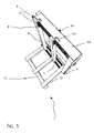
- Fig. 5 shows the illustration of Fig. 4, wherein the locking slide 101 is in a locking position.
- the locking slide 101 is displaced to the right, whereby the locking slide rests against the end face of the spars 43 and covers them approximately halfway.
- a displacement of the spars in the vertical direction is blocked upwards, so that the glass transport frame is locked in its entirety in the unfolded position.
Landscapes
- Engineering & Computer Science (AREA)
- Mechanical Engineering (AREA)
- Health & Medical Sciences (AREA)
- Public Health (AREA)
- Transportation (AREA)
- Packaging Frangible Articles (AREA)
- Pallets (AREA)
Applications Claiming Priority (1)
| Application Number | Priority Date | Filing Date | Title |
|---|---|---|---|
| DE200610017047 DE102006017047B3 (de) | 2006-04-11 | 2006-04-11 | Glastransportgestell |
Publications (1)
| Publication Number | Publication Date |
|---|---|
| EP1845041A1 true EP1845041A1 (fr) | 2007-10-17 |
Family
ID=38283958
Family Applications (1)
| Application Number | Title | Priority Date | Filing Date |
|---|---|---|---|
| EP06023244A Withdrawn EP1845041A1 (fr) | 2006-04-11 | 2006-11-08 | Rack pliable pour le transport de verre |
Country Status (2)
| Country | Link |
|---|---|
| EP (1) | EP1845041A1 (fr) |
| DE (1) | DE102006017047B3 (fr) |
Cited By (4)
| Publication number | Priority date | Publication date | Assignee | Title |
|---|---|---|---|---|
| CN109095182A (zh) * | 2018-08-31 | 2018-12-28 | 平湖市欧文洁具有限公司 | 一种淋浴房玻璃的提升输送装置 |
| US20190202598A1 (en) * | 2017-12-28 | 2019-07-04 | Dennis Ray Dickson | Easy lift rack |
| CN110482037A (zh) * | 2019-07-03 | 2019-11-22 | 中建深业建设发展有限公司 | 一种建筑工程用玻璃放置架 |
| CN112093270A (zh) * | 2020-07-28 | 2020-12-18 | 台玻悦达汽车玻璃有限公司 | 一种可拆卸玻璃放置架 |
Families Citing this family (1)
| Publication number | Priority date | Publication date | Assignee | Title |
|---|---|---|---|---|
| DE202010000112U1 (de) * | 2010-02-01 | 2011-06-01 | Weha - Ludwig Werwein GmbH, 86343 | Tranportgestell und Transportgestell-Bausatz |
Citations (5)
| Publication number | Priority date | Publication date | Assignee | Title |
|---|---|---|---|---|
| US3955676A (en) * | 1973-08-01 | 1976-05-11 | Libbey-Owens-Ford Company | Adjustable shipping rack and means for securing flat sheets thereto |
| DE10010325A1 (de) * | 2000-03-02 | 2001-09-06 | Karl Traub | Zweiteiliges Transportgestell mit aufgesetzten, einflappbaren Vorrichtungen für flächiges Transportgut |
| DE20301136U1 (de) * | 2003-01-24 | 2003-06-26 | Vetrotech Saint-Gobain (International) Ag, Bern | Transport- und Lagereinrichtung für plattenförmige Elemente |
| US20030196971A1 (en) * | 2002-04-19 | 2003-10-23 | Jeskey Marion Michael | Foldable transport rack and methods of use thereof |
| NL1026025C2 (nl) * | 2004-04-23 | 2005-10-26 | Spino Transp B V | Bok voor een binnenlader. |
Family Cites Families (3)
| Publication number | Priority date | Publication date | Assignee | Title |
|---|---|---|---|---|
| SE345430B (fr) * | 1970-04-08 | 1972-05-29 | Emmaboda Glasverk Ab | |
| NO312504B1 (no) * | 2000-08-08 | 2002-05-21 | Oeyvind Skullerud | Stötteanordning |
| DE10324358A1 (de) * | 2003-05-27 | 2004-12-16 | Fricke, Caroline | Glastransportgestell (AZL 2003 CF) mit verstellbaren Anlagen und in sich falt- und stapelbar |
-
2006
- 2006-04-11 DE DE200610017047 patent/DE102006017047B3/de not_active Expired - Fee Related
- 2006-11-08 EP EP06023244A patent/EP1845041A1/fr not_active Withdrawn
Patent Citations (5)
| Publication number | Priority date | Publication date | Assignee | Title |
|---|---|---|---|---|
| US3955676A (en) * | 1973-08-01 | 1976-05-11 | Libbey-Owens-Ford Company | Adjustable shipping rack and means for securing flat sheets thereto |
| DE10010325A1 (de) * | 2000-03-02 | 2001-09-06 | Karl Traub | Zweiteiliges Transportgestell mit aufgesetzten, einflappbaren Vorrichtungen für flächiges Transportgut |
| US20030196971A1 (en) * | 2002-04-19 | 2003-10-23 | Jeskey Marion Michael | Foldable transport rack and methods of use thereof |
| DE20301136U1 (de) * | 2003-01-24 | 2003-06-26 | Vetrotech Saint-Gobain (International) Ag, Bern | Transport- und Lagereinrichtung für plattenförmige Elemente |
| NL1026025C2 (nl) * | 2004-04-23 | 2005-10-26 | Spino Transp B V | Bok voor een binnenlader. |
Cited By (5)
| Publication number | Priority date | Publication date | Assignee | Title |
|---|---|---|---|---|
| US20190202598A1 (en) * | 2017-12-28 | 2019-07-04 | Dennis Ray Dickson | Easy lift rack |
| CN109095182A (zh) * | 2018-08-31 | 2018-12-28 | 平湖市欧文洁具有限公司 | 一种淋浴房玻璃的提升输送装置 |
| CN109095182B (zh) * | 2018-08-31 | 2024-01-05 | 平湖市欧文洁具有限公司 | 一种淋浴房玻璃的提升输送装置 |
| CN110482037A (zh) * | 2019-07-03 | 2019-11-22 | 中建深业建设发展有限公司 | 一种建筑工程用玻璃放置架 |
| CN112093270A (zh) * | 2020-07-28 | 2020-12-18 | 台玻悦达汽车玻璃有限公司 | 一种可拆卸玻璃放置架 |
Also Published As
| Publication number | Publication date |
|---|---|
| DE102006017047B3 (de) | 2007-10-31 |
Similar Documents
| Publication | Publication Date | Title |
|---|---|---|
| DE2652441C2 (de) | Verriegelungseinrichtung zum Verstauen der Fracht in einem Beförderungsmittel | |
| DE2637215A1 (de) | In der hoehe einstellbare, ortsbewegliche buehne | |
| EP2389842A1 (fr) | Elément de meuble articulé et pliant | |
| DE3436358C2 (fr) | ||
| DE202004012593U1 (de) | Vorrichtung zur Festlegung und/oder Positionierung von Gegenständen in einem Transportbehälter | |
| EP1159887B1 (fr) | Table pliable | |
| DE102006017047B3 (de) | Glastransportgestell | |
| DE102012201204B4 (de) | Verriegelungssystem für eine Tischtennisplatte | |
| DE202007002775U1 (de) | Tischmöbel mit schwenkbarer Tischplatte | |
| EP0310884B1 (fr) | Echelle repliable | |
| DE19538080A1 (de) | Transportvorrichtung für leichte Boote, Surfboards und dgl. | |
| EP0207419B1 (fr) | Boîte à outils | |
| DE3020064A1 (de) | Vorrichtung zum verriegeln der schwenkbaren eckpfosten von ladeplattformen (klappflats) | |
| EP3281826B1 (fr) | Dispositif de protection contre les chutes | |
| EP1808335A1 (fr) | Arrangement de garde-corps | |
| EP0446623A1 (fr) | Support pliant pour supporter des dessus de tables, des boîtes à outils et similaire | |
| DE2642739C3 (de) | Neigungsvorrichtung für Sitzmöbel | |
| DE20101630U1 (de) | Transport- und/oder Lagerbehälter und dafür geeigneter Einbaurahmen | |
| EP4290014B1 (fr) | Corps articulé pour une balise pliable et balise pliable | |
| DE10046512B4 (de) | Sicherungsvorrichtung zur Lagefixierung von insbesondere hochgeklappten Teilen eines Fahrzeugsitzes | |
| EP0423503A1 (fr) | Echafaudage pour le transport de verre | |
| EP2151175A2 (fr) | Table de kermesse ou banc | |
| EP3703540B1 (fr) | Comptoir de vente | |
| DE3911096A1 (de) | Werkzeugkasten od. dgl. | |
| DE202007013212U1 (de) | Klapprunge |
Legal Events
| Date | Code | Title | Description |
|---|---|---|---|
| PUAI | Public reference made under article 153(3) epc to a published international application that has entered the european phase |
Free format text: ORIGINAL CODE: 0009012 |
|
| AK | Designated contracting states |
Kind code of ref document: A1 Designated state(s): AT BE BG CH CY CZ DE DK EE ES FI FR GB GR HU IE IS IT LI LT LU LV MC NL PL PT RO SE SI SK TR |
|
| AX | Request for extension of the european patent |
Extension state: AL BA HR MK YU |
|
| 17P | Request for examination filed |
Effective date: 20071023 |
|
| 17Q | First examination report despatched |
Effective date: 20080211 |
|
| AKX | Designation fees paid |
Designated state(s): AT BE BG CH CY CZ DE DK EE ES FI FR GB GR HU IE IS IT LI LT LU LV MC NL PL PT RO SE SI SK TR |
|
| STAA | Information on the status of an ep patent application or granted ep patent |
Free format text: STATUS: THE APPLICATION IS DEEMED TO BE WITHDRAWN |
|
| 18D | Application deemed to be withdrawn |
Effective date: 20100601 |