EP1845209A1 - Zerkleinerungstoilette - Google Patents
Zerkleinerungstoilette Download PDFInfo
- Publication number
- EP1845209A1 EP1845209A1 EP20070007469 EP07007469A EP1845209A1 EP 1845209 A1 EP1845209 A1 EP 1845209A1 EP 20070007469 EP20070007469 EP 20070007469 EP 07007469 A EP07007469 A EP 07007469A EP 1845209 A1 EP1845209 A1 EP 1845209A1
- Authority
- EP
- European Patent Office
- Prior art keywords
- macerator
- toilet
- bowl
- unit
- waste
- Prior art date
- Legal status (The legal status is an assumption and is not a legal conclusion. Google has not performed a legal analysis and makes no representation as to the accuracy of the status listed.)
- Withdrawn
Links
Images




Classifications
-
- E—FIXED CONSTRUCTIONS
- E03—WATER SUPPLY; SEWERAGE
- E03D—WATER-CLOSETS OR URINALS WITH FLUSHING DEVICES; FLUSHING VALVES THEREFOR
- E03D9/00—Sanitary or other accessories for lavatories ; Devices for cleaning or disinfecting the toilet room or the toilet bowl; Devices for eliminating smells
- E03D9/10—Waste-disintegrating apparatus combined with the bowl
-
- B—PERFORMING OPERATIONS; TRANSPORTING
- B60—VEHICLES IN GENERAL
- B60R—VEHICLES, VEHICLE FITTINGS, OR VEHICLE PARTS, NOT OTHERWISE PROVIDED FOR
- B60R15/00—Arrangements or adaptations of sanitation devices
- B60R15/04—Toilet facilities
Definitions
- the present invention relates to waste management systems. More particularly, the present invention relates to macerator toilets.
- toilets In most known domestic toilets, flush water is routed directly to a drain in the floor and then to a sewage system or septic tank. Where the toilet is incorporated into a vehicle, such as a recreational vehicle, airplane, boat, train or the like, most conventional toilets route the flush water directly to an on-board holding tank.
- known toilets may incorporate a macerator.
- Such macerator toilets appear very much like conventional toilets and operate in the same manner. Rather than routing the flush water directly to a sewage system, septic tank or holding tank, however, flush water is routed to a macerator pump.
- the macerator pump is typically located in a small box that may be located on the floor between the toilet and a wall. Similar to a garbage disposal, the macerator uses fast-rotating cutting blades to substantially liquefy human waste, toilet paper and other similar materials in the flush water.
- the slurry produced by the macerator may be discharged under pressure through a discharge line to the sewage system, septic or holding tank.
- Macerating toilets advantageously permit installation that is completely above a floor. In this manner, costly excavation of the floor to install a drain line may be avoided.
- the present teachings provide a macerator toilet comprising a toilet body including a bowl portion and a base portion, the base portion defining a chamber and a macerator unit in fluid communication with the bowl portion, the macerator unit completely disposed in the chamber and operative for macerating a waste received from the bowl unit and pump the waste from the macerator toilet.
- Figure 1 is a front perspective view of a macerator toilet constructed in accordance with the present teachings, the macerator toilet shown operatively associated with a shroud for mounting of the macerator toilet proximate a corner.
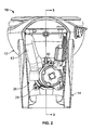
- Figure 2 is a rear view of the macerator toilet of Figure 1.
- Figure 3 is a cross-sectional view taken along the line 3-3 of Figure 2.
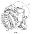
- Figure 4 is a perspective view of the macerator assembly of the toilet of Figure 1.
- Figure 5 is a top view of the macerator assembly of Figure 4.
- Figure 6 is an exploded view of the macerator assembly of Figure 4.
- Figure 7 is a perspective view of a seal member of the macerator assembly of Figure 4.
- Figure 8 is a front view of the seal member of Figure 7.
- FIGS 9 through 11 illustrate another shroud for adapting a toilet to a planar wall in accordance with the present teachings.
- a macerator toilet constructed according to the teachings of the present disclosure is illustrated and generally identified at reference character 10.
- the macerator toilet 10 is intended for use within a motor vehicle such as a recreational vehicle, boat or the like.
- the macerator toilet 10 of the present teachings provides a reduced foot print and an overall appearance substantially identical to a conventional flush toilet without a macerator.
- various teachings of the present invention allow the entire system to be contained within a conventionally shaped base without the need for an independent macerator box. Additionally, various teachings of the present invention cooperate to provide an extremely low water usage unit.
- the macerator toilet 10 of the present teachings is illustrated as a high rise toilet.
- the macerator toilet 10 may be unitarily formed to include a bowl portion 12 and a base portion 14.
- the macerator toilet 10 can be constructed as a low rise toilet that is mounted on a platform.
- the bowl portion 12 may be constructed of a vitreous china.
- the bowl portion 12 may be constructed of a vitreous china and the base portion 14 may be constructed of a plastic.
- the bowl portion 12 of the macerator toilet 10 may include an open rim 16 and a flush nozzle 18 positioned proximate a rear portion of the open rim 16.
- the bowl portion 12 may additionally include a bottom discharge outflow 20.
- the entry to the bottom discharge outflow 20 may be positioned centrally within the bowl portion 12.
- the bottom discharge outflow 20 may include a rearwardly extending portion 22.
- the rearwardly extending portion 22 may be substantially cylindrical in configuration and provide a mounting portion for coupling to a macerator unit 24.
- the bottom discharge outflow 20 may be unitarily formed with the remainder of the bowl portion 12 of vitreous china.
- the base portion 14 may support the bowl portion 12 and define a chamber 26 for housing the macerator unit 24.
- the base portion 14 may downwardly extend beyond the bottom discharge outflow 20. In alternative applications, the base portion 14 may terminate below the bottom discharge outflow 20.
- the macerator unit 24 may generally include a housing 28, an impeller pump 30 and a motor 32.
- the housing 28 may include a first housing portion 28A and a second housing portion 28B.
- the first and second housing portions 28A and 28B may cooperate to define a chamber in which the impeller pump 30 is disposed.
- a seal 34 may be captured between the first and second housing portions 28A and 28B so that the chamber is fluid tight.
- the first and second housing portions 28A and 28B may be secured to one another with a plurality of fasteners 36.
- the first housing portion 28A may define a plurality of boss portions with apertures for receiving the fasteners 36.
- the second housing portion 28B may define aligning apertures for receiving the fasteners 36.
- the fasteners 36 may be threadably received by the second housing portion 28B or may alternatively pass through the second housing portion 28B and engage nuts.
- the first housing portion 28A defines an input port 40 (see Figure 6, for example) and an output port 42.
- the input port 40 may extend at an angle to a longitudinal axis X (see Figure 5) of the macerator unit 24. The angle may be between approximately 10 and 30 degrees and may further assist In reducing the footprint of the toilet 10.
- the input port 40 may be in fluid engagement with the chamber defined by the first and second housing portions 28A and 28B and may thereby function to deliver waste to the impeller pump 30 disposed in the chamber.
- the output port 42 may similarly be in fluid communication with the chamber defined between the first and second housing portions 28A and 28B. As illustrated, the output port 42 may upwardly extend relative to the remainder of the housing 28.
- the output port 42 may carry a one-way seal 44 which presents minimal intrusion in the waste path while precluding waste from returning to the macerator unit 24.
- a suitable one-way seal 44 is further described in commonly assigned U.S. Serial No. 11/404,034 entitled “In-Line, One-Way Valve Assembly" filed contemporaneously herewith. U.S. Serial No. 11/404,034 is hereby incorporated by reference as if fully set forth herein.
- the output port 42 may be coupled to a discharge hose 43 (see Figure 2) for delivering the macerated waste to a holding tank, a sewage system or a septic tank.
- the second housing portion 28B may include a plurality of mounting portions 46 to facilitate secure attachment of the macerator unit 24 to the toilet 10.
- the second housing portion 28B may include a plurality of radially extending tabs 46.
- the plurality of radially extending tabs 46 may include three radially extending tabs 46.
- the tabs 46 may define apertures 48 for receiving fasteners 50 (see Figure 3).
- the fasteners 50 may engage mounting portions 52 (again, see Figure 3) formed with the toilet 10.
- the impeller pump 30 may be rotatably coupled to an output shaft 29 of the motor 30.
- the motor 30 may be secured to the first housing portion 28B with fasteners (not particularly shown).
- the impeller pump 30 may include plurality of blades 38 for conventionally macerating the waste.
- the plurality of blades 38 may further function in a conventional manner to direct macerated waste out the discharge port 42.
- the macerator unit 24 may be secured to the bottom discharge outflow 20 in a fluid tight manner with a seal member 54.
- the seal member 54 may be constructed of rubber or other suitable materials having the requisite strength, flexibility and durability.
- the seal member 54 may include a main body 55 (see Figure 6) that is generally cylindrical in shape and defines an inner circumferential surface 56 (see Figure 6) for receiving the input port 40 of the housing 28.
- the seal member 54 may additionally include an outer circumferential flange 58 interconnected to the main body 55. As perhaps shown most clearly in the cross-sectional view of Figure 3, the rearwardly extending portion 22 of the bottom discharge outflow 20 may be captured between the circumferential flange 58 and the main body 55.
- the flexible nature of the seal member 54 may permit mounting to the toilet 10 and the macerator unit 24 without discrete clamps and thereby reduce part count and associated labor.
- the seal member 54 may additionally include a diaphragm 60.
- the diaphragm 60 may be unitarily constructed of rubber with the remainder of the seal member 54 and may include a plurality of radially extending tabs 62.
- the tabs 62 may be configured to extend toward the housing 28.
- the diaphragm 60 may provide surge protection for the macerator unit 24.
- the tabs 62 may easily flex outwardly to allow waste to pass from the bottom discharge outflow 20 to the macerator unit 24 through an enlarged opening.
- the configuration of the tabs 62 may prevent a surge of waste from returning from the macerator unit 24 to the bottom discharge outflow 20.
- the toilet 10 may be used with a shroud 70.
- the shroud 70 may function to aesthetically interconnect the toilet 10 with one or more walls 72.
- the shroud 70 may be particularly adapted to aesthetically interconnect the toilet 10 with a corner.
- FIG. 9 An alternate shroud 72 is shown in more detail in Figures 9 through 10. It will be understood that the shroud 72 may be identical to the shroud 70 with the exception that the shroud 72 defines a generally planar rear surface 74 for abutting a single wall. A front surface 76 of the shroud 72 can be configured to matingly engage the toilet 10.
Landscapes
- Health & Medical Sciences (AREA)
- Public Health (AREA)
- Epidemiology (AREA)
- Engineering & Computer Science (AREA)
- Life Sciences & Earth Sciences (AREA)
- Hydrology & Water Resources (AREA)
- Water Supply & Treatment (AREA)
- General Health & Medical Sciences (AREA)
- Mechanical Engineering (AREA)
- Bidet-Like Cleaning Device And Other Flush Toilet Accessories (AREA)
- Crushing And Pulverization Processes (AREA)
Applications Claiming Priority (1)
| Application Number | Priority Date | Filing Date | Title |
|---|---|---|---|
| US79195306P | 2006-04-13 | 2006-04-13 |
Publications (1)
| Publication Number | Publication Date |
|---|---|
| EP1845209A1 true EP1845209A1 (de) | 2007-10-17 |
Family
ID=38222526
Family Applications (1)
| Application Number | Title | Priority Date | Filing Date |
|---|---|---|---|
| EP20070007469 Withdrawn EP1845209A1 (de) | 2006-04-13 | 2007-04-12 | Zerkleinerungstoilette |
Country Status (2)
| Country | Link |
|---|---|
| US (1) | US8276218B2 (de) |
| EP (1) | EP1845209A1 (de) |
Cited By (6)
| Publication number | Priority date | Publication date | Assignee | Title |
|---|---|---|---|---|
| US8276218B2 (en) | 2006-04-13 | 2012-10-02 | Thetford Corporation | Macerator toilet |
| WO2016088105A1 (en) * | 2014-12-05 | 2016-06-09 | Dometic Sweden Ab | Macerator toilet assembly |
| USD811562S1 (en) | 2016-11-14 | 2018-02-27 | Dometic Sweden Ab | Toilet |
| EP3406491A1 (de) * | 2017-05-04 | 2018-11-28 | Thetford BV | Toilettenteilsystem eines abwassermanagementsystems für fahrzeuge und entsprechendes verfahren |
| USD853540S1 (en) | 2017-09-18 | 2019-07-09 | Dometic Sweden Ab | Toilet lid and seat |
| AU2021257894B2 (en) * | 2018-09-27 | 2022-07-07 | Thetford Bv | Toilet Sub-System for a Wastewater Management System for Recreational Vehicles and Related Method |
Families Citing this family (11)
| Publication number | Priority date | Publication date | Assignee | Title |
|---|---|---|---|---|
| GB2453674A (en) * | 2007-05-18 | 2009-04-15 | Vernacare Ltd | A macerator having a multi-phase motor to drive blade means |
| USD654575S1 (en) | 2010-09-22 | 2012-02-21 | Thetford Corporation | Wall mounted toilet |
| USD654576S1 (en) | 2010-09-22 | 2012-02-21 | Thetford Corporation | Wall mounted bidet |
| US9340963B2 (en) | 2013-02-05 | 2016-05-17 | Bertram Y. ITO | Transportable restroom |
| US9879437B2 (en) * | 2013-02-05 | 2018-01-30 | Bertram Y. ITO | Transportable restroom |
| US9957701B2 (en) | 2013-02-05 | 2018-05-01 | Bertram Y. ITO | Roof assembly for a transportable restroom |
| US9416524B2 (en) * | 2013-03-05 | 2016-08-16 | David R. Hall | Piston-flush toilet system |
| US20210078507A1 (en) * | 2018-05-01 | 2021-03-18 | Thetford Bv | Wastewater management system for vehicles and related methods |
| WO2020033411A1 (en) | 2018-08-07 | 2020-02-13 | Kohler Co. | Toilet with non-vitreous flush engine |
| US20240401322A1 (en) * | 2021-09-08 | 2024-12-05 | As America, Inc. | Toilet Apparatus |
| JP2023039063A (ja) * | 2021-09-08 | 2023-03-20 | 株式会社Lixil | トイレ装置 |
Citations (3)
| Publication number | Priority date | Publication date | Assignee | Title |
|---|---|---|---|---|
| US3878569A (en) * | 1974-05-02 | 1975-04-22 | Itt | Sewage treatment device |
| EP1464764A1 (de) * | 2003-03-24 | 2004-10-06 | Thomas Warnecke | Toilettenanlage |
| EP1605108A1 (de) * | 2004-05-26 | 2005-12-14 | Jianhan Yada Bimetal Co. Ltd. Zheng | Nicht verstopfende WC-Schüssel |
Family Cites Families (7)
| Publication number | Priority date | Publication date | Assignee | Title |
|---|---|---|---|---|
| US3323650A (en) * | 1964-12-04 | 1967-06-06 | Jr James A Kilbane | Marine chlorinator |
| US3432108A (en) * | 1966-07-22 | 1969-03-11 | Emerson Electric Co | Flexible inlet cover |
| US5022098A (en) * | 1989-11-02 | 1991-06-11 | Richard Brower | Automatic, self-cleaning, water saving, toilet system |
| US6408448B1 (en) | 2000-04-18 | 2002-06-25 | Control Fluidics, Inc. | Water saving toilet system controller |
| US6421843B1 (en) | 2001-02-16 | 2002-07-23 | Headhunter, Inc. | Low water volume toilet |
| US6991192B2 (en) | 2003-01-07 | 2006-01-31 | Itt Manufacturing Enterprises, Inc. | Apparatus for adapting waste disposal pump to waste discharge ports of RV's, RV park systems, trains, airplanes, buses, boats and portable toilet applications, for easy and sanitary disposal of waste holding tanks |
| US8276218B2 (en) | 2006-04-13 | 2012-10-02 | Thetford Corporation | Macerator toilet |
-
2007
- 2007-04-09 US US11/697,768 patent/US8276218B2/en active Active
- 2007-04-12 EP EP20070007469 patent/EP1845209A1/de not_active Withdrawn
Patent Citations (3)
| Publication number | Priority date | Publication date | Assignee | Title |
|---|---|---|---|---|
| US3878569A (en) * | 1974-05-02 | 1975-04-22 | Itt | Sewage treatment device |
| EP1464764A1 (de) * | 2003-03-24 | 2004-10-06 | Thomas Warnecke | Toilettenanlage |
| EP1605108A1 (de) * | 2004-05-26 | 2005-12-14 | Jianhan Yada Bimetal Co. Ltd. Zheng | Nicht verstopfende WC-Schüssel |
Cited By (8)
| Publication number | Priority date | Publication date | Assignee | Title |
|---|---|---|---|---|
| US8276218B2 (en) | 2006-04-13 | 2012-10-02 | Thetford Corporation | Macerator toilet |
| WO2016088105A1 (en) * | 2014-12-05 | 2016-06-09 | Dometic Sweden Ab | Macerator toilet assembly |
| US10358809B2 (en) | 2014-12-05 | 2019-07-23 | Dometic Sweden Ab | Macerator toilet assembly |
| USD811562S1 (en) | 2016-11-14 | 2018-02-27 | Dometic Sweden Ab | Toilet |
| EP3406491A1 (de) * | 2017-05-04 | 2018-11-28 | Thetford BV | Toilettenteilsystem eines abwassermanagementsystems für fahrzeuge und entsprechendes verfahren |
| US11351935B2 (en) | 2017-05-04 | 2022-06-07 | Thetford Bv | Wastewater management system for vehicles and related methods |
| USD853540S1 (en) | 2017-09-18 | 2019-07-09 | Dometic Sweden Ab | Toilet lid and seat |
| AU2021257894B2 (en) * | 2018-09-27 | 2022-07-07 | Thetford Bv | Toilet Sub-System for a Wastewater Management System for Recreational Vehicles and Related Method |
Also Published As
| Publication number | Publication date |
|---|---|
| US8276218B2 (en) | 2012-10-02 |
| US20070240255A1 (en) | 2007-10-18 |
Similar Documents
| Publication | Publication Date | Title |
|---|---|---|
| US8276218B2 (en) | Macerator toilet | |
| EP1866201B1 (de) | Flugzeugwaschbecken mit integrierter abfallentsorgungsfunktion | |
| US6991192B2 (en) | Apparatus for adapting waste disposal pump to waste discharge ports of RV's, RV park systems, trains, airplanes, buses, boats and portable toilet applications, for easy and sanitary disposal of waste holding tanks | |
| US8529223B2 (en) | Dual diaphragm pump assembly for a sanitation system | |
| US8590068B2 (en) | Anti-overflow toilet and method | |
| US10302090B2 (en) | Bilge pump arrangement having back flow preventer | |
| CA2239434A1 (en) | Pressure flushing device discharge extension | |
| US8656524B2 (en) | Toilet assembly | |
| US20250052047A1 (en) | Waste collection and disposal system for toilets | |
| US7203976B1 (en) | Floor level waste pumping system for toilets | |
| CN115697773B (zh) | 用于储水箱且具有与储水箱的集成无泄漏接口的子组件 | |
| WO2017140942A1 (en) | Toilet arrangement | |
| US7156617B2 (en) | Dual outlet port pump | |
| US6341390B1 (en) | Plumbing trap system | |
| JP2005105581A (ja) | 圧送排水機能付き便器 | |
| EP0861981A3 (de) | Vibrationsdämpfer für Pumpsysteme Entleeren von Schiffsbehältern | |
| EP1162300A3 (de) | Entleerungsvorrichtung für Waschmaschine | |
| WO2023215968A1 (en) | Universal toilet odor removal system | |
| EP1698734A3 (de) | Leise Toilettenspülung mit geringem Wasservolumen | |
| US20230110943A1 (en) | Active ventilation system for toilet bowls | |
| CN220058227U (zh) | 节水便器的防塞结构及节水便器 | |
| JP2002275976A (ja) | 圧送装置 | |
| JP5580699B2 (ja) | 真空弁ユニット | |
| JP4255551B2 (ja) | ボルテックス型遠心ポンプにおける羽根車入口部の閉塞防止装置 | |
| US20100077543A1 (en) | Exhaustible toilet and odor removal system |
Legal Events
| Date | Code | Title | Description |
|---|---|---|---|
| PUAI | Public reference made under article 153(3) epc to a published international application that has entered the european phase |
Free format text: ORIGINAL CODE: 0009012 |
|
| AK | Designated contracting states |
Kind code of ref document: A1 Designated state(s): AT BE BG CH CY CZ DE DK EE ES FI FR GB GR HU IE IS IT LI LT LU LV MC MT NL PL PT RO SE SI SK TR |
|
| AX | Request for extension of the european patent |
Extension state: AL BA HR MK YU |
|
| 17P | Request for examination filed |
Effective date: 20080417 |
|
| 17Q | First examination report despatched |
Effective date: 20080516 |
|
| AKX | Designation fees paid |
Designated state(s): AT BE BG CH CY CZ DE DK EE ES FI FR GB GR HU IE IS IT LI LT LU LV MC MT NL PL PT RO SE SI SK TR |
|
| STAA | Information on the status of an ep patent application or granted ep patent |
Free format text: STATUS: THE APPLICATION IS DEEMED TO BE WITHDRAWN |
|
| 18D | Application deemed to be withdrawn |
Effective date: 20190704 |