EP1845218A2 - Motorbetriebene Jalousie und Verfahren zur Steuerung einer solchen - Google Patents
Motorbetriebene Jalousie und Verfahren zur Steuerung einer solchen Download PDFInfo
- Publication number
- EP1845218A2 EP1845218A2 EP07356050A EP07356050A EP1845218A2 EP 1845218 A2 EP1845218 A2 EP 1845218A2 EP 07356050 A EP07356050 A EP 07356050A EP 07356050 A EP07356050 A EP 07356050A EP 1845218 A2 EP1845218 A2 EP 1845218A2
- Authority
- EP
- European Patent Office
- Prior art keywords
- fabric
- blind
- tube
- winding
- actuator
- Prior art date
- Legal status (The legal status is an assumption and is not a legal conclusion. Google has not performed a legal analysis and makes no representation as to the accuracy of the status listed.)
- Withdrawn
Links
Images

Classifications
-
- E—FIXED CONSTRUCTIONS
- E04—BUILDING
- E04F—FINISHING WORK ON BUILDINGS, e.g. STAIRS, FLOORS
- E04F10/00—Sunshades, e.g. Florentine blinds or jalousies; Outside screens; Awnings or baldachins
- E04F10/02—Sunshades, e.g. Florentine blinds or jalousies; Outside screens; Awnings or baldachins of flexible canopy materials, e.g. canvas ; Baldachins
- E04F10/06—Sunshades, e.g. Florentine blinds or jalousies; Outside screens; Awnings or baldachins of flexible canopy materials, e.g. canvas ; Baldachins comprising a roller-blind with means for holding the end away from a building
- E04F10/0611—Sunshades, e.g. Florentine blinds or jalousies; Outside screens; Awnings or baldachins of flexible canopy materials, e.g. canvas ; Baldachins comprising a roller-blind with means for holding the end away from a building with articulated arms supporting the movable end of the blind for deployment of the blind
- E04F10/0618—Sunshades, e.g. Florentine blinds or jalousies; Outside screens; Awnings or baldachins of flexible canopy materials, e.g. canvas ; Baldachins comprising a roller-blind with means for holding the end away from a building with articulated arms supporting the movable end of the blind for deployment of the blind whereby the pivot axis of the articulation is perpendicular to the roller
-
- E—FIXED CONSTRUCTIONS
- E04—BUILDING
- E04F—FINISHING WORK ON BUILDINGS, e.g. STAIRS, FLOORS
- E04F10/00—Sunshades, e.g. Florentine blinds or jalousies; Outside screens; Awnings or baldachins
- E04F10/02—Sunshades, e.g. Florentine blinds or jalousies; Outside screens; Awnings or baldachins of flexible canopy materials, e.g. canvas ; Baldachins
- E04F10/06—Sunshades, e.g. Florentine blinds or jalousies; Outside screens; Awnings or baldachins of flexible canopy materials, e.g. canvas ; Baldachins comprising a roller-blind with means for holding the end away from a building
- E04F10/0644—Sunshades, e.g. Florentine blinds or jalousies; Outside screens; Awnings or baldachins of flexible canopy materials, e.g. canvas ; Baldachins comprising a roller-blind with means for holding the end away from a building with mechanisms for unrolling or balancing the blind
- E04F10/0651—Sunshades, e.g. Florentine blinds or jalousies; Outside screens; Awnings or baldachins of flexible canopy materials, e.g. canvas ; Baldachins comprising a roller-blind with means for holding the end away from a building with mechanisms for unrolling or balancing the blind acting on the arms
-
- E—FIXED CONSTRUCTIONS
- E04—BUILDING
- E04F—FINISHING WORK ON BUILDINGS, e.g. STAIRS, FLOORS
- E04F10/00—Sunshades, e.g. Florentine blinds or jalousies; Outside screens; Awnings or baldachins
- E04F10/02—Sunshades, e.g. Florentine blinds or jalousies; Outside screens; Awnings or baldachins of flexible canopy materials, e.g. canvas ; Baldachins
- E04F10/06—Sunshades, e.g. Florentine blinds or jalousies; Outside screens; Awnings or baldachins of flexible canopy materials, e.g. canvas ; Baldachins comprising a roller-blind with means for holding the end away from a building
- E04F10/0644—Sunshades, e.g. Florentine blinds or jalousies; Outside screens; Awnings or baldachins of flexible canopy materials, e.g. canvas ; Baldachins comprising a roller-blind with means for holding the end away from a building with mechanisms for unrolling or balancing the blind
- E04F10/0648—Sunshades, e.g. Florentine blinds or jalousies; Outside screens; Awnings or baldachins of flexible canopy materials, e.g. canvas ; Baldachins comprising a roller-blind with means for holding the end away from a building with mechanisms for unrolling or balancing the blind acting on the roller tube
-
- E—FIXED CONSTRUCTIONS
- E04—BUILDING
- E04F—FINISHING WORK ON BUILDINGS, e.g. STAIRS, FLOORS
- E04F10/00—Sunshades, e.g. Florentine blinds or jalousies; Outside screens; Awnings or baldachins
- E04F10/02—Sunshades, e.g. Florentine blinds or jalousies; Outside screens; Awnings or baldachins of flexible canopy materials, e.g. canvas ; Baldachins
- E04F10/06—Sunshades, e.g. Florentine blinds or jalousies; Outside screens; Awnings or baldachins of flexible canopy materials, e.g. canvas ; Baldachins comprising a roller-blind with means for holding the end away from a building
- E04F10/0644—Sunshades, e.g. Florentine blinds or jalousies; Outside screens; Awnings or baldachins of flexible canopy materials, e.g. canvas ; Baldachins comprising a roller-blind with means for holding the end away from a building with mechanisms for unrolling or balancing the blind
- E04F10/0659—Control systems therefor
Definitions
- the invention relates to the field of motorized solar protection, and in particular arm awnings articulated or deployable, such as terrace awnings. It relates to a motorized awning installation.
- Articulated arm awning installation generally comprises a winding tube, held at its ends in a trunk or by supports, foldable arms, awning cloth and a rigid bar called load bar.
- a tubular actuator makes it possible to motorize the installation.
- blinds generally operate on the following principle: the blind fabric is fixed by one of its sides on the winding tube inside which is the tubular actuator. This actuator rotates the tube and, therefore, allows to roll or unroll the fabric.
- the canvas is also attached on its opposite side, to the load bar. This one allows to maintain the fabric and possibly to serve as a cover to close a chest box of the blind.
- the awning arms are attached, on the one hand, to the awning box or to appropriate supports and, on the other hand, to the load bar. They have at least one elbow between two rigid sections, this elbow allowing them to bend or unfold.
- a spring held on the one hand on the section in which it is located and on the other hand, via a cable, a band or a chain, beyond the elbow, on the other rigid section. This spring is stretched during the folding of the arms.
- Arm awnings are generally deployed in a substantially horizontal manner.
- the deployment of the fabric can not therefore be achieved solely under the effect of the weight of the load bar.
- the arms tend, under the influence of the springs, to seek to unfold. Therefore, if the actuator releases the rotation of the winding tube, the fabric is driven by the arms and the blind unfolds.
- the actuator drives the winding tube in rotation, which has the effect of pulling the arms through the fabric to fold them.
- the springs of the arms generally have a high coefficient of stiffness. Indeed, it is required that the blinds classically sold on the market are unwound with the canvas tight, regardless of the stopping position, this for aesthetic and technical reasons, including the lack of water bag in case a stiffer grip and improved wind resistance.
- the tension stresses of the fabric cause in time a distension and an elongation thereof which may lead to making additional adjustments during the lifetime of the installation.
- the low end position of a blind is usually identified by a counting device.
- the arms are said to be locked, that is to say they are unfolded slightly beyond the configuration in which their rigid sections are aligned.
- the arms are then braced. This locking position allows a good maintenance of the tension of the fabric and the blind, especially with respect to the wind.
- the passage through the locking position, during deployment or more particularly the folding of the blind, requires a high drive torque between the actuator and the tube.
- the actuators for arm awnings are dimensioned for a high torque, which is generally only necessary for unlocking the arms.
- the rest of the race requires only an average couple.
- the entire blind must meet criteria of accuracy, sensitivity and tightness. Given the these criteria, the motorization of known blinds is expensive since the actuators must be powerful, typically capable of generating a torque of 25 to 120 Nm, and metering devices must be developed.
- the invention therefore seeks to solve these problems and proposes to simplify the control of the movement of a blind, while maintaining a canvas tension adapted to the market demand.
- the invention relates to a motorized blind system which comprises a winding tube, in which is disposed an actuator driving in rotation of this tube, and a load bar supported by articulated arms, a fabric of blind being secured to the load bar and adapted to be selectively wound on the winding tube.
- This installation is characterized in that it comprises means for locking at least one articulated arm in several positions corresponding to the total or partial deployment of the blind.
- the locking means allow to fix the position of the articulated arms, which ensures the consistency over time of the relative position of the load bar and the winding tube.
- this locking obtained in the different positions allows, in each of these positions, to obtain an optimized tension of the fabric.
- the fully deployed position of the blind may correspond to a configuration of the articulated arms below the configuration in which the arm sections are aligned.
- the invention finds a particularly advantageous application in the context of so-called autonomous blinds, ie operating by means of a source of energy not connected to an electrical network and possibly rechargeable, for example, thanks to photovoltaic cells or solar cells. storage batteries. Indeed, it is particularly important in this case to limit the power consumption, and therefore to limit the power required to provide the actuator during the actuation of the blind, while maintaining a sufficiently tight canvas.
- a position counter is not necessary, the blind can move between abutment points, on one side the chest and on the other a stop on the arms. This structure then simplifies the actuator which can be more easily sealed.
- the counting devices are entry points for moisture, which represents a manufacturing constraint to the extent that such a blind is placed outside. These stops can also be used to reset the position when using a manual operation in a non-power system and electronic counting.
- the method of the invention allows, thanks to the locking of the articulated arm in position, a subsequent tensioning of fabric, which allows to obtain, in all stop positions, a properly stretched canvas.
- the complementary winding of the fabric is carried out, during step b), on a predetermined angular stroke, until a predetermined fabric tension is obtained or for a predetermined duration .
- the tension of the fabric obtained during step b) is used to lock the arm during step a).
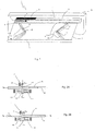
- the installation I shown in FIGS. 1 to 3 comprises a winding tube 1 disposed inside a box 2 fixed to a structure such as a wall of a B.
- a blind fabric 3 is provided to be more or less wound on the tube 1.
- the installation I also comprises two articulated and foldable arms 4, fixed on the one hand at the level of the trunk 2 and on the other hand on a load bar 5 holding the fabric 3 stretched in the direction of the width.
- the arms are formed of two rigid sections 41, for example metal, connected by a hinge 42 usually called elbow.
- At least one of the rigid sections of each arm 4 is equipped with a tensioning means 10, generally in the form of a spring tensioned during the folding of the arms 4.
- the tensioning means is fixed by a rigid fastening link. a part on the rigid section equipped with the tensioning means 10, and secondly on the second rigid section beyond the bend.
- only one of the arms 4 is provided with a tensioning means 10.
- the arms are also each equipped with a locking device 11, for locking the arms in different positions, preferably in any desired position on their deployment stroke.
- a locking device 11 is schematically represented in FIGS. 2A and 2B. This device is placed inside an arm section, for example the section 41. It acts on a first rigid axis 43 which is intercalated at the level of the rigid attachment link, between the tensioning means 10 and the elbow of the arm.
- the rigid axis undergoes displacements in translation represented by the double arrow F 2 , these displacements being coupled with the variation in length of the tensioning means 10, with respect to the arm section 41.
- the locking device being attached to the arm portion 41, when it blocks the translation of the axis rigid, a deployment of the arms under the effect of the springs is prevented.
- This device comprises a mechanical locking member 111 which defines a light 112 in which is engaged the rigid axis 43.
- the member 111 is articulated about an axis X 111 perpendicular to the longitudinal axis X 43 of the rigid axis , coinciding with the longitudinal axis X 41 of the section 41.
- the pivot support is fixed on the arm portion 41.
- the dimensions of the light 112 are such that the section 41 can slide in this light when the member 111 s' extends in a direction D 111 generally perpendicular to the axis X 43 .
- the member 111 is subjected to the action of a return spring 113 which exerts on it a force F 1 tending to tilt the member 111 about the axis X 111 , so that the direction D 111 is then no longer perpendicular to the axis X 41 .
- the member 11 blocks the displacement of the rigid axis.
- the return spring 113 is also fixed to the arm section 41.
- An electromagnet 114 is disposed in the vicinity of the member 111 which is made of a magnetic material.
- the electromagnet is dimensioned to, when active, effectively maintain the member 111 in the configuration of Figure 2A, against the force F 1 , so that the rigid axis 43 can slide in the light 112, in the direction of the double arrow F 2 in this figure.
- the member 111 switches around the axis X 11 under the effect of the force F 1 .
- the light 112 is then oriented in such a way that it blocks the sliding of the rigid axis.
- the electromagnet is also attached to the arm section 41.
- a tubular actuator 6 provided with a not shown output shaft which drives in rotation, in a first direction and in a second direction, the tube 1.
- the blocking of this output shaft for example under the action of a not shown brake, also keeps locked the winding tube.
- the actuator 6 releases at least partially the brake and therefore the rotation of the winding tube in a first direction.
- the arms 4 are forced to unfold, under the action of the tensioning means 10, driving the load bar 5 and the fabric 3.
- the tensioning means may have a relatively low stiffness constant.
- the actuator also comprises a device, internal to the actuator, monitoring 7 the torque transmitted by the actuator (motor torque) or seen by it (resistant torque). This monitoring device 7 makes it possible to indirectly monitor the tension of the fabric 3.
- the installation 1 also comprises a solar panel 8 comprising a set of photovoltaic cells and an electronic unit 9, internal to the actuator, for managing the tension of the fabric 3.
- the solar panel makes it possible to feed the actuator 6 and / or locking devices 11
- the actuator 6, or even the devices 11, can be powered from an accumulator battery, rechargeable or not.
- the actuator 6 rotates in a second direction, the winding tube 1, which has the effect of pulling on the fabric 3 and constrain the arms 4 to fold.
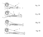
- FIGS. 3A to 3D and 4A to 4F The operating method of the installation is shown in FIGS. 3A to 3D and 4A to 4F.
- the tensioning means 10 and / or gravity cause the opening of the arms and the unwinding of the blind in the direction of the arrow F 3 in Figure 3B.
- the tensioning means 10 having a low stiffness, the fabric 3 is then relaxed.
- the devices 11 are actuated, to allow the locking of each arm 4 in position.
- the electromagnet 114 is powered, so that the member 111 takes the position of Figure 2A.
- the actuator 6 is stopped and the supply of the electromagnet 114 is cut off, so that the member 111 takes the configuration of FIG. 2B in which the portion 41 of the corresponding arm 4 is immobilized by the member 111, which represents the arrow F 4 in Figure 3c.
- Stopping the blind in the desired position can be triggered by the user or by an automatic control, for example on the basis of a position signal or on a signal from the device 7 or a sensor linked to the blind.
- the invention thus makes it possible to lock each arm 4 in any fully or partially deployed position.
- the actuator 6 automatically drives the winding tube 1 in rotation in the opposite direction, so as to tighten the fabric, as represented by the arrow F 5 in the figure 3D.
- This additional tension of the fabric 3, which is obtained by a complementary winding of this fabric on the tube 1, has the effect of exerting on the portion 41 of the arm 4 a force F 6 which, as shown in FIG. accumulates with the force F 2 due to the spring 113 to bring the member 111 into a blocking position of the portion 41.
- the tension of the fabric itself can, via the F force 6 , activate the locking device 111.
- the process is applied in reverse order. Again, in the open initial position shown in FIG. 4A, the arms are locked, which represents the arrow F 4 , and the blind fabric is stretched.
- the actuator drives the winding tube in a first direction of rotation in the direction of the arrow F 7 so as to relax the fabric 3 and mechanically release the arms 4, as shown in Figure 4B .
- the device 11 is then unlocked, which represents the arrow F ' 4 in Figure 4C, then the actuator drives the winding tube in a second direction, that of the arrow F 8 , so as to wind the fabric and fold the arms, as shown in Figure 4D.
- monitoring is put in place to stop this decline when a threshold is reached.
- the criterion monitored in this step by the unit 9 may be an actuation time, an angle of rotation or a torque. When a predetermined value of the monitored criterion has been reached, the complementary winding of the fabric 3 is stopped.
- the monitored criterion can be defined during a learning process.
- the fabric 3 is then slightly stretched.
- the actuator is stopped, which represents Figure 4E.
- the locking devices 11 are then activated, which represents the arrow F 4 in Figure 4F.
- the actuator then drives the fabric again in the direction of the arrow F 10 , to stretch more strongly and mechanically lock the arms.
- the actuator When the fabric is under mechanical tension or when the awning is completely closed, for example for a sealed closure of a trunk, the actuator must provide a peak torque, but this on a small displacement and with a speed very weak.
- DC motor actuator in place of an asynchronous motor is particularly advantageous.
- DC motors are indeed capable of operating at nominal speed with good efficiency but can also provide a closing torque well above the nominal torque.
- the actuator 6 advantageously comprises a not shown electro-brake capable of holding this closing torque.
- the invention has been shown with a particular type of locking device shown in FIGS. 2A and 2B.
- This device 11 has the advantage of limiting the power consumption of the electromagnet 114 which must be powered only when the arm 4 on which it acts is being deployed or folded.
- locking systems may be envisaged, including fully mechanical systems, self-locking type according to the direction of movement imparted by the actuator.
- Other electromechanical locking systems are also conceivable.
- the tension of the fabric activates the locking device 11 or equivalent. Indeed, this device can be controlled independently of the effort F 6 . On the contrary, the locking device can be controlled only by this force, especially if it is a totally mechanical self-locking device.
- the locking member, 111 or equivalent, of the locking device 11 can act directly on one of the sections 41 of the arm 4 or a locking latch of the arm.
- the invention is also applicable in the case where only one of the arms 4 is equipped with a locking device 11.
Landscapes
- Engineering & Computer Science (AREA)
- Architecture (AREA)
- Civil Engineering (AREA)
- Structural Engineering (AREA)
- Building Awnings And Sunshades (AREA)
Applications Claiming Priority (1)
| Application Number | Priority Date | Filing Date | Title |
|---|---|---|---|
| FR0603353A FR2899924A1 (fr) | 2006-04-14 | 2006-04-14 | Installation de store motorisee et procede de commande d'une telle installation |
Publications (2)
| Publication Number | Publication Date |
|---|---|
| EP1845218A2 true EP1845218A2 (de) | 2007-10-17 |
| EP1845218A3 EP1845218A3 (de) | 2007-11-14 |
Family
ID=37669622
Family Applications (1)
| Application Number | Title | Priority Date | Filing Date |
|---|---|---|---|
| EP07356050A Withdrawn EP1845218A3 (de) | 2006-04-14 | 2007-04-13 | Motorbetriebene Jalousie und Verfahren zur Steuerung einer solchen |
Country Status (3)
| Country | Link |
|---|---|
| US (1) | US20070240832A1 (de) |
| EP (1) | EP1845218A3 (de) |
| FR (1) | FR2899924A1 (de) |
Cited By (1)
| Publication number | Priority date | Publication date | Assignee | Title |
|---|---|---|---|---|
| EP2453073A1 (de) * | 2010-11-16 | 2012-05-16 | Meunier, Stéphane | Motorbetriebene Markise mit Fotovoltaik-Solarstromantrieb |
Families Citing this family (14)
| Publication number | Priority date | Publication date | Assignee | Title |
|---|---|---|---|---|
| FR2899923B1 (fr) * | 2006-04-14 | 2009-02-06 | Somfy Sas | Procede de commande et installation de store commandee par ce procede |
| FR2923508B1 (fr) * | 2007-11-13 | 2009-12-25 | Somfy Sas | Procede de fonctionnement d'un actionneur electromecanique pour store a bras |
| FR2940812B1 (fr) * | 2009-01-06 | 2011-02-11 | Somfy Sas | Procede de fonctionnement d'une installation domotique de protection solaire motorisee |
| US8161990B1 (en) * | 2010-07-01 | 2012-04-24 | Coletta Anthony J | Clothesline cover apparatus |
| US9047758B2 (en) | 2013-03-14 | 2015-06-02 | Dometic Corporation | Solar powered energy module |
| US9469997B2 (en) | 2013-12-12 | 2016-10-18 | Carefree/Scott Fetzer Company | Lateral arm awning system and method of operation |
| US10947736B2 (en) | 2016-03-25 | 2021-03-16 | Carefree/Scott Fetzer Company | Residential awning canopy assembly |
| US20170275884A1 (en) | 2016-03-25 | 2017-09-28 | Carefree/Scott Fetzer Company | Residential awning canopy assembly |
| IT201700090501A1 (it) * | 2017-08-04 | 2019-02-04 | Teleco Automation Srl | Dispositivo di controllo delle luci di una tenda avvolgibile motorizzata |
| US10313141B1 (en) * | 2018-03-09 | 2019-06-04 | Elbex Video Ltd. | Method and a tester for testing and verifying the conductivity of optical cable segments linked within a cascaded infrastructure of smart residences |
| US10560050B2 (en) * | 2018-06-15 | 2020-02-11 | Evolusun, Inc. | Innovative energy generating photovoltaic awning |
| US20230028387A1 (en) * | 2021-07-20 | 2023-01-26 | Lippert Components Manufacturing, Inc. | Rv awning systems and related methods |
| AU2024219094A1 (en) * | 2023-02-10 | 2025-08-14 | Scott Fetzer/Carefree Of Colorado | Fail-safe awning and method of making same |
| CN118756856B (zh) * | 2024-09-05 | 2024-11-22 | 山西建筑工程集团有限公司 | 一种alc轻质隔墙板插入式连接装置 |
Family Cites Families (3)
| Publication number | Priority date | Publication date | Assignee | Title |
|---|---|---|---|---|
| FR2164099A5 (de) * | 1971-12-10 | 1973-07-27 | Calamuso Joseph | |
| FR2481355A1 (fr) * | 1980-04-29 | 1981-10-30 | Franciaflex | Store du type banne a bras motorises |
| DE9208343U1 (de) * | 1992-06-23 | 1993-10-28 | Hüppe Form Sonnenschutz- und Raumtrennsysteme GmbH, 26133 Oldenburg | Markise |
-
2006
- 2006-04-14 FR FR0603353A patent/FR2899924A1/fr active Pending
-
2007
- 2007-04-13 EP EP07356050A patent/EP1845218A3/de not_active Withdrawn
- 2007-04-13 US US11/785,069 patent/US20070240832A1/en not_active Abandoned
Cited By (2)
| Publication number | Priority date | Publication date | Assignee | Title |
|---|---|---|---|---|
| EP2453073A1 (de) * | 2010-11-16 | 2012-05-16 | Meunier, Stéphane | Motorbetriebene Markise mit Fotovoltaik-Solarstromantrieb |
| FR2967450A1 (fr) * | 2010-11-16 | 2012-05-18 | Meunier Stephane Rene Andre Paul | Store d'exterieur motorise a alimentation photovoltaique |
Also Published As
| Publication number | Publication date |
|---|---|
| US20070240832A1 (en) | 2007-10-18 |
| EP1845218A3 (de) | 2007-11-14 |
| FR2899924A1 (fr) | 2007-10-19 |
Similar Documents
| Publication | Publication Date | Title |
|---|---|---|
| EP1845218A2 (de) | Motorbetriebene Jalousie und Verfahren zur Steuerung einer solchen | |
| EP1845217B1 (de) | Verfahren zur Steuerung und Installation einer durch dieses Verfahren gesteuerten Jalousie | |
| EP0619413B1 (de) | Motorangetriebener Rolladen | |
| EP3325753B1 (de) | Vorrichtung zum aufwickeln einer abschirmung mit einer scharnierwandbefestigung | |
| WO2012085252A1 (fr) | Dispositif motorise de manoeuvre destine a la manoeuvre d'un ecran mobile a toile enroulable d'un dispositif de couverture de fenetre ou d'ecran de projection | |
| FR2588307A1 (fr) | Dispositif d'ecran motorise | |
| EP3341551B1 (de) | Heimautomationsanlage zum verschliessen oder zum sonnenschutz und verfahren zum aufladen einer batterie für solch eine anlage | |
| EP0645518A1 (de) | Getrieb- und Unterspannungsetzungsvorrichtung eines biegsamen Schutzelements wie eines Bandes, eines Vorhangs oder eines Schürze | |
| CA2754398A1 (fr) | Dispositif de protection solaire de type store muni d'un systeme de production d'energie electrique | |
| FR2570119A1 (fr) | Dispositif de deroulement et d'enroulement d'une surface souple sur un tube | |
| FR2969224A1 (fr) | Eolienne verticale repliable et deployable selon differentes hauteurs | |
| FR2740824A1 (fr) | Installation de fermeture ou de protection solaire motorisee | |
| EP1093947B1 (de) | Motorisiertes Fensterrollo, mit selektiver Kupplunsvorrichtung zwischen Aufwickelrohr und Motorantrieb | |
| EP1331354A1 (de) | Rolladen mit Gurtbetätigung und Vorrichting gegen das Hochschieben | |
| EP3263822B1 (de) | Haustechnikanlage | |
| EP0676514A1 (de) | Schattierungs- und/oder Abdunkelungseinrichtung mit einer biegsamen Membran | |
| FR2588037A1 (fr) | Volet roulant de protection pour ouverture horizontale, ou de faible pente ou a contre pente, dans les toitures | |
| EP4033053B1 (de) | Automatische ein- und aufrollvorrichtung einer plane über der beckenoberfläche eines pools | |
| FR3053720B1 (fr) | Store a lames orientables | |
| EP2199486A1 (de) | Planenrollo vom Typ Kastenrollo | |
| FR3087474A1 (fr) | Procede de controle d'un systeme d'actionnement d'un premier et d'un second ecrans et systeme d'actionnement | |
| FR3087473A1 (fr) | Systeme motorise pour une ouverture de batiment et procede de motorisation d'un dispositif d'ecran escamotable | |
| EP3470617B1 (de) | Automatisiertes steuerverfahren einer rollladenanlage und rollladenanlage | |
| FR2968727A1 (fr) | Eolienne verticale repliable a envergure modulable | |
| EP3394367A1 (de) | Teleskopische einheit zur lagerung eines abdeckelements in einem lagerraum |
Legal Events
| Date | Code | Title | Description |
|---|---|---|---|
| PUAI | Public reference made under article 153(3) epc to a published international application that has entered the european phase |
Free format text: ORIGINAL CODE: 0009012 |
|
| PUAL | Search report despatched |
Free format text: ORIGINAL CODE: 0009013 |
|
| AK | Designated contracting states |
Kind code of ref document: A2 Designated state(s): AT BE BG CH CY CZ DE DK EE ES FI FR GB GR HU IE IS IT LI LT LU LV MC MT NL PL PT RO SE SI SK TR |
|
| AX | Request for extension of the european patent |
Extension state: AL BA HR MK YU |
|
| AK | Designated contracting states |
Kind code of ref document: A3 Designated state(s): AT BE BG CH CY CZ DE DK EE ES FI FR GB GR HU IE IS IT LI LT LU LV MC MT NL PL PT RO SE SI SK TR |
|
| AX | Request for extension of the european patent |
Extension state: AL BA HR MK YU |
|
| 17P | Request for examination filed |
Effective date: 20080324 |
|
| AKX | Designation fees paid |
Designated state(s): AT BE BG CH CY CZ DE DK EE ES FI FR GB GR HU IE IS IT LI LT LU LV MC MT NL PL PT RO SE SI SK TR |
|
| STAA | Information on the status of an ep patent application or granted ep patent |
Free format text: STATUS: THE APPLICATION HAS BEEN WITHDRAWN |
|
| 18W | Application withdrawn |
Effective date: 20090318 |