EP1845259A1 - Pompe à commande magnétique - Google Patents
Pompe à commande magnétique Download PDFInfo
- Publication number
- EP1845259A1 EP1845259A1 EP07007363A EP07007363A EP1845259A1 EP 1845259 A1 EP1845259 A1 EP 1845259A1 EP 07007363 A EP07007363 A EP 07007363A EP 07007363 A EP07007363 A EP 07007363A EP 1845259 A1 EP1845259 A1 EP 1845259A1
- Authority
- EP
- European Patent Office
- Prior art keywords
- magnetic
- drive
- pump
- inductor
- rotational shaft
- Prior art date
- Legal status (The legal status is an assumption and is not a legal conclusion. Google has not performed a legal analysis and makes no representation as to the accuracy of the status listed.)
- Granted
Links
- 238000005192 partition Methods 0.000 claims abstract description 15
- 239000002826 coolant Substances 0.000 claims description 33
- 230000004044 response Effects 0.000 claims description 6
- 239000012530 fluid Substances 0.000 claims description 2
- 230000006903 response to temperature Effects 0.000 claims 1
- XLYOFNOQVPJJNP-UHFFFAOYSA-N water Substances O XLYOFNOQVPJJNP-UHFFFAOYSA-N 0.000 description 15
- 230000004907 flux Effects 0.000 description 10
- 230000006698 induction Effects 0.000 description 6
- 239000000696 magnetic material Substances 0.000 description 6
- 238000010276 construction Methods 0.000 description 5
- 239000000446 fuel Substances 0.000 description 5
- 230000005540 biological transmission Effects 0.000 description 4
- 230000002093 peripheral effect Effects 0.000 description 4
- 230000007423 decrease Effects 0.000 description 2
- 239000000411 inducer Substances 0.000 description 2
- 238000010792 warming Methods 0.000 description 2
- 239000004020 conductor Substances 0.000 description 1
- 239000000203 mixture Substances 0.000 description 1
- 230000000717 retained effect Effects 0.000 description 1
- 238000007789 sealing Methods 0.000 description 1
- 238000004904 shortening Methods 0.000 description 1
- 230000001502 supplementing effect Effects 0.000 description 1
Images



Classifications
-
- F—MECHANICAL ENGINEERING; LIGHTING; HEATING; WEAPONS; BLASTING
- F04—POSITIVE - DISPLACEMENT MACHINES FOR LIQUIDS; PUMPS FOR LIQUIDS OR ELASTIC FLUIDS
- F04D—NON-POSITIVE-DISPLACEMENT PUMPS
- F04D13/00—Pumping installations or systems
- F04D13/02—Units comprising pumps and their driving means
- F04D13/021—Units comprising pumps and their driving means containing a coupling
-
- F—MECHANICAL ENGINEERING; LIGHTING; HEATING; WEAPONS; BLASTING
- F04—POSITIVE - DISPLACEMENT MACHINES FOR LIQUIDS; PUMPS FOR LIQUIDS OR ELASTIC FLUIDS
- F04D—NON-POSITIVE-DISPLACEMENT PUMPS
- F04D13/00—Pumping installations or systems
- F04D13/02—Units comprising pumps and their driving means
- F04D13/021—Units comprising pumps and their driving means containing a coupling
- F04D13/022—Units comprising pumps and their driving means containing a coupling a coupling allowing slip, e.g. torque converter
-
- F—MECHANICAL ENGINEERING; LIGHTING; HEATING; WEAPONS; BLASTING
- F04—POSITIVE - DISPLACEMENT MACHINES FOR LIQUIDS; PUMPS FOR LIQUIDS OR ELASTIC FLUIDS
- F04D—NON-POSITIVE-DISPLACEMENT PUMPS
- F04D13/00—Pumping installations or systems
- F04D13/02—Units comprising pumps and their driving means
- F04D13/021—Units comprising pumps and their driving means containing a coupling
- F04D13/024—Units comprising pumps and their driving means containing a coupling a magnetic coupling
- F04D13/027—Details of the magnetic circuit
-
- F—MECHANICAL ENGINEERING; LIGHTING; HEATING; WEAPONS; BLASTING
- F04—POSITIVE - DISPLACEMENT MACHINES FOR LIQUIDS; PUMPS FOR LIQUIDS OR ELASTIC FLUIDS
- F04D—NON-POSITIVE-DISPLACEMENT PUMPS
- F04D15/00—Control, e.g. regulation, of pumps, pumping installations or systems
- F04D15/02—Stopping of pumps, or operating valves, on occurrence of unwanted conditions
Definitions
- the present invention relates to a magnetic drive pump which drives an impeller to rotate by magnetic force.
- a known magnetic drive pump described in JP2005-139917A discloses a water pump which includes an impeller rotatably supported in a pump chamber so as to generate a flow of the fluid in the pump chamber by the rotation thereof and a drive mechanism which rotates the impeller.
- the drive mechanism includes a permanent magnet integrally fixed to a drive magnet rotatably positioned outside relative to a partition wall which separates the pump chamber from the outside, and an inductor including a conductor which is rotated by the induced current generated by the rotation of the permanent magnet.
- the water pump i.e., the magnetic drive pump
- a flow rate of the coolant i.e., workload of the pump
- the workload of the pump during high engine rotation speed can be appropriately set compared to the conventional water pump in which a flow rate of the coolant increases linearly.
- the present invention provides a magnetic drive pump, which includes a pump chamber including a path having an inlet port and an outlet port; a partition wall separating the pump chamber from an exterior, a rotational shaft provided at a side of the pump chamber relative to the partition wall, an impeller rotatably supported by a first end of the rotational shaft, an inductor integrally fixed to the impeller to rotate, a magnetic means positioned radially outside of the partition wall and facing the inductor, the magnetic means rotatably supported, a rotation drive means fixed to the magnetic means and actuating the magnetic means to rotate, and a drive means moving at least one of the magnetic, means and the inductor in an axial direction of the rotational shaft.
- the magnetic force generated between the magnetic means and the inductor can be controlled. Namely, during the engine cold starting and warming up when the temperature of the coolant is low, rotation speed of the impeller which rotates integrally with the inductor is reduced by reducing the magnetic force generated between the magnetic means and the inductor, the rise time of the coolant temperature is shortened by reducing the flow rate of the coolant, and the engine load is reduced to improve the fuel economy.
- Fig. 1 is a cross-sectional view of a magnetic drive pump according to a first embodiment of the present invention.
- Fig. 2 is a cross-sectional view showing a modified example according to the first embodiment of the present invention.
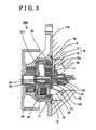
- Fig. 3 is a cross-sectional view of a magnetic drive pump according to a second embodiment of the present invention.
- Fig. 4 is a view showing an example of operational pattern of the magnetic drive pump according to the first embodiment of the present invention.
- a water pump (i.e., serving as a magnetic drive pump) 100 is fixed to an engine block 9 by means of a fastening means.
- the water pump 100 includes an inlet port 7 and an outlet port 8 which are formed on the engine block 9, a body 110 which defines a pump chamber 10 by covering a recessed portion 9a formed on the engine block 9, an impeller 15 which is supported so as to rotate in the pump chamber 10 and to generate a flow of coolant in the pump chamber 10 by the rotation thereof, and a drive mechanism 50 which drives the impeller 15 to rotate.
- a rotation shaft 13 is fixed to a partition wall 12 made from a non-magnetic material, which separates the pump chamber 10 formed at the engine block 9 from an outside portion (i.e., serving as exterior) 11.
- the impeller 15 is pivotally supported by the rotation shaft 13.
- a core 16, which is made from laminated plates, is integrally fixed to a backside of the impeller 15.
- the core 16 and an induction ring 17 form an inductor 18.
- a permanent magnet (i.e., serving as a magnetic means) 20 is positioned radially outside of the inductor 18 facing the inducer 18 intervened by the partition wall 12 therebetween.
- the permanent magnet 20 is divided into pieces in a circumferential direction and the north poles and the south poles are arranged alternately.
- the permanent magnet 20 is fixed to an inner periphery of a ring shaped yoke 26, which is made from magnetic material, and is integrally formed with a cylindrical diaphragm 19 formed stepwise to have a shaft portion in the center thereof.
- the diaphragm 19 is made from non-magnetic material and is retained by an outer cylinder 21, which is formed stepwise, in a state where the diaphragm 19 is slidable in an axial direction.
- the diaphragm 19 and the outer cylinder 21 form a hermetically closed space (i.e., serving as a drive means) 23 which is configured to be airtight by a sealing member 22 provided on a sliding surface of the yoke 26.
- a stopper 14 made from magnetic material is fixed to an open end of the outer cylinder 21 at a side of the impeller 15 so as to restrict the position of the permanent magnet 20 in an axial direction.
- the stopper 14 is arranged so as to contact with the yoke 26 to restrict the position of the permanent magnet 20 in the axial direction.
- a center 16a of the core 16 in an axial direction is offset by a predetermined degree towards the impeller 15 relative to a center 20a of the permanent magnet 20.
- the outer cylinder 21 includes a stepped shaft portion which has a smaller diameter at an opposite side of the impeller 15.
- a pulley (i.e., serving as a rotation drive means) 24 is integrally fixed onto the shaft portion of the outer cylinder 21.
- a vacuum pressure connector 25 is provided at an end of a bottom portion of the stepped shaft portion of the outer cylinder 21 via a bearing 27 which has the air tightness.
- the vacuum pressure connector 25 is connected to a vacuum pump 42, which is a vacuum source, via a vacuum pressure control valve 41. Alternatively, manifold air pressure of the engine may be used as the vacuum source.
- An upper portion of a view in Fig. 1 shows a state of the water pump 100 where the vacuum pressure is not applied to the hermetically closed space 23 and a bottom portion of the view in Fig. 1 shows a state of the water pump 100 where the vacuum pressure is applied to the hermetically closed space 23.
- the permanent magnet 20 is attracted to be biased to the core 16 by the magnetic force so that the yoke 26 contacts the stopper 14. Because the stopper 14 and the yoke 16 are made from magnetic material, the stopper 14 and the yoke 16 attract each other by the magnetic force.
- the outer cylinder 21 and the diaphragm 19 integrally rotate and a direction of magnetic flux between the permanent magnet 20 provided at the internal peripheral surface of the diaphragm 19 and inductor 18 changes in accordance with the rotation.
- the vacuum pressure is not applied to the hermetically closed state 23 (See the upper portion of the view in Fig. 1)
- the flux volume affecting between the permanent magnet 20 provided at the internal peripheral surface of the diaphragm 19 and the inductor 18 is maximized, the induced current generated at the inducer 18 by the changes of the magnetic flux direction is maximized, which maximizes the magnetic force, and thus a transmission torque by the magnetic induction is maximized. Accordingly, the rotational force of the impeller 15 is maximized to maximize the discharge performance of the pump.
- a spring 28 which biases the diaphragm 19 towards the impeller 15 for supplementing the attraction between the permanent magnet 20 and the core 16, may be provided in the hermetically closed space 23.
- the discharge performance of the pump is maximized without applying the vacuum pressure to the hermetically closed space 23.
- the vacuum pressure is applied to the hermetically closed space 23 to move the diaphragm 19 in the axial direction so as to reduce the excessive coolant flow and thus to reduce the drive force.
- an engine control computer outputs a control signal to a vacuum pressure control valve on the basis of an engine rotation speed, the temperature of coolant, and throttle opening degree to control the vacuum pressure, and thus to optimally control the flow rate of the coolant to be constantly the minimum degree necessary.
- the vacuum pressure control valve may be controlled to repeat an operated state (i.e., ON time) and a non-operated state (i.e., OFF time) alternately within an arbitrary period in accordance with necessary flow rate, and an average flow rate within a predetermined time may be controlled.
- Fig. 4 shows an example of the foregoing alternative control. For example, by controlling the ON time to be 30 percent, 50 percent, or 80 percent of a predetermined time of 5-10 second cycle, an average flow rate within the predetermined time can be controlled to be 30 percent, 50 percent, or 80 percent of the maximum flow rate respectively.
- warm-up of the engine can be quickly achieved by reducing the flow rate of the coolant during engine cold starting and warm up, and simultaneously, output of unnecessary power is reduced to improve the fuel economy.
- FIG. 3 A water pump (i.e., serving as a magnetic drive pump) 200 is shown in Fig. 2. The same reference number is provided to the identical construction with the first embodiment and the explanation is not repeated.
- a cylindrical shaft 30 is fixed to a partition wall 12 which is made from non-magnetic material and is configured to separate a pump chamber 10 formed inside an engine block 9 from an outer portion 11.
- Thermowax i.e., serving as a drive means; serving as a thermally actuated member; serving as a thermosensitive drive portion
- a slider 31 which supports a rod 33 configured to slide therein is provided in the shaft 30 so as to slide therein.
- a rotational shaft 133 is outfitted on an external periphery of the shaft 30 so as to slide in the axial direction.
- An impeller 15 is pivotally supported by the rotational shaft 133 via a bearing 14.
- the thermowax 32 expands, the slider 31 is pushed in an axial direction by the rod 33 which is in contact with the partition wall 12, and the rotational shaft 133 is pushed in the axial direction by a pin 35 which protrudes from the slider 31 in a radial direction.
- the core 16 and an induction ring 17 form an inductor 18.
- a permanent magnet (i.e., serving as a magnetic means) 20 is provided on an internal periphery of an outer cylinder 211 which is shaped in a cylinder having a bottom.
- the permanent magnet 20 is arranged radially outside of the inductor 18 intervened by the partition wall 12 therebetween.
- the outer cylinder 211 includes a stepped shaft portion at a bottom portion to which a pulley (i.e., serving as a rotation drive means) 24 is integrally fixed.
- An upper portion of a view in Fig. 2 shows a state of the water pump 200 where the coolant temperature is high and a bottom portion of the view in Fig. 2 shows a state of the water pump 200 where the coolant temperature is low.
- the outer cylinder 211 Upon a rotation of the pulley 24 by a rotation drive force transmitted from an engine via a belt, the outer cylinder 211 rotates and the direction of the magnetic flux between the permanent magnet 20 provided at the internal peripheral surface of the outer cylinder 211 and the inductor 18 changes.
- the slider 31 In a state where the temperature of the coolant is low, the slider 31 is positioned closer to the pulley 24 because the thermowax 32 is contracted. In this state, because the rotational shaft 133 is also biased by the coil spring 34 towards the pulley 24, the inductor 18 and the permanent magnet 20 are positioned so as not to face each other and the flux volume affecting between the permanent magnet 20 and the inductor 18 is minimized, the induced current generated at the inductor 18 by the changes of the flux direction is reduced, and thus the transmission torque by the magnetic induction is lowered. Namely, in the state where the temperature of the coolant is low, the rotational force of the impeller 15 is reduced to lower the discharge performance of the pump.
- thermowax 32 expands to move the slider 31 towards the engine block 9 in an axial direction. Because the pin 35 protruded from the slider 31 in the radial direction pushes the rotational shaft 133 towards the engine block 9 in the axial direction against a biasing force of the coil spring 34, the inductor 18 is moved along with the rotational shaft 133 to come to the position facing the permanent magnet 20. In those circumstances, the flux volume affecting between the inductor 18 and the permanent magnet 20 is maximized, the induced current generated at the inductor 18 by the change of the flux direction is maximized, which maximizes the magnetic force, and thus the transmission torque by the magnetic induction is maximized. Simultaneously, because the distance d between the tip end of the impeller 15 and the engine block 9 is minimized to maximize the discharge volume of the pump 200, the engine can be appropriately cooled by adequate amount of coolant.
- the magnetic force generated between the magnetic means and the inductor can be controlled. Namely, during the engine cold starting and warming up when the temperature of the coolant is low, rotation speed,of the impeller which rotates integrally with the inductor is reduced by reducing the magnetic force generated between the magnetic means and the inductor, the rise time of the coolant temperature is shortened by reducing the flow rate of the coolant, and the engine load is reduced to improve the fuel economy.
- the drive means includes the hermetically closed space which changes volume in response to a change of internal pressure applied thereto, at least one of the magnetic means or the inductor can be moved by a simple structure, and the magnetic force generated between the magnetic means and the inductor can be controlled.
- At least one of the magnetic means or the inductor can be moved by the vacuum pressure, and the magnetic force generated between the magnetic means and the inductor can be controlled.
- an optimum discharge volume by the pump is controlled in accordance with the states such as warmed-up state of the engine and states such as load applied to the engine.
- thermosensitive drive member which is provided in the rotational shaft and expands and contracts in response to the temperature of the coolant, in the drive means, a flow rate of the coolant can be controlled based on the temperature of the coolant.
- thermosensitive drive member by including the thermally actuated member and the elastic member in the thermosensitive drive member, a flow rate of the coolant can be controlled with a simple structure.
Landscapes
- Engineering & Computer Science (AREA)
- Mechanical Engineering (AREA)
- General Engineering & Computer Science (AREA)
- Structures Of Non-Positive Displacement Pumps (AREA)
Applications Claiming Priority (3)
| Application Number | Priority Date | Filing Date | Title |
|---|---|---|---|
| JP2006109401 | 2006-04-12 | ||
| JP2006298329 | 2006-11-02 | ||
| JP2007081275A JP5217204B2 (ja) | 2006-04-12 | 2007-03-27 | 磁力駆動式ポンプ |
Publications (2)
| Publication Number | Publication Date |
|---|---|
| EP1845259A1 true EP1845259A1 (fr) | 2007-10-17 |
| EP1845259B1 EP1845259B1 (fr) | 2011-03-16 |
Family
ID=38441611
Family Applications (1)
| Application Number | Title | Priority Date | Filing Date |
|---|---|---|---|
| EP07007363A Ceased EP1845259B1 (fr) | 2006-04-12 | 2007-04-10 | Pompe à commande magnétique |
Country Status (2)
| Country | Link |
|---|---|
| US (1) | US7922464B2 (fr) |
| EP (1) | EP1845259B1 (fr) |
Families Citing this family (8)
| Publication number | Priority date | Publication date | Assignee | Title |
|---|---|---|---|---|
| US20100193594A1 (en) * | 2004-12-20 | 2010-08-05 | Edc Automotive, Llc | Electronic thermostat |
| JP4999157B2 (ja) * | 2006-12-28 | 2012-08-15 | アネスト岩田株式会社 | 磁気カップリングを介して駆動源に結合した流体機械 |
| JP4297946B2 (ja) * | 2007-03-20 | 2009-07-15 | トヨタ自動車株式会社 | 圧力動作機構及び該圧力動作機構を備えるウォータポンプ |
| JP2009097412A (ja) * | 2007-10-16 | 2009-05-07 | Aisin Seiki Co Ltd | 磁力駆動式ポンプ |
| ATE540209T1 (de) * | 2010-01-11 | 2012-01-15 | Pierburg Pump Technology Gmbh | Mechanische verbrennungsmotor-kühlmittelpumpe |
| US9511178B2 (en) * | 2012-07-09 | 2016-12-06 | Medtronic, Inc. | Reducing centrifugal pump bearing wear through dynamic magnetic coupling |
| BR112021005291A2 (pt) * | 2018-09-20 | 2021-06-22 | Phaanix Pty Ltd | geração de energia |
| CN114837792A (zh) | 2021-03-10 | 2022-08-02 | 美普盛(上海)汽车零部件有限公司 | 一种带膨胀补偿密封件的电动冷却液泵 |
Citations (6)
| Publication number | Priority date | Publication date | Assignee | Title |
|---|---|---|---|---|
| US3411450A (en) * | 1967-03-07 | 1968-11-19 | Little Giant Corp | Pump |
| JPS60170476A (ja) * | 1984-02-14 | 1985-09-03 | Daido Steel Co Ltd | 磁気駆動装置 |
| US5066200A (en) * | 1990-05-17 | 1991-11-19 | Ansimag, Inc. | Double containment pumping system for pumping hazardous materials |
| EP0512516A1 (fr) * | 1991-05-08 | 1992-11-11 | Koyo Seiko Co., Ltd. | Dispositif d'entraînement magnétique |
| US20040131485A1 (en) * | 2003-01-08 | 2004-07-08 | Assoma Inc. | Sealed magnetic drive sealless pump |
| US6997688B1 (en) * | 2003-03-06 | 2006-02-14 | Innovative Mag-Drive, Llc | Secondary containment for a magnetic-drive centrifugal pump |
Family Cites Families (3)
| Publication number | Priority date | Publication date | Assignee | Title |
|---|---|---|---|---|
| US2230717A (en) * | 1939-10-24 | 1941-02-04 | Gilbert & Barker Mfg Co | Pumping means |
| FR1492184A (fr) * | 1966-06-27 | 1967-08-18 | Eurotechni Office | Dispositif de ventilation destiné au refroidissement d'un moteur thermique |
| JP2005139917A (ja) * | 2003-11-04 | 2005-06-02 | Aisin Seiki Co Ltd | 磁力駆動式ポンプ |
-
2007
- 2007-04-10 US US11/783,576 patent/US7922464B2/en not_active Expired - Fee Related
- 2007-04-10 EP EP07007363A patent/EP1845259B1/fr not_active Ceased
Patent Citations (6)
| Publication number | Priority date | Publication date | Assignee | Title |
|---|---|---|---|---|
| US3411450A (en) * | 1967-03-07 | 1968-11-19 | Little Giant Corp | Pump |
| JPS60170476A (ja) * | 1984-02-14 | 1985-09-03 | Daido Steel Co Ltd | 磁気駆動装置 |
| US5066200A (en) * | 1990-05-17 | 1991-11-19 | Ansimag, Inc. | Double containment pumping system for pumping hazardous materials |
| EP0512516A1 (fr) * | 1991-05-08 | 1992-11-11 | Koyo Seiko Co., Ltd. | Dispositif d'entraînement magnétique |
| US20040131485A1 (en) * | 2003-01-08 | 2004-07-08 | Assoma Inc. | Sealed magnetic drive sealless pump |
| US6997688B1 (en) * | 2003-03-06 | 2006-02-14 | Innovative Mag-Drive, Llc | Secondary containment for a magnetic-drive centrifugal pump |
Also Published As
| Publication number | Publication date |
|---|---|
| US20070243085A1 (en) | 2007-10-18 |
| US7922464B2 (en) | 2011-04-12 |
| EP1845259B1 (fr) | 2011-03-16 |
Similar Documents
| Publication | Publication Date | Title |
|---|---|---|
| EP1845259B1 (fr) | Pompe à commande magnétique | |
| KR100841272B1 (ko) | 유체 마찰식 클러치 | |
| US6837193B2 (en) | Flow control valve | |
| EP2055910B1 (fr) | Pompe à eau | |
| JP4614848B2 (ja) | 電子制御式流体継手装置 | |
| JP4117791B2 (ja) | 電磁駆動式流体摩擦クラッチ | |
| JP2006136088A (ja) | 電動モータ及び電動圧縮機 | |
| US7690335B2 (en) | Water pump and control method for same | |
| GB2346676A (en) | Electromagnetically controlled fan viscous clutch | |
| KR101983519B1 (ko) | 외부 제어식 팬·클러치 장치 | |
| JP5217204B2 (ja) | 磁力駆動式ポンプ | |
| JP4062485B2 (ja) | マグネット式ファンクラッチ装置 | |
| US20090097996A1 (en) | Magnetic drive pump | |
| JP2007138717A (ja) | ウォータポンプ | |
| JP2017115944A (ja) | 流量制御弁 | |
| EP1529960A1 (fr) | Pompe à entraínement magnétique | |
| JPS62210287A (ja) | ウオ−タポンプ | |
| JP2007120645A (ja) | 外部制御式流体継手 | |
| CN217462334U (zh) | 一种具有两级回油结构的电控硅油离合器 | |
| JP2001349278A (ja) | 可変容量圧縮機用制御弁 | |
| JP4293418B2 (ja) | マグネット式ファンクラッチ装置 | |
| JPH0133714B2 (fr) | ||
| JP2009185726A (ja) | ウォーターポンプ | |
| CN102792029A (zh) | 机械式冷却液泵 | |
| CN222991758U (zh) | 热管理水泵组件、热管理集成装置以及车辆 |
Legal Events
| Date | Code | Title | Description |
|---|---|---|---|
| PUAI | Public reference made under article 153(3) epc to a published international application that has entered the european phase |
Free format text: ORIGINAL CODE: 0009012 |
|
| AK | Designated contracting states |
Kind code of ref document: A1 Designated state(s): AT BE BG CH CY CZ DE DK EE ES FI FR GB GR HU IE IS IT LI LT LU LV MC MT NL PL PT RO SE SI SK TR |
|
| AX | Request for extension of the european patent |
Extension state: AL BA HR MK YU |
|
| RIN1 | Information on inventor provided before grant (corrected) |
Inventor name: SAKUMOTO, TAKASHIC/O INTELLECTUAL PROPERTY DEPARTM Inventor name: ADACHI, KAZUNARIC/O INTELLECTUAL PROPERTY DEPARTME |
|
| AKX | Designation fees paid | ||
| 17P | Request for examination filed |
Effective date: 20080125 |
|
| RBV | Designated contracting states (corrected) |
Designated state(s): CZ DE FR |
|
| GRAP | Despatch of communication of intention to grant a patent |
Free format text: ORIGINAL CODE: EPIDOSNIGR1 |
|
| RIN1 | Information on inventor provided before grant (corrected) |
Inventor name: SAKUMOTO, TAKASHIC/O INTELLECTUAL PROPERTY DEPARTM Inventor name: ADACHI, KAZUNARIC/O INTELLECTUAL PROPERTY DEPARTME |
|
| GRAS | Grant fee paid |
Free format text: ORIGINAL CODE: EPIDOSNIGR3 |
|
| GRAA | (expected) grant |
Free format text: ORIGINAL CODE: 0009210 |
|
| AK | Designated contracting states |
Kind code of ref document: B1 Designated state(s): CZ DE FR |
|
| REF | Corresponds to: |
Ref document number: 602007013133 Country of ref document: DE Date of ref document: 20110428 Kind code of ref document: P |
|
| REG | Reference to a national code |
Ref country code: DE Ref legal event code: R096 Ref document number: 602007013133 Country of ref document: DE Effective date: 20110428 |
|
| PG25 | Lapsed in a contracting state [announced via postgrant information from national office to epo] |
Ref country code: CZ Free format text: LAPSE BECAUSE OF FAILURE TO SUBMIT A TRANSLATION OF THE DESCRIPTION OR TO PAY THE FEE WITHIN THE PRESCRIBED TIME-LIMIT Effective date: 20110316 |
|
| PLBE | No opposition filed within time limit |
Free format text: ORIGINAL CODE: 0009261 |
|
| STAA | Information on the status of an ep patent application or granted ep patent |
Free format text: STATUS: NO OPPOSITION FILED WITHIN TIME LIMIT |
|
| 26N | No opposition filed |
Effective date: 20111219 |
|
| REG | Reference to a national code |
Ref country code: DE Ref legal event code: R097 Ref document number: 602007013133 Country of ref document: DE Effective date: 20111219 |
|
| REG | Reference to a national code |
Ref country code: FR Ref legal event code: PLFP Year of fee payment: 10 |
|
| REG | Reference to a national code |
Ref country code: FR Ref legal event code: PLFP Year of fee payment: 11 |
|
| REG | Reference to a national code |
Ref country code: FR Ref legal event code: PLFP Year of fee payment: 12 |
|
| PGFP | Annual fee paid to national office [announced via postgrant information from national office to epo] |
Ref country code: FR Payment date: 20200312 Year of fee payment: 14 |
|
| PGFP | Annual fee paid to national office [announced via postgrant information from national office to epo] |
Ref country code: DE Payment date: 20200331 Year of fee payment: 14 |
|
| REG | Reference to a national code |
Ref country code: DE Ref legal event code: R119 Ref document number: 602007013133 Country of ref document: DE |
|
| PG25 | Lapsed in a contracting state [announced via postgrant information from national office to epo] |
Ref country code: FR Free format text: LAPSE BECAUSE OF NON-PAYMENT OF DUE FEES Effective date: 20210430 Ref country code: DE Free format text: LAPSE BECAUSE OF NON-PAYMENT OF DUE FEES Effective date: 20211103 |