EP1845294A2 - Soupape de commutation guidée pneumatique de deuxième étage - Google Patents
Soupape de commutation guidée pneumatique de deuxième étage Download PDFInfo
- Publication number
- EP1845294A2 EP1845294A2 EP07106122A EP07106122A EP1845294A2 EP 1845294 A2 EP1845294 A2 EP 1845294A2 EP 07106122 A EP07106122 A EP 07106122A EP 07106122 A EP07106122 A EP 07106122A EP 1845294 A2 EP1845294 A2 EP 1845294A2
- Authority
- EP
- European Patent Office
- Prior art keywords
- housing
- valve seat
- piston
- section
- poppet
- Prior art date
- Legal status (The legal status is an assumption and is not a legal conclusion. Google has not performed a legal analysis and makes no representation as to the accuracy of the status listed.)
- Withdrawn
Links
- 230000008878 coupling Effects 0.000 claims abstract description 9
- 238000010168 coupling process Methods 0.000 claims abstract description 9
- 238000005859 coupling reaction Methods 0.000 claims abstract description 9
- 239000000463 material Substances 0.000 claims description 6
- -1 polytetrafluoroethylene Polymers 0.000 claims description 3
- 239000007769 metal material Substances 0.000 claims description 2
- 229920001721 polyimide Polymers 0.000 claims description 2
- 239000009719 polyimide resin Substances 0.000 claims description 2
- 229920000642 polymer Polymers 0.000 claims description 2
- 229920001343 polytetrafluoroethylene Polymers 0.000 claims description 2
- 239000004810 polytetrafluoroethylene Substances 0.000 claims description 2
- BFKJFAAPBSQJPD-UHFFFAOYSA-N tetrafluoroethene Chemical group FC(F)=C(F)F BFKJFAAPBSQJPD-UHFFFAOYSA-N 0.000 claims description 2
- 229920001169 thermoplastic Polymers 0.000 claims description 2
- 239000004416 thermosoftening plastic Substances 0.000 claims description 2
- 238000004891 communication Methods 0.000 description 10
- 239000000446 fuel Substances 0.000 description 6
- 238000011144 upstream manufacturing Methods 0.000 description 6
- 238000002485 combustion reaction Methods 0.000 description 4
- 230000004044 response Effects 0.000 description 3
- 239000012530 fluid Substances 0.000 description 2
- 230000002093 peripheral effect Effects 0.000 description 2
- 230000000712 assembly Effects 0.000 description 1
- 238000000429 assembly Methods 0.000 description 1
- 238000001816 cooling Methods 0.000 description 1
- 230000003628 erosive effect Effects 0.000 description 1
- 230000007246 mechanism Effects 0.000 description 1
- 238000000034 method Methods 0.000 description 1
- 230000004048 modification Effects 0.000 description 1
- 238000012986 modification Methods 0.000 description 1
- 230000037361 pathway Effects 0.000 description 1
- 230000008569 process Effects 0.000 description 1
- 238000007789 sealing Methods 0.000 description 1
Images
Classifications
-
- F—MECHANICAL ENGINEERING; LIGHTING; HEATING; WEAPONS; BLASTING
- F16—ENGINEERING ELEMENTS AND UNITS; GENERAL MEASURES FOR PRODUCING AND MAINTAINING EFFECTIVE FUNCTIONING OF MACHINES OR INSTALLATIONS; THERMAL INSULATION IN GENERAL
- F16K—VALVES; TAPS; COCKS; ACTUATING-FLOATS; DEVICES FOR VENTING OR AERATING
- F16K31/00—Actuating devices; Operating means; Releasing devices
- F16K31/12—Actuating devices; Operating means; Releasing devices actuated by fluid
- F16K31/42—Actuating devices; Operating means; Releasing devices actuated by fluid by means of electrically-actuated members in the supply or discharge conduits of the fluid motor
- F16K31/423—Actuating devices; Operating means; Releasing devices actuated by fluid by means of electrically-actuated members in the supply or discharge conduits of the fluid motor the actuated members consisting of multiple way valves
Definitions
- the present invention relates to a gas turbine engine and, more particularly, to a system for guiding a valve used in a two stage pneumatic switching valve.
- a gas turbine engine may be used to supply power to various types of vehicles and systems, including, for example, an aircraft.
- Many gas turbine engines include at least one or more compressor sections, a combustor section, and a turbine section.
- the one or more compressor sections receive a flow of intake air and raise the pressure of this air to a relatively high level.
- the air then enters the combustor section where fuel nozzles inject a steady stream of fuel thereto, and the injected fuel is ignited by a burner.
- the energy of the compressed air is sufficiently increased, the high-energy compressed air then flows into and through the turbine section, causing rotationally mounted turbine blades to rotate and generate energy.
- the gas turbine engine may also be used to supply either, or both, electrical and pneumatic power to the aircraft.
- Some gas turbine engines include a bleed air port between the compressor section and the turbine section which diverts a portion of the compressed air from the compressor section to various aircraft systems and/or components.
- the bleed air may be used in aircraft cabin cooling systems, deicing systems, or simply bled overboard to assist in engine starting and surge protection.
- the flow of the bleed air is governed by one or more bleed valves that are controlled by one or more control valves, such as a switching valve assembly.
- the two stage switching valve assembly includes a three-way solenoid valve that operates a second stage, three-way pneumatic amplifier, such as a poppet valve.
- the solenoid valve is adapted to receive a current and, in response, opens or closes to respectively allow or prevent bleed air flow through it.
- the poppet valve in response to the flow of bleed air through the solenoid valve, slides back and forth through a cylinder-like housing to engage either an upper valve seat or a lower valve seat, and thereby control bleed air delivery.
- bleed air is prevented from flowing to various aircraft systems and/or components.
- the poppet engages the lower valve seat bleed air is allowed to flow to the various aircraft systems and/or components.
- the poppet may abrade the housing and cause wear and erosion thereof.
- surfaces of the poppet and/or the housing may become rough or galled, preventing the poppet from moving smoothly through the housing.
- the poppet may become misaligned relative to the housing seating surfaces.
- the present invention provides a bleed air control valve system.
- the system includes a housing, a piston, a cap, a poppet, a first guide ring, and a second guide ring.
- the housing includes a first end, a second end, and an inner surface having an upper valve seat extending radially inwardly therefrom.
- the piston is located at least partially in the housing proximate the housing first end, and the piston is configured to move axially through the housing between a first position and a second position.
- the cap is coupled to the housing second end and includes a plate and an annular axial section extending therefrom. The annular axial section is located in the housing second end and has a lower valve seat formed thereon.
- the poppet is located at least partially within the housing downstream of the piston and includes a piston coupling section, a valve body section, and a guide section, the piston coupling section coupled to the piston, the valve body section including an outer surface having an upper valve seat contact surface and a lower valve seat contact surface extending radially outwardly therefrom, the upper valve seat contact surface contacting the upper valve seat when the piston is in the first position, the lower valve seat contact surface contacting the lower valve seat when the piston is in the second position, and the guide section extending through the cap annular axial section.
- the first guide ring is coupled to the piston and extends radially outwardly therefrom contacting the housing inner surface.
- the second guide ring is coupled to the poppet guide section and extends radially outwardly therefrom contacting the cap annular axial section.
- a control valve for controlling air flow in a system including an inlet and an outlet.
- the control valve includes a solenoid, a ball pilot valve, a housing, a piston, a cap, a poppet, a first guide ring, and a second guide ring.
- the solenoid is adapted to receive a current.
- the ball pilot valve assembly is in communication with the solenoid and located between the inlet and the outlet. The ball pilot valve assembly is movable when the solenoid receives the current between at least (i) a closed position, in which the inlet is not in fluid communication with the outlet, and (ii) an open position, in which the inlet is in fluid communication with the outlet allowing the air to flow therebetween.
- the housing includes a first end, a second end, and an inner surface, and the housing inner surface defines a chamber in communication with the outlet and has an upper valve seat extending radially inwardly therefrom.
- the piston is located at least partially in the housing proximate the housing first end and has an upstream side and a downstream side.
- the piston upstream end is configured to receive the air from the outlet and to cause the piston to move, in response thereto, axially through the housing between a first position and a second position.
- the cap is coupled to the housing second end and includes a plate and an annular axial section extending therefrom.
- the annular axial section is located in the housing second end and has an annular end defining a lower valve seat thereon.
- the poppet is located at least partially within the housing downstream of the piston and includes a piston coupling section, a valve body section, and a guide section, where the piston coupling section is coupled to the piston downstream side, the valve body section includes an outer surface having an upper valve seat contact surface and a lower valve seat contact surface extending radially outwardly therefrom, the upper valve seat contact surface contacts the upper valve seat when the piston is in the first position and the lower valve seat contact surface contacting the lower valve seat when the piston is in the second position, and the guide section extends through the cap annular axially extending section.
- the first guide ring is coupled to the piston and extending radially outwardly therefrom to contact the housing inner surface.
- the second guide ring is coupled to the poppet guide section and extends radially outwardly therefrom to contact the cap annular axially extending section.
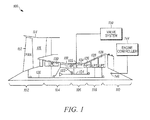
- FIG. 1 is a simplified schematic of an exemplary multi-spool turbofan gas turbine engine
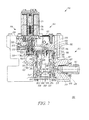
- FIG. 2 is a cross section of an exemplary switching valve system that may be implemented in the engine depicted in FIG. 1.
- FIG. 1 A simplified representation of an exemplary multi-spool turbofan gas turbine jet engine 100 is depicted in FIG. 1, and includes an intake section 102, a compressor section 104, a combustion section 106, a turbine section 108, and an exhaust section 110.
- the intake section 102 includes a fan 112, which is mounted in a fan case 114.
- the fan 112 draws air into the intake section 102 and accelerates it.
- a fraction of the accelerated air exhausted from the fan 112 is directed through a bypass section 116 (shown only partially in FIG. 1) located between the fan case 114 and an engine case 118, and provides a forward thrust.
- the remaining fraction of air exhausted from the fan 112 is directed into the compressor section 104.
- the compressor section 104 includes two compressors, a low pressure compressor 120, and a high pressure compressor 122.
- the low pressure compressor 120 raises the pressure of the air directed into it from the fan 112, and directs the compressed air into the high pressure compressor 122.
- the high pressure compressor 122 compresses the air still further, and directs the high pressure air into the combustion section 106.
- a bleed air port 125 is located downstream if the high pressure compressor 122 and is configured to bleed a portion of the compressed air to various channels leading to other sections of the aircraft. Regulation of bleed air flow is governed by a switching valve system 150, which will be discussed in more detail below.
- the combustion section 106 which includes a combustor 124, a plurality of non-illustrated fuel injectors, and one or more non-illustrated igniters, the high pressure air is mixed with fuel and combusted. The combusted air is then directed into the turbine section 108.
- the turbine section 108 includes two turbines, a high pressure turbine 126 and a low pressure turbine 128, located in axial flow series in the engine case 118.
- the combusted air from the combustion section 106 expands through each turbine 126, 128, causing each to rotate.
- the air is then exhausted through a propulsion nozzle located in the exhaust section 110, providing addition forward thrust.
- each drives equipment in the engine 100 via concentrically located shafts or spools.
- the low pressure turbine 128 drives the fan 112 and the low pressure compressor 120 via a low pressure spool 136
- the high pressure turbine 126 drives the high pressure compressor 122 via a high pressure spool 134.
- the overall operation of the engine 100 is controlled via an engine controller 144.
- the engine controller 144 as is generally known, is used to control the output power of the engine 100 by, for example, controlling fuel flow rate to the engine 100, and controlling airflow through the engine 100.
- the engine controller 144 also controls the flow of turbine bleed air from the engine 100 to various sections of the aircraft for starting the main engine, controlling the aircraft environment, controlling cabin pressure, and/or de-icing the aircraft.
- the engine controller 144 receives signals from a plurality of sensors 146 that are located at various locations on and within the engine 100.
- the sensors 146 are used to sense various physical parameters associated with the engine 100 such as, for example, various temperatures, engine speed, and air flow, and supply signals representative of the sensed parameters to the engine controller 144.
- the engine controller 144 processes the signals received from the sensors 146 and, among other things, supplies various commands to various components of the engine 100 to control its operation. It will be appreciated that the engine controller 144 may be any one of numerous types of engine controllers such as, for example, a FADEC (Full Authority Digital Engine Controller).
- FADEC Full Authority Digital Engine Controller
- the switching valve system 150 governs the flow of bleed air.
- the switching valve system 150 is coupled to the engine controller 144 and selectively bleeds and directs some of the air discharged from the compressor section 104 to one or more sections of the aircraft via a downstream channel 168.
- FIG. 2 shows an exemplary switching valve system 150, which includes a bleed air conduit system 152 that is coupled to a two stage solenoid-activated control system 154.
- the bleed air conduit system 152 receives bleed air from the bleed air port 125 and includes an inlet 158, a first stage outlet 160, a second stage outlet 162 and first and second stage channels 164, 166 that fluidly couple the inlet 158 and outlets 160, 162 together, respectively.
- the two stage solenoid-activated control system 154 includes a first stage solenoid valve assembly 170 and a second stage poppet valve assembly 172.
- the two assemblies 170, 172 cooperate to substantially instantaneously supply or prevent bleed air flow upon receiving appropriate commands from, for example, the engine controller 144.
- the first stage solenoid valve assembly 170 is in flow communication with the first stage channel 164 to receive air from the inlet 158, and includes a solenoid 174, an actuator 176, and a ball pilot valve 178.
- the solenoid 174 is electrically coupled to receive current from a non-illustrated energy source which may receive energize/de-energize commands from the engine controller 144.
- the energized solenoid 174 causes the actuator 176 to move.
- the ball pilot valve 178 is coupled to the actuator 176 and includes at least a portion that is configured to move into and out of the first stage outlet 160.
- the second stage poppet valve assembly 172 fluidly communicates with the first stage solenoid valve assembly 170 via a valve connector channel 177 and with the bleed air conduit system 152 via the second stage channel 166.
- the second stage poppet valve assembly 172 includes a housing 180, a piston 182, a poppet 184, an upper and a lower valve seat 186, 188, and two guide rings 190, 192.
- the housing 180 is preferably at least substantially cylindrical and has an inner surface 194 that defines an upper chamber 196 and a lower chamber 197.
- a valve opening 198 formed in the housing 180 provides communication between the upper chamber 196 and the valve connector channel 177, while one or more bleed air openings 200 formed downstream of the valve opening 198 provides communication between the upper chamber 196 and the bleed air conduit system 152.
- the housing 180 also includes one or more main outlets 202 and a vent outlet 203 formed therein to provide communication between the lower chamber 197 and the downstream channel 168 and ambient environment 199, respectively.
- the vent outlet 203 is covered with a cap 204 to prevent debris that may be present in the ambient environment 199 from entering the poppet valve assembly 172 and hampering functional operation.
- the cap 204 includes a plate 206 having a plurality of apertures 208 formed therein and an annular axial section 212 that extends from the plate 206 into the lower chamber 197.
- the end of the annular axial section 212 includes the lower valve seat 188 formed thereon.
- the lower valve seat 188 may be formed on the housing inner surface 194 in the lower chamber 197 and may extend radially inwardly therefrom.
- the upper valve seat 186 is located between the upper and lower chambers 196, 197 and is also configured to selectively contact a portion of the poppet 184.
- the upper valve seat 186 extends radially inwardly from the housing inner surface 194 forming an annular flange thereon.
- the piston 182 is located between the valve opening 198 and upper valve seat 186 and is configured to slidably move therebetween.
- the piston 182 is generally disk-shaped and has an upstream side 216 in communication with the bleed air and a downstream side 218.
- the downstream side 218 is coupled to the poppet 184 which may be fastened thereto in any one of numerous fashions.
- a dynamic seal 220 may be located around the outer peripheral surface of the piston 182 to at least substantially prevent bleed air leakage through the poppet valve assembly 172.
- the piston 182 and a substantially closed upstream end 222 of the poppet 184 each include fastener openings 224, 226 formed therein through which a bolt 228 is threaded.
- the bolt 228 forms a leaktight seal with the piston 182 to prevent air from flowing through the fastener openings 224, 226.
- washers 230, 232, or other sealing mechanisms are located in the fastener openings 224, 226.
- the poppet 184 extends from the piston 182 through the housing 180 and includes a piston coupling section 234, a valve body section 236, and a guide section 238.
- the valve body section 236 extends between the housing upper valve seat 186 and the housing outlet 202 and has an outer surface 240 from which an upstream and a lower valve seat contact surface 242, 244 extend radially outward. It will be appreciated that the upper valve seat contact surface 242 is configured to contact the upper valve seat 186, while the lower valve seat contact surface 244 is configured to contact against the lower valve seat 188. In some embodiments, such as shown in FIG. 2, each of the valve seats 186, 214 and valve seat contact surfaces 242, 244 are chamfered to reduce wear caused by repeated contact therebetween.
- the guide section 238 prevents the components of the second stage poppet valve assembly 172 from becoming misaligned and extends at least partially through the annular axial section 212 of the cap 204.
- the guide rings 190, 192 are included.
- the guide rings 190, 192 are preferably made of non-metallic material that is different than the materials from which the housing 180, piston 182, poppet 184, and cap 204 are made, and that is wear and friction resistant.
- suitable materials include various wear resistant, low friction thermoplastics such as, for example, polytetrafluoroethylene, filled tetrafluoroethylene polymers, polyetheretheketones, and filled polyimide resins.
- one guide ring 190 is located on the outer peripheral surface of the piston 182 to thereby maintain a predetermined distance between the piston 182 and the housing inner surface 194, while the other guide ring 192 is coupled to an outer surface of the guide section 238 to maintain the poppet 184 and the cap annular axial section 212 spaced apart a predetermined distance from one another.
- the guide section 238 may be configured to provide additional pathways for the bleed air to travel when the poppet 184 is unseated from the lower valve seat 188.
- openings 246 may be included in the guide section 238 that are formed between the lower valve seat contact surface 244 and downstream end 248 of the poppet 184.
- bleed air enters the bleed air conduit system inlet 158. Because the solenoid 174 is de-energized, the actuator 176 moves the ball pilot valve 178 into the first stage outlet 160 preventing bleed air flow through the first stage solenoid valve assembly 170. The bleed air does, however, flow into the second stage poppet valve assembly 172. In particular, the bleed air travels through the second stage outlet 162 through one or more of the bleed air openings 200 of the housing 180 and exerts pressure against the downstream side 218 of the piston 182 to maintain the piston 182 in a first, closed position.
- the upper valve seat contact surface 242 contacts the upper valve seat 186 preventing the bleed air from flowing to the downstream channel 168.
- the solenoid 174 moves the actuator 176, which, in turn, lifts the ball pilot valve 178 out of the first stage outlet 160 allowing the bleed air conduit system inlet 158 and the second stage housing valve opening 198 to fluidly communication with one another. Consequently, bleed air flows through the first stage channel 164 and the valve connector channel 177 to the second stage poppet valve assembly 172.
- bleed air in the first stage solenoid assembly 170 is vented through a non-illustrated vent, the ball pilot valve 178 returns to a position to block the first stage outlet 160, and the upper valve seat contact surface 242 seats against the upper valve seat 186.
- a residual amount of bleed air may be present in the downstream channel 168 and may need to be vented.
- the bleed air reenters the lower chamber 197 of the housing 180 and because the lower valve seat contact surface 244 is unseated from the lower valve seat 188, the air is able to flow therearound and to exit into the ambient environment 199 via the cap plate apertures 208.
- the guide rings 190, 192 prevent the piston 182, poppet 184, and housing 180 from abrading. Additionally, the guide rings 190, 192, in conjunction with the poppet guide section 238, maintain the piston 182 and poppet 184 aligned within the housing 180.
Landscapes
- Engineering & Computer Science (AREA)
- General Engineering & Computer Science (AREA)
- Mechanical Engineering (AREA)
- Fluid-Driven Valves (AREA)
- Multiple-Way Valves (AREA)
Applications Claiming Priority (1)
| Application Number | Priority Date | Filing Date | Title |
|---|---|---|---|
| US11/404,327 US20070241297A1 (en) | 2006-04-13 | 2006-04-13 | Guided pneumatic second stage switching valve |
Publications (2)
| Publication Number | Publication Date |
|---|---|
| EP1845294A2 true EP1845294A2 (fr) | 2007-10-17 |
| EP1845294A3 EP1845294A3 (fr) | 2008-06-11 |
Family
ID=38179767
Family Applications (1)
| Application Number | Title | Priority Date | Filing Date |
|---|---|---|---|
| EP07106122A Withdrawn EP1845294A3 (fr) | 2006-04-13 | 2007-04-13 | Soupape de commutation guidée pneumatique de deuxième étage |
Country Status (2)
| Country | Link |
|---|---|
| US (1) | US20070241297A1 (fr) |
| EP (1) | EP1845294A3 (fr) |
Cited By (1)
| Publication number | Priority date | Publication date | Assignee | Title |
|---|---|---|---|---|
| WO2008132426A1 (fr) * | 2007-04-25 | 2008-11-06 | Rolls-Royce Plc | Ensemble de contrôle d'un écoulement de liquide vers un composant de moteur à turbine à gaz |
Families Citing this family (2)
| Publication number | Priority date | Publication date | Assignee | Title |
|---|---|---|---|---|
| US8011382B2 (en) * | 2008-10-06 | 2011-09-06 | Honeywell International Inc. | Bi-modal bleed valve assembly for gas turbine engine |
| US11008949B2 (en) | 2018-09-25 | 2021-05-18 | Pratt & Whitney Canada Corp. | Multi-source air system and switching valve assembly for a gas turbine engine |
Citations (2)
| Publication number | Priority date | Publication date | Assignee | Title |
|---|---|---|---|---|
| US3126915A (en) | 1964-03-31 | Fluid control valve | ||
| US20050044858A1 (en) | 2003-08-26 | 2005-03-03 | Kenneth Hooker | Two stage solenoid control valve |
Family Cites Families (31)
| Publication number | Priority date | Publication date | Assignee | Title |
|---|---|---|---|---|
| US3043335A (en) * | 1953-04-20 | 1962-07-10 | Int Basic Economy Corp | Fluid control valve |
| US3063467A (en) * | 1960-04-08 | 1962-11-13 | Mission Mfg Co | Valve seats |
| DE1750758B1 (de) * | 1968-05-31 | 1971-03-11 | Herion Werke Kg | Mehrwegewntil mit haupt und hilfsventil und rueckstellung des hilfsventils |
| DE2424148C2 (de) * | 1974-05-17 | 1983-08-11 | Robert Bosch Gmbh, 7000 Stuttgart | Gasdichtes Ventil für Maschinen zur Behandlung von Materialien mit hohen Temperatur- und Druckstößen |
| HU174165B (hu) * | 1974-06-26 | 1979-11-28 | Walter Hunger | Napravljajuhhij i uplotnjajuhhij mekhanizm k porshnjam, shatunam i podobnym detaljam |
| US3921660A (en) * | 1974-08-15 | 1975-11-25 | Marotta Scientific Controls | Three-way, two-position non-interflow poppet valve |
| US4165762A (en) * | 1978-02-21 | 1979-08-28 | International Telephone And Telegraph Corporation | Latching valve |
| US4267862A (en) * | 1979-02-21 | 1981-05-19 | Mac Valves, Inc. | Directional control valve with flow path through valve spool |
| US4257572A (en) * | 1979-02-22 | 1981-03-24 | Mac Valves, Inc. | Valve with internal accumulator and check valve |
| US4567914A (en) * | 1981-08-03 | 1986-02-04 | General Electric Company | Two-stage hydraulic solenoid valve |
| DK148757C (da) * | 1981-09-22 | 1986-02-17 | B & W Diesel As | Udstoedsventil til en stempelforbraendingsmotor |
| US4527781A (en) * | 1983-08-08 | 1985-07-09 | General Motors Corporation | Pneumatic vehicle suspension unit with air sleeve guide |
| US4802621A (en) * | 1986-09-25 | 1989-02-07 | Consolidated Controls Corporation | Thermal modulating control valve |
| DE3700899A1 (de) * | 1987-01-14 | 1988-07-28 | Herion Werke Kg | Wegeventil |
| FR2619884B1 (fr) * | 1987-08-25 | 1990-01-12 | Brev Ind Marine Exploit | Soupape de securite pilotee |
| US4971115A (en) * | 1989-07-27 | 1990-11-20 | Humphrey Products Company | Four-way poppet valve with hollow stem and four-port body |
| JPH03199789A (ja) * | 1989-12-28 | 1991-08-30 | Aisin Aw Co Ltd | 電磁弁 |
| US5347915A (en) * | 1991-11-06 | 1994-09-20 | Maschinenfabrik Sulzer-Burckhardt Ag | Piston compressor for the oilfree compression of gases |
| US5474816A (en) * | 1993-04-16 | 1995-12-12 | The Regents Of The University Of California | Fabrication of amorphous diamond films |
| US5341723A (en) * | 1993-04-20 | 1994-08-30 | Michael Hung | Reciprocating pneumatic motor for hydraulics |
| US5450782A (en) * | 1994-08-03 | 1995-09-19 | Westinghouse Air Brake Company | Vibration desensitizing piston wear ring for railroad car control valve |
| DE9415921U1 (de) * | 1994-10-04 | 1996-02-01 | Martin Merkel GmbH & Co KG, 21107 Hamburg | Führungsanordnung für Hydraulikzylinder |
| AU1080297A (en) * | 1995-11-13 | 1997-06-05 | Wilkerson Corporation | Slow start supply and exhaust valve |
| JP2001501283A (ja) * | 1997-07-30 | 2001-01-30 | ローベルト ボツシユ ゲゼルシヤフト ミツト ベシユレンクテル ハフツング | ピストンポンプ |
| FR2784719B1 (fr) * | 1998-10-15 | 2002-09-06 | Bosch Gmbh Robert | Pompe a piston |
| US6209582B1 (en) * | 2000-05-26 | 2001-04-03 | Honeywell Commercial Vehicle Systems Company | 2-way collar and O-ring seal assembly |
| DE10042716A1 (de) * | 2000-08-31 | 2002-03-14 | Mannesmann Rexroth Ag | Entsperrbares Rückschlagventil für sehr hohe Systemdrücke |
| JP4779232B2 (ja) * | 2001-05-25 | 2011-09-28 | 株式会社アドヴィックス | 車両制動装置 |
| FR2830310B1 (fr) * | 2001-09-28 | 2005-03-18 | Zf Sachs Ag | Segment de piston a etancheite renforcee notamment pour le piston d'un amortisseur |
| US20030151018A1 (en) * | 2002-02-13 | 2003-08-14 | Nobutaka Teshima | Solenoid valve |
| JP4175106B2 (ja) * | 2002-12-25 | 2008-11-05 | 大日本印刷株式会社 | 液体充填バルブ |
-
2006
- 2006-04-13 US US11/404,327 patent/US20070241297A1/en not_active Abandoned
-
2007
- 2007-04-13 EP EP07106122A patent/EP1845294A3/fr not_active Withdrawn
Patent Citations (2)
| Publication number | Priority date | Publication date | Assignee | Title |
|---|---|---|---|---|
| US3126915A (en) | 1964-03-31 | Fluid control valve | ||
| US20050044858A1 (en) | 2003-08-26 | 2005-03-03 | Kenneth Hooker | Two stage solenoid control valve |
Cited By (2)
| Publication number | Priority date | Publication date | Assignee | Title |
|---|---|---|---|---|
| WO2008132426A1 (fr) * | 2007-04-25 | 2008-11-06 | Rolls-Royce Plc | Ensemble de contrôle d'un écoulement de liquide vers un composant de moteur à turbine à gaz |
| US8225813B2 (en) | 2007-04-25 | 2012-07-24 | Rolls-Royce Plc | Arrangement for controlling flow of fluid to a gas turbine engine component |
Also Published As
| Publication number | Publication date |
|---|---|
| EP1845294A3 (fr) | 2008-06-11 |
| US20070241297A1 (en) | 2007-10-18 |
Similar Documents
| Publication | Publication Date | Title |
|---|---|---|
| EP3626942B1 (fr) | Soupape de purge de stabilité de moteur à turbine à gaz avec arrêt passif et actif | |
| US8814498B2 (en) | Self-actuating bleed valve for a gas turbine engine | |
| EP3255282B1 (fr) | Soupape de purge avec actuateur pneumatique compensant l'altitude | |
| US7555905B2 (en) | Self-actuating bleed valve for gas turbine engine | |
| US8011382B2 (en) | Bi-modal bleed valve assembly for gas turbine engine | |
| US8578967B2 (en) | Pressure regulating valve for aircraft engine | |
| US6910851B2 (en) | Turbofan jet engine having a turbine case cooling valve | |
| US10180106B2 (en) | Solenoids for gas turbine engine bleed valves | |
| US10590856B2 (en) | Gas turbine engine having an annular core bleed | |
| US11008949B2 (en) | Multi-source air system and switching valve assembly for a gas turbine engine | |
| EP4124739B1 (fr) | Bloc d'orifice pour soupape de purge de compresseur | |
| EP3663566B1 (fr) | Soupape de purge de stabilité passive avec régulateur de pression de référence ajustable et capacité de surpassement à distance | |
| EP1845294A2 (fr) | Soupape de commutation guidée pneumatique de deuxième étage | |
| EP3726032B1 (fr) | Soupape de purge | |
| US12607266B2 (en) | Double bellows valve for preventing undesired valve failure positions | |
| US20260010184A1 (en) | Regulating Valve for an Oil System |
Legal Events
| Date | Code | Title | Description |
|---|---|---|---|
| PUAI | Public reference made under article 153(3) epc to a published international application that has entered the european phase |
Free format text: ORIGINAL CODE: 0009012 |
|
| AK | Designated contracting states |
Kind code of ref document: A2 Designated state(s): AT BE BG CH CY CZ DE DK EE ES FI FR GB GR HU IE IS IT LI LT LU LV MC MT NL PL PT RO SE SI SK TR |
|
| AX | Request for extension of the european patent |
Extension state: AL BA HR MK YU |
|
| PUAL | Search report despatched |
Free format text: ORIGINAL CODE: 0009013 |
|
| AK | Designated contracting states |
Kind code of ref document: A3 Designated state(s): AT BE BG CH CY CZ DE DK EE ES FI FR GB GR HU IE IS IT LI LT LU LV MC MT NL PL PT RO SE SI SK TR |
|
| AX | Request for extension of the european patent |
Extension state: AL BA HR MK RS |
|
| 17P | Request for examination filed |
Effective date: 20081201 |
|
| 17Q | First examination report despatched |
Effective date: 20090119 |
|
| AKX | Designation fees paid |
Designated state(s): DE FR GB |
|
| STAA | Information on the status of an ep patent application or granted ep patent |
Free format text: STATUS: THE APPLICATION IS DEEMED TO BE WITHDRAWN |
|
| 18D | Application deemed to be withdrawn |
Effective date: 20100511 |