EP1845302A2 - Support means for a lighting device - Google Patents
Support means for a lighting device Download PDFInfo
- Publication number
- EP1845302A2 EP1845302A2 EP06380159A EP06380159A EP1845302A2 EP 1845302 A2 EP1845302 A2 EP 1845302A2 EP 06380159 A EP06380159 A EP 06380159A EP 06380159 A EP06380159 A EP 06380159A EP 1845302 A2 EP1845302 A2 EP 1845302A2
- Authority
- EP
- European Patent Office
- Prior art keywords
- section
- cylindrical
- vertical
- lighting equipment
- column
- Prior art date
- Legal status (The legal status is an assumption and is not a legal conclusion. Google has not performed a legal analysis and makes no representation as to the accuracy of the status listed.)
- Ceased
Links
- 239000011521 glass Substances 0.000 claims abstract description 10
- 229920000515 polycarbonate Polymers 0.000 claims abstract description 7
- 239000004417 polycarbonate Substances 0.000 claims abstract description 7
- 239000005357 flat glass Substances 0.000 claims description 5
- 238000000034 method Methods 0.000 claims description 3
- 238000010276 construction Methods 0.000 description 2
- 238000010586 diagram Methods 0.000 description 2
- 238000012423 maintenance Methods 0.000 description 1
- 238000012986 modification Methods 0.000 description 1
- 230000004048 modification Effects 0.000 description 1
- 230000003014 reinforcing effect Effects 0.000 description 1
Images



Classifications
-
- F—MECHANICAL ENGINEERING; LIGHTING; HEATING; WEAPONS; BLASTING
- F21—LIGHTING
- F21S—NON-PORTABLE LIGHTING DEVICES; SYSTEMS THEREOF; VEHICLE LIGHTING DEVICES SPECIALLY ADAPTED FOR VEHICLE EXTERIORS
- F21S8/00—Lighting devices intended for fixed installation
- F21S8/08—Lighting devices intended for fixed installation with a standard
- F21S8/085—Lighting devices intended for fixed installation with a standard of high-built type, e.g. street light
- F21S8/086—Lighting devices intended for fixed installation with a standard of high-built type, e.g. street light with lighting device attached sideways of the standard, e.g. for roads and highways
-
- E—FIXED CONSTRUCTIONS
- E04—BUILDING
- E04H—BUILDINGS OR LIKE STRUCTURES FOR PARTICULAR PURPOSES; SWIMMING OR SPLASH BATHS OR POOLS; MASTS; FENCING; TENTS OR CANOPIES, IN GENERAL
- E04H12/00—Towers; Masts or poles; Chimney stacks; Water-towers; Methods of erecting such structures
-
- F—MECHANICAL ENGINEERING; LIGHTING; HEATING; WEAPONS; BLASTING
- F21—LIGHTING
- F21V—FUNCTIONAL FEATURES OR DETAILS OF LIGHTING DEVICES OR SYSTEMS THEREOF; STRUCTURAL COMBINATIONS OF LIGHTING DEVICES WITH OTHER ARTICLES, NOT OTHERWISE PROVIDED FOR
- F21V21/00—Supporting, suspending, or attaching arrangements for lighting devices; Hand grips
- F21V21/02—Wall, ceiling, or floor bases; Fixing pendants or arms to the bases
-
- F—MECHANICAL ENGINEERING; LIGHTING; HEATING; WEAPONS; BLASTING
- F21—LIGHTING
- F21V—FUNCTIONAL FEATURES OR DETAILS OF LIGHTING DEVICES OR SYSTEMS THEREOF; STRUCTURAL COMBINATIONS OF LIGHTING DEVICES WITH OTHER ARTICLES, NOT OTHERWISE PROVIDED FOR
- F21V21/00—Supporting, suspending, or attaching arrangements for lighting devices; Hand grips
- F21V21/10—Pendants, arms, or standards; Fixing lighting devices to pendants, arms, or standards
- F21V21/108—Arms
-
- F—MECHANICAL ENGINEERING; LIGHTING; HEATING; WEAPONS; BLASTING
- F21—LIGHTING
- F21V—FUNCTIONAL FEATURES OR DETAILS OF LIGHTING DEVICES OR SYSTEMS THEREOF; STRUCTURAL COMBINATIONS OF LIGHTING DEVICES WITH OTHER ARTICLES, NOT OTHERWISE PROVIDED FOR
- F21V21/00—Supporting, suspending, or attaching arrangements for lighting devices; Hand grips
- F21V21/10—Pendants, arms, or standards; Fixing lighting devices to pendants, arms, or standards
- F21V21/116—Fixing lighting devices to arms or standards
-
- F—MECHANICAL ENGINEERING; LIGHTING; HEATING; WEAPONS; BLASTING
- F21—LIGHTING
- F21V—FUNCTIONAL FEATURES OR DETAILS OF LIGHTING DEVICES OR SYSTEMS THEREOF; STRUCTURAL COMBINATIONS OF LIGHTING DEVICES WITH OTHER ARTICLES, NOT OTHERWISE PROVIDED FOR
- F21V3/00—Globes; Bowls; Cover glasses
- F21V3/02—Globes; Bowls; Cover glasses characterised by the shape
-
- F—MECHANICAL ENGINEERING; LIGHTING; HEATING; WEAPONS; BLASTING
- F21—LIGHTING
- F21W—INDEXING SCHEME ASSOCIATED WITH SUBCLASSES F21K, F21L, F21S and F21V, RELATING TO USES OR APPLICATIONS OF LIGHTING DEVICES OR SYSTEMS
- F21W2131/00—Use or application of lighting devices or systems not provided for in codes F21W2102/00-F21W2121/00
- F21W2131/10—Outdoor lighting
- F21W2131/103—Outdoor lighting of streets or roads
Definitions
- the invention has the purpose of forming multipurpose lighting equipment with different architectures at a reasonable price. In turn the cost of maintenance for such devices is reduced as a consequence of the multipurpose nature of the different parts forming the device and the reduced number of parts in terms of the number of different operations for the lighting equipment. This means that the combination of a light, with a glass in different designs, with different positions for the lights on the columns using horizontal or vertical arms gives rise to different uses with different applications.
- a light (27) includes a chassis (10) which is preferably circular, on which a washer rests (12), a support (13) around a circular edge and with a gap in the central area to which a reflector (14) may be connected, closing the upper section of the light (27) using a cupola (15), to the lower section of the chassis (10) of (27) to include, using a suitable method, a flat glass (28), a lens glass (29) or a polycarbonate box (30) in accordance with the light requirements.
- Some electrical parts (16) are included in the lights (27), in completely conventional manner and not claimable, which allow the light to come on. These are located inside the reflector (14) using the lamp holder (22).
- the column (31), in one of its possible setups, is formed by two bodies.
- the first cylindrical body (49) is located at the base of (27) on top of a reinforcing plate on the bottom (52) of the slightly square edge. This extends (49) upwards (49) to a second body (50) which is also cylindrical at the top of which is a cylindrical boot (33). See figure 2.
- the chosen configuration of the columns (31) is cylindrical for both bodies (49 - 50), linked to a hoppered support (51), which joins the body (49) with (50). Nevertheless this column (31) may be set up in other configurations as long as the boot (33) is kept on the upper section in order to mount the light (27).
- the lamp (27) itself and with regard to the columns (31) shown in figure 2, may appear as different lighting equipment depending on which light (27) is used.
- the light (27) may include a double vertical link arm (26) as shown in detail in figures 5, (a), (b) and (c). These figures show that (26) has a cylindrical vertical section (37) which is touched to the right, to the left and at the same level by horizontal sections (38), which are perpendicular to (37) ending in curved sections (39). This cylindrical vertical section (37) holds a cylindrical boot (33) on the upper section of the columns (27) due to the fact that is has a hole (34) located on the lower end of (37).
- the light (27) may include a single vertical arm (47) in order to mount a column (31).
- the arm (47) has a vertical section of which is preferably cylindrical (40) which extends upwards to another cylindrical section of a smaller diameter (41).
- a horizontal section (42) extends perpendicularly from the side of the cylinder's horizontal surface (42), see figure 2. This ends in a curved section (53).
- Another alternative for the recognised layout of the light (27) may include a double vertical arm (48) which has a first cylindrical, vertical section (43) which extends upwards to a cylindrical section of a smaller diameter than the previous section (44) from which horizontal sections (45) emerged to the right and left. These end in curved sections (46).
- All arms described i.e. (25), (26), (47) and (48), have an identical curved area (39), (45), (46), and (53) respectively in the form of a plate (17), which is located in the chassis (10) as shown in figure 1 this figure shows (17) due to drilled holes (19 - 21) in the aforementioned plate (17) and in the chassis (10) respectively.
- the multipurpose nature of the device allows other setups, as shown in figures 8, 9 and 10 using some vertical arms which are formed by two vertically inclined arms (23) joined in a hole (24) which includes the boot (33) located in the upper section of the column (31).
Landscapes
- Engineering & Computer Science (AREA)
- General Engineering & Computer Science (AREA)
- Architecture (AREA)
- Civil Engineering (AREA)
- Structural Engineering (AREA)
- Non-Portable Lighting Devices Or Systems Thereof (AREA)
- Lighting Device Outwards From Vehicle And Optical Signal (AREA)
Abstract
Description
- This patent of invention consists of that stated in the title a "IMPROVED DEVICE APPLIED TO LIGHTING EQUIPMENT", the new construction features of which and design fulfil the function for which it was specifically designed with maximum safety and efficiency.
- More specifically, the invention refers to a device consisting of a combination of a light, a side or vertical mounting to attach a light to a column, some columns which hold the light in a suitable position, which in turn are of a special design, which may include a smooth glass, a lens or a polycarbonate box thanks to its special configuration. This results in a multipurpose lighting system with a different architecture based on common parts.
- The invention has the purpose of forming multipurpose lighting equipment with different architectures at a reasonable price. In turn the cost of maintenance for such devices is reduced as a consequence of the multipurpose nature of the different parts forming the device and the reduced number of parts in terms of the number of different operations for the lighting equipment. This means that the combination of a light, with a glass in different designs, with different positions for the lights on the columns using horizontal or vertical arms gives rise to different uses with different applications.
- The Utility Model number 200402225 with the same owner is known as "A modular construction system for lights" characterised by the fact that it uses common parts for all of its uses of the system. No drawings of this are attached to this report, which shows for illustration and non limiting purposes only the preferred uses of this invention.
- Below is a numerical list of the main parts in the invention which are shown in the attached diagrams; (10) chassis, (11) side mounting, (12) washer, (13) support, (14) reflector, (15) cupola, (16) electrical parts, (17) plate, (18) tube, (20) boots, (21) drilled holes, (22) lamp holder, (23) vertical arms, (24) access hole, (25) single vertical link arm, (26) double vertical link arm, (27) light, (28) flat glass, (29) lens glass, (30) polycarbonate box, (31) columns, (32) link arm, (33) cylindrical boot, (34) first section, (35) second section, (36) boot, (37) vertical section of (26), (38) horizontal section of (26), (39) curved section of (26), (40) vertical section, (41) head, (42) horizontal section, (43) vertical section of (48), (44) head of (48), (45) horizontal section of (48), (46) curved section of (48), (47) single vertical link arm, (48) double vertical link arm, (49) first body of the column (31), (50) second body of the column (31), (51) hoppered support, (52) plate, (53) curved section of (47), (54) hole, (55) horizontal section, (56) vertical section.
- Figure 1 is an enlarged view of one of the parts stated in the device, the light (27) dismantled into its various mechanical and electrical components.
- Figure 2 is a elevation front view, side view and bottom view of the columns (31), without lights (27).
- Figure 3 are elevation front views of columns (31), to which lights have been fitted (27) in two positions, (a) in a vertical position and (b) in a side position.
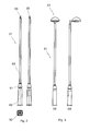
- Figure 4 are views (a) from above, (b) elevation from the side, (c) elevation from the front of a single vertical link arm (25).
- Figure 5 are views (a) from above, (b) elevation from the side, (c) elevation from the front of a double vertical link arm (26).
- Figure 6 are views (a) from above, (b) elevation from the side, (c) elevation from the front of a single vertical link arm (47).
- Figure 7 are views (a) from above, (b) elevation from the side, (c) elevation from the front of a single vertical link arm (48).
- Figures 8, 9 and 10 show a light (27) mounted on a single vertical link arm, including (27) flat glass (28) figure 8, a lens glass (29) figure 9 and a polycarbonate box (30) in figure 10.
- Figures 11, 12 and 13 show three equivalent setups, but with different lights (27) equipped with vertical and inclined arms (23) which join at a hole (24). In figure 11, (27) it is equipped with flat glass (28), in figure 12 (27) it is equipped with lens glass (29) and in figure 13 (27) it is equipped with a polycarbonate box (30).
- One of the preferred setups for this application, and as can be seen in figure 1, a light (27), includes a chassis (10) which is preferably circular, on which a washer rests (12), a support (13) around a circular edge and with a gap in the central area to which a reflector (14) may be connected, closing the upper section of the light (27) using a cupola (15), to the lower section of the chassis (10) of (27) to include, using a suitable method, a flat glass (28), a lens glass (29) or a polycarbonate box (30) in accordance with the light requirements. Some electrical parts (16) are included in the lights (27), in completely conventional manner and not claimable, which allow the light to come on. These are located inside the reflector (14) using the lamp holder (22).
- The column (31), in one of its possible setups, is formed by two bodies. The first cylindrical body (49) is located at the base of (27) on top of a reinforcing plate on the bottom (52) of the slightly square edge. This extends (49) upwards (49) to a second body (50) which is also cylindrical at the top of which is a cylindrical boot (33). See figure 2.
- The chosen configuration of the columns (31) is cylindrical for both bodies (49 - 50), linked to a hoppered support (51), which joins the body (49) with (50). Nevertheless this column (31) may be set up in other configurations as long as the boot (33) is kept on the upper section in order to mount the light (27).
- The possible setups for the lights (27) with this device are shown in figures 2, 3 and 4. These show that the aforementioned light (27) has three different aspects only by changing the glasses and the box (28, 29, 30) respectively on the lower section.
- The lamp (27) itself and with regard to the columns (31) shown in figure 2, may appear as different lighting equipment depending on which light (27) is used.
- If the single vertical arm (25) as shown in figure 4, a double vertical arm (26) as shown in figure 5, a single vertical arm (47) as shown in figure 6 and eight double vertical arm (48) as shown in figure 7 are used, different configurations are achieved.
- In the example shown, these arms are formed by a single vertical arm (25), a vertical section (56) which is preferably cylindrical and a circular horizontal section (55). As the cylindrical section is hollow it includes a cylindrical hole (54) inside which connects the boot (33), which is also cylindrical, to the column (31) as shown in figures 2 and 3.
- Alternatively the light (27) may include a double vertical link arm (26) as shown in detail in figures 5, (a), (b) and (c). These figures show that (26) has a cylindrical vertical section (37) which is touched to the right, to the left and at the same level by horizontal sections (38), which are perpendicular to (37) ending in curved sections (39). This cylindrical vertical section (37) holds a cylindrical boot (33) on the upper section of the columns (27) due to the fact that is has a hole (34) located on the lower end of (37).
- Alternatively the light (27) may include a single vertical arm (47) in order to mount a column (31). The arm (47) has a vertical section of which is preferably cylindrical (40) which extends upwards to another cylindrical section of a smaller diameter (41). A horizontal section (42) extends perpendicularly from the side of the cylinder's horizontal surface (42), see figure 2. This ends in a curved section (53).
- Finally another alternative for the recognised layout of the light (27) may include a double vertical arm (48) which has a first cylindrical, vertical section (43) which extends upwards to a cylindrical section of a smaller diameter than the previous section (44) from which horizontal sections (45) emerged to the right and left. These end in curved sections (46).
- All arms described, i.e. (25), (26), (47) and (48), have an identical curved area (39), (45), (46), and (53) respectively in the form of a plate (17), which is located in the chassis (10) as shown in figure 1 this figure shows (17) due to drilled holes (19 - 21) in the aforementioned plate (17) and in the chassis (10) respectively.
- The multipurpose nature of the device allows other setups, as shown in figures 8, 9 and 10 using some vertical arms which are formed by two vertically inclined arms (23) joined in a hole (24) which includes the boot (33) located in the upper section of the column (31).
- Having sufficiently described the invention using the attached diagrams, it is easy to understand that any modification to the detail of the mention which is judged to be suitable may be made whenever the essential features of the summarised invention in the following claims are not altered.
Claims (8)
- "IMPROVED DEVICE APPLIED TO LIGHTING EQUIPMENT" which use common parts for all of the setups for the system such as lights, link arms, columns and others, characterised by the fact that this device includes:- Columns (31) in different heights- Single vertical link arms (25 - 47)- Double vertical link arms (26 - 48)- Vertical and inclined arms (23)- Lights (27)- Glass and box (28 - 29 - 30), respectivelyin such a way different lighting equipment are configured that using suitable methods.
- "IMPROVED DEVICE APPLIED TO LIGHTING EQUIPMENT" in accordance with the first claim characterised by the fact that the lighting equipment is configured by columns (31) formed by two bodies or sections which are preferably cylindrical with different diameters. The first section (49) is supported on a plate (52) or the base of (49) with a larger diameter than the second (50) which ends in a cylindrical boot (33) on its upper section.
- "IMPROVED DEVICE APPLIED TO LIGHTING EQUIPMENT" in accordance with the third claim characterised by the fact that the single vertical link arms (25) are formed by a vertical section (28) which is preferably cylindrical which extends to a horizontal section (27) perpendicular to (28) the single free end of which holds a circular plate (45). Within the cylindrical section (28) there is a hole (54) to attach the light (27) to the column (31) and to the boot (33) located on the upper end of the aforementioned column (31).
- "IMPROVED DEVICE APPLIED TO LIGHTING EQUIPMENT" in accordance with the third claim characterised by the fact that the single vertical link arms (47) are formed by a cylindrical vertical section (40) which extends upwards to another cylindrical section of a smaller diameter than the previous section which extends horizontally to a horizontal section (42) perpendicular to (41) the single free end of which holds a circular plate (53). Within this cylindrical section (40) there is a hole (54) to attach the light (27) to the column (31) and to the boot (33) located on the upper end of the aforementioned column (31).
- "IMPROVED DEVICE APPLIED TO LIGHTING EQUIPMENT" in accordance with the third claim characterised by the fact that the double vertical arms (26) are formed by a cylindrical vertical section (37) the upper section of which extends to horizontal sections (38) perpendicular to (26) and aligned along the horizontal axis. The single free end of this holds a circular plate (39). Located on the cylindrical section (37) there is a hole (54) to attach the light (27) to the column (31) and to the cylindrical boot (33) located on the upper end of the aforementioned column (31).
- "IMPROVED DEVICE APPLIED TO LIGHTING EQUIPMENT" in accordance with the third claim characterised by the fact that the double vertical arms in an alternative set up (48) are formed by a cylindrical vertical section (43) the upper section of which extends to another cylindrical section of a smaller diameter (44) which in turn extends perpendicularly to horizontal sections perpendicular to (44) aligned along the horizontal axis. At the single free end there is a circular plate (46) with a hole (54) on the free end of the circular plate (46). This attaches the lights (27) to the column (31) and to the cylindrical boot (33) located on the upper end of the aforementioned column (31).
- "IMPROVED DEVICE APPLIED TO LIGHTING EQUIPMENT" in accordance with the third claim characterised by the fact that the vertical and inclined arms (23) join in a cylindrical hole (24) to attach the light (27) to the column (31) and to the cylindrical boot (33) located on the upper end of the aforementioned column (31).
- "IMPROVED DEVICE APPLIED TO LIGHTING EQUIPMENT" in accordance with the first claim characterised by the fact that the light (27) includes a chassis (10) which is preferably circular on which rest a washer (12), a support (13) with a circular edge and with a gap in the central area to which a reflector (14) may be connected, closing the upper section using a cupola (15), while on the lower section of the chassis (10) there is, using a suitable method, a flat glass (28), a lens glass (29) or a polycarbonate box (30).
Applications Claiming Priority (1)
| Application Number | Priority Date | Filing Date | Title |
|---|---|---|---|
| ES200600925A ES2328761B1 (en) | 2006-04-11 | 2006-04-11 | PERFECTED PROVISION APPLIED TO LIGHTING DEVICES. |
Publications (2)
| Publication Number | Publication Date |
|---|---|
| EP1845302A2 true EP1845302A2 (en) | 2007-10-17 |
| EP1845302A3 EP1845302A3 (en) | 2007-12-05 |
Family
ID=38179956
Family Applications (1)
| Application Number | Title | Priority Date | Filing Date |
|---|---|---|---|
| EP06380159A Ceased EP1845302A3 (en) | 2006-04-11 | 2006-06-12 | Support means for a lighting device |
Country Status (2)
| Country | Link |
|---|---|
| EP (1) | EP1845302A3 (en) |
| ES (1) | ES2328761B1 (en) |
Cited By (3)
| Publication number | Priority date | Publication date | Assignee | Title |
|---|---|---|---|---|
| EP2123971A1 (en) | 2008-05-20 | 2009-11-25 | C & G Carandini, S.A. | Improved layout for multiple lighting |
| WO2010116128A1 (en) * | 2009-04-07 | 2010-10-14 | Primalux Limited | Lighting system |
| EP2840297A1 (en) * | 2013-08-19 | 2015-02-25 | Hugo Brennenstuhl GmbH & Co. KG | Illumination device |
Citations (1)
| Publication number | Priority date | Publication date | Assignee | Title |
|---|---|---|---|---|
| ES1058498U (en) | 2004-09-30 | 2004-12-16 | C. & G. CARANDINI, S.A. | Modular system for construction of luminaires |
Family Cites Families (10)
| Publication number | Priority date | Publication date | Assignee | Title |
|---|---|---|---|---|
| US3170634A (en) * | 1961-06-19 | 1965-02-23 | Mc Graw Edison Co | Luminaire |
| US3903409A (en) * | 1974-03-29 | 1975-09-02 | Zephyr Ind Inc | Outdoor light mounting device |
| US5260860A (en) * | 1992-03-23 | 1993-11-09 | Hubbell Incorporated | Expanding tenon clamp |
| ES2119586B1 (en) * | 1994-04-29 | 1999-05-16 | Hergom Ind | MODULAR STRUCTURE SYSTEM FOR STREETLIGHTS AND FLAGS. |
| US5954426A (en) * | 1997-12-04 | 1999-09-21 | Whittington; Anderson H. | Interchangeable lamp |
| WO1999047770A1 (en) * | 1998-03-19 | 1999-09-23 | Fournier Paul W | Utility pole mounting structure |
| WO2000019142A1 (en) * | 1998-09-25 | 2000-04-06 | U.S. Pole Company, Inc. | Interchangeable outdoor luminaire and method of assembly thereof |
| DE19949784A1 (en) * | 1999-10-15 | 2001-04-26 | Siteco Beleuchtungstech Gmbh | Fixing module for lamps to be fitted on lampposts or on masts has base body to fit on lamppost and brackets to fit support arms for lamps fitted to base body by connection elements |
| DE29920109U1 (en) * | 1999-11-16 | 2000-02-17 | Vulkan Werk für Industrie- und Außenbeleuchtung GmbH, 50825 Köln | Modular lighting system |
| GB0408654D0 (en) * | 2004-04-19 | 2004-05-19 | Abacus Holdings Ltd | Luminaires |
-
2006
- 2006-04-11 ES ES200600925A patent/ES2328761B1/en not_active Expired - Fee Related
- 2006-06-12 EP EP06380159A patent/EP1845302A3/en not_active Ceased
Patent Citations (1)
| Publication number | Priority date | Publication date | Assignee | Title |
|---|---|---|---|---|
| ES1058498U (en) | 2004-09-30 | 2004-12-16 | C. & G. CARANDINI, S.A. | Modular system for construction of luminaires |
Cited By (5)
| Publication number | Priority date | Publication date | Assignee | Title |
|---|---|---|---|---|
| EP2123971A1 (en) | 2008-05-20 | 2009-11-25 | C & G Carandini, S.A. | Improved layout for multiple lighting |
| WO2010116128A1 (en) * | 2009-04-07 | 2010-10-14 | Primalux Limited | Lighting system |
| EP2840297A1 (en) * | 2013-08-19 | 2015-02-25 | Hugo Brennenstuhl GmbH & Co. KG | Illumination device |
| CN104421816A (en) * | 2013-08-19 | 2015-03-18 | 雨果·布伦纳斯图尔有限责任两合公司 | Illumination device |
| CN104421816B (en) * | 2013-08-19 | 2019-04-02 | 雨果·布伦纳斯图尔有限责任两合公司 | Lighting device |
Also Published As
| Publication number | Publication date |
|---|---|
| EP1845302A3 (en) | 2007-12-05 |
| ES2328761A1 (en) | 2009-11-17 |
| ES2328761B1 (en) | 2010-07-09 |
Similar Documents
| Publication | Publication Date | Title |
|---|---|---|
| CN102072471A (en) | Street lamp post connecting device | |
| CN104471314B (en) | The illuminator being easily installed with erecting device | |
| CN202167189U (en) | Multidirectional indication guide board | |
| EP1845302A2 (en) | Support means for a lighting device | |
| JP2005158316A (en) | Beam lighting device | |
| CN102514659B (en) | Combination mount for gauges, gauge guards, front turn signals and front spoiler | |
| JP2010218835A (en) | Outdoor luminaire | |
| DE502007001769D1 (en) | Headlights for vehicles and assembly procedures | |
| WO2005035345A1 (en) | Lighting device for vehicles, particularly bicycles | |
| EP1762782A3 (en) | Installation of street furniture equipment on a street lamp | |
| CN105276474A (en) | Street lamp with elastic protective function | |
| CN213089525U (en) | An interior design floor lamp | |
| EP1386832A1 (en) | Multiple stand for bicycles | |
| CN101451681B (en) | Fixation device and fixation method for inserted light guide column | |
| TWM503454U (en) | Lamp post structure device | |
| CN218914730U (en) | Lamp with inner support reinforcing structure lampshade | |
| CN201715402U (en) | Landscape light applicable to residential districts | |
| CN210069674U (en) | A lighting device for town road | |
| CN215636931U (en) | Landscape street lamp capable of planting flowers | |
| CN219318333U (en) | Emergency fire-fighting illuminating lamp with steering assembly | |
| CN113551182A (en) | Detachable wind-resistant street lamp | |
| CN217540572U (en) | Economic and attractive street lamp | |
| JP3252770U (en) | Mounting fixture for lighting fixtures with pan heads | |
| EP0751341B1 (en) | Support arm for outdoor lamp | |
| JP2003213634A (en) | Elevating type marking board with electric display part |
Legal Events
| Date | Code | Title | Description |
|---|---|---|---|
| PUAI | Public reference made under article 153(3) epc to a published international application that has entered the european phase |
Free format text: ORIGINAL CODE: 0009012 |
|
| AK | Designated contracting states |
Kind code of ref document: A2 Designated state(s): AT BE BG CH CY CZ DE DK EE ES FI FR GB GR HU IE IS IT LI LT LU LV MC NL PL PT RO SE SI SK TR |
|
| AX | Request for extension of the european patent |
Extension state: AL BA HR MK YU |
|
| PUAL | Search report despatched |
Free format text: ORIGINAL CODE: 0009013 |
|
| AK | Designated contracting states |
Kind code of ref document: A3 Designated state(s): AT BE BG CH CY CZ DE DK EE ES FI FR GB GR HU IE IS IT LI LT LU LV MC NL PL PT RO SE SI SK TR |
|
| AX | Request for extension of the european patent |
Extension state: AL BA HR MK YU |
|
| 17P | Request for examination filed |
Effective date: 20080104 |
|
| 17Q | First examination report despatched |
Effective date: 20080409 |
|
| AKX | Designation fees paid |
Designated state(s): AT BE BG CH CY CZ DE DK EE ES FI FR GB GR HU IE IS IT LI LT LU LV MC NL PL PT RO SE SI SK TR |
|
| STAA | Information on the status of an ep patent application or granted ep patent |
Free format text: STATUS: THE APPLICATION HAS BEEN REFUSED |
|
| 18R | Application refused |
Effective date: 20090719 |