EP1845313A1 - Appareil à accumulation de chaleur - Google Patents
Appareil à accumulation de chaleur Download PDFInfo
- Publication number
- EP1845313A1 EP1845313A1 EP07006630A EP07006630A EP1845313A1 EP 1845313 A1 EP1845313 A1 EP 1845313A1 EP 07006630 A EP07006630 A EP 07006630A EP 07006630 A EP07006630 A EP 07006630A EP 1845313 A1 EP1845313 A1 EP 1845313A1
- Authority
- EP
- European Patent Office
- Prior art keywords
- heat
- circuit
- temperature range
- temperature
- evaporator
- Prior art date
- Legal status (The legal status is an assumption and is not a legal conclusion. Google has not performed a legal analysis and makes no representation as to the accuracy of the status listed.)
- Withdrawn
Links
- 238000005338 heat storage Methods 0.000 title claims description 27
- XLYOFNOQVPJJNP-UHFFFAOYSA-N water Substances O XLYOFNOQVPJJNP-UHFFFAOYSA-N 0.000 claims description 3
- 241000196324 Embryophyta Species 0.000 claims 4
- 238000009434 installation Methods 0.000 claims 1
- 238000011144 upstream manufacturing Methods 0.000 claims 1
- 230000004087 circulation Effects 0.000 abstract description 6
- 239000012080 ambient air Substances 0.000 description 2
- 239000003673 groundwater Substances 0.000 description 2
- 239000003570 air Substances 0.000 description 1
- 230000007423 decrease Effects 0.000 description 1
- 238000010438 heat treatment Methods 0.000 description 1
- 239000003921 oil Substances 0.000 description 1
Images

Classifications
-
- F—MECHANICAL ENGINEERING; LIGHTING; HEATING; WEAPONS; BLASTING
- F24—HEATING; RANGES; VENTILATING
- F24D—DOMESTIC- OR SPACE-HEATING SYSTEMS, e.g. CENTRAL HEATING SYSTEMS; DOMESTIC HOT-WATER SUPPLY SYSTEMS; ELEMENTS OR COMPONENTS THEREFOR
- F24D11/00—Central heating systems using heat accumulated in storage masses
- F24D11/02—Central heating systems using heat accumulated in storage masses using heat pumps
- F24D11/0214—Central heating systems using heat accumulated in storage masses using heat pumps water heating system
- F24D11/0221—Central heating systems using heat accumulated in storage masses using heat pumps water heating system combined with solar energy
-
- Y—GENERAL TAGGING OF NEW TECHNOLOGICAL DEVELOPMENTS; GENERAL TAGGING OF CROSS-SECTIONAL TECHNOLOGIES SPANNING OVER SEVERAL SECTIONS OF THE IPC; TECHNICAL SUBJECTS COVERED BY FORMER USPC CROSS-REFERENCE ART COLLECTIONS [XRACs] AND DIGESTS
- Y02—TECHNOLOGIES OR APPLICATIONS FOR MITIGATION OR ADAPTATION AGAINST CLIMATE CHANGE
- Y02B—CLIMATE CHANGE MITIGATION TECHNOLOGIES RELATED TO BUILDINGS, e.g. HOUSING, HOUSE APPLIANCES OR RELATED END-USER APPLICATIONS
- Y02B10/00—Integration of renewable energy sources in buildings
- Y02B10/20—Solar thermal
-
- Y—GENERAL TAGGING OF NEW TECHNOLOGICAL DEVELOPMENTS; GENERAL TAGGING OF CROSS-SECTIONAL TECHNOLOGIES SPANNING OVER SEVERAL SECTIONS OF THE IPC; TECHNICAL SUBJECTS COVERED BY FORMER USPC CROSS-REFERENCE ART COLLECTIONS [XRACs] AND DIGESTS
- Y02—TECHNOLOGIES OR APPLICATIONS FOR MITIGATION OR ADAPTATION AGAINST CLIMATE CHANGE
- Y02B—CLIMATE CHANGE MITIGATION TECHNOLOGIES RELATED TO BUILDINGS, e.g. HOUSING, HOUSE APPLIANCES OR RELATED END-USER APPLICATIONS
- Y02B10/00—Integration of renewable energy sources in buildings
- Y02B10/70—Hybrid systems, e.g. uninterruptible or back-up power supplies integrating renewable energies
Definitions
- the invention relates to a heat storage system with a heat storage, a heat pump with evaporator and compressor, a first controllable circuit for a first temperature range, which connects a heat source directly to the heat storage, and a second controllable circuit for a second temperature range, which the heat source with connects to the heat storage via the heat pump.
- Such a heat storage system is through the EP 0 887 602 A1 known.
- the heat source is solar energy, with a solar collector circuit is thermally coupled directly to a load circuit when the heat absorbed sufficient to heat the consumer circuit directly.
- the heat pump is bypassed. If the temperature on the solar collector decreases, then it is switched to a second circuit and thus to a use of solar energy via the heat pump.
- input temperatures up to about 25 ° C are processed.
- the heat pump is switched off when the permissible maximum temperature is reached. Disadvantageously, thus not all the available energy is utilized, but only the energy on the evaporator side up to about 25 ° C is used.
- the object of the invention is thus seen to further develop the heat storage system of the type mentioned in such a way that an efficient energy yield is achieved.
- a switchable mixing line is provided, which is fluidly connectable before the evaporator with the second circuit so that a third controllable circuit for a third temperature range is formed and the different circuits with different heat sources for the three temperature ranges are connectable.
- the heat storage system according to the invention can be easily replaced with a conventional heat pump, since it requires only two connections for the heat source and two connections for the heat storage for operation.
- Another significant advantage of the heat storage system according to the invention is that any heat source such as groundwater, ambient air, a heating system or a solar collector can be easily connected. Using the three circuits with the three different temperature ranges, each heat source can be used efficiently.
- the admixture line can deliver the medium from an external location.
- the admixing line is connected in front of and behind the evaporator with the second circuit.
- the cooled heat transfer medium after the evaporator is partially diverted into the admixing and fed to the coming of the heat source warm heat transfer medium before the evaporator.
- the second temperature range is between 5 ° C and 25 ° C
- the third temperature range between 25 ° C and a temperature which is lower than that of the heat accumulator
- the first temperature range is above the temperature of the heat accumulator.
- the circuit between the individual circuits is advantageously carried out via two-way valves and / or three-way valves and / or four-way valves and the heat transfer medium is water or air or oil or a similar comparable medium used.
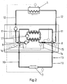
- the heat storage system has a heat storage 1, a heat pump 2 with an evaporator 3, a compressor 4 and an expansion valve 5.
- 1 shows, on the basis of the strongly emphasized lines, a first circuit 6 for a first temperature range, which is connected to a heat source 7.
- valves 8, 9 are provided which can connect the heat source line 10 with the heat pump line 11 or the heat storage line 12.
- the valves 8, 9 are connected in the circuit 6 so that a direct connection between the heat source 7 and the heat accumulator 1 is formed.
- the heat source line 10 and the heat storage line 12 form the circuit 6.
- the heat pump 2 is thus turned off.
- This circuit 6 is used in a solar collector as the heat source 7, wherein the temperature of the coming of the heat source 7 heat transfer medium is higher than the temperature of the heat accumulator. 1
- Fig. 2 here are the valves 8, 9 connected so that the heat pump 2 is switched with its heat pump line 11 and no direct connection between the heat source 7 and the heat storage 1 is.
- the heat source line 10 the heat pump line 11 and the heat storage line 12 connected in series.
- This circuit corresponds to a second circuit 13 for a second temperature range, in which the heat source 7 has a temperature between 5 ° C and 25 ° C. Ambient air, water from lakes, rivers or groundwater, or geothermal heat are suitable as the heat source 7 in this temperature range.
- the heated medium passes from the heat source 7 directly into the evaporator 3.
- An admixing line 14, which is connected in parallel to the evaporator 3, is blocked by a valve 15 arranged in front of the evaporator 3.
- Cold heat transfer medium which is located in the admixing line 14, is not mixed with the coming of the heat source 7 warm heat transfer medium in this cycle.
- the circulation of the medium from the heat source 7 is conveyed by a pump 16.
- the brought by the heat pump 2 to a higher heat level medium is conveyed to the compressor 4 by means of a pump 17 to the heat storage 1.
- the heat is released via a heat exchanger to the heat storage 1.
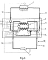
- the heat source has a temperature between 25 ° C and a temperature which is lower than the temperature of the heat accumulator 1.
- the heat pump would now be turned off to destroy to prevent the heat pump.
- the heat storage system according to the invention is now mixed via the admixing line 14 with open valve 15 as long as the medium coming from the heat source 7 with the warm heat transfer medium, until at the inlet side of the evaporator 3, a mixed medium having a maximum temperature of about 25 ° C is formed.
- the entire amount of heat from the heat source 7 can also be used with a temperature higher than 25 ° C.
- the heat source pipe 10 In the third circuit 18, the heat source pipe 10, the Heat pump line 11 and the heat storage line 12 connected in series and the admixing line 14 is connected in parallel to the heat pump line 11 in front of and behind the evaporator 3. All three circuits 6, 13, 18 and the circuit of the respective valves 8, 9 are controlled by a controller 19.
- the heat storage system according to the invention thus utilizes the entire energy range provided by the various heat sources, so that an efficient energy yield is achieved.
- the system according to the invention can be easily replaced by a conventional heat pump, with only the heat source 1 and the heat storage 7 must be reconnected.
Landscapes
- Engineering & Computer Science (AREA)
- Life Sciences & Earth Sciences (AREA)
- Sustainable Development (AREA)
- Sustainable Energy (AREA)
- Physics & Mathematics (AREA)
- Thermal Sciences (AREA)
- Chemical & Material Sciences (AREA)
- Combustion & Propulsion (AREA)
- Mechanical Engineering (AREA)
- General Engineering & Computer Science (AREA)
- Central Heating Systems (AREA)
Applications Claiming Priority (1)
| Application Number | Priority Date | Filing Date | Title |
|---|---|---|---|
| DE102006017198A DE102006017198A1 (de) | 2006-04-12 | 2006-04-12 | Wärmespeicheranlage |
Publications (1)
| Publication Number | Publication Date |
|---|---|
| EP1845313A1 true EP1845313A1 (fr) | 2007-10-17 |
Family
ID=38179959
Family Applications (1)
| Application Number | Title | Priority Date | Filing Date |
|---|---|---|---|
| EP07006630A Withdrawn EP1845313A1 (fr) | 2006-04-12 | 2007-03-30 | Appareil à accumulation de chaleur |
Country Status (2)
| Country | Link |
|---|---|
| EP (1) | EP1845313A1 (fr) |
| DE (1) | DE102006017198A1 (fr) |
Cited By (3)
| Publication number | Priority date | Publication date | Assignee | Title |
|---|---|---|---|---|
| FR2927152A1 (fr) * | 2008-02-04 | 2009-08-07 | Airpac Sarl | Dispositif de transfert de chaleur comprenant une enceinte pre-equipee. |
| EP2543935A4 (fr) * | 2010-03-05 | 2013-11-20 | Mitsubishi Heavy Ind Ltd | Pompe à chaleur pour eau chaude et son procédé de commande |
| KR20260014158A (ko) | 2024-07-23 | 2026-01-30 | 조재훈 | 중공형을 절단해 부력체를 공급하고 융착성형한 부표와 그 제조장치 및 그 제조방법 |
Citations (4)
| Publication number | Priority date | Publication date | Assignee | Title |
|---|---|---|---|---|
| DE2619744A1 (de) * | 1976-05-05 | 1977-11-24 | Bosch Gmbh Robert | Verfahren zum betreiben einer heizungsanlage und heizungsvorrichtung hierfuer |
| FR2366521A1 (fr) * | 1976-10-04 | 1978-04-28 | Cerca | Installation de chauffage et/ou de refroidissement |
| DE2936656A1 (de) * | 1979-09-11 | 1981-03-26 | Robert Bosch Gmbh, 70469 Stuttgart | Heizungsanlage mit einer waermepumpe |
| EP0887602A1 (fr) * | 1997-06-28 | 1998-12-30 | VIESSMANN WERKE GmbH & CO. | Pompe à chaleur |
Family Cites Families (1)
| Publication number | Priority date | Publication date | Assignee | Title |
|---|---|---|---|---|
| DE3027085A1 (de) * | 1980-07-17 | 1982-02-11 | Adolf H. 7322 Donzdorf Borst | Anlage zur gewinnung von biogas |
-
2006
- 2006-04-12 DE DE102006017198A patent/DE102006017198A1/de not_active Ceased
-
2007
- 2007-03-30 EP EP07006630A patent/EP1845313A1/fr not_active Withdrawn
Patent Citations (4)
| Publication number | Priority date | Publication date | Assignee | Title |
|---|---|---|---|---|
| DE2619744A1 (de) * | 1976-05-05 | 1977-11-24 | Bosch Gmbh Robert | Verfahren zum betreiben einer heizungsanlage und heizungsvorrichtung hierfuer |
| FR2366521A1 (fr) * | 1976-10-04 | 1978-04-28 | Cerca | Installation de chauffage et/ou de refroidissement |
| DE2936656A1 (de) * | 1979-09-11 | 1981-03-26 | Robert Bosch Gmbh, 70469 Stuttgart | Heizungsanlage mit einer waermepumpe |
| EP0887602A1 (fr) * | 1997-06-28 | 1998-12-30 | VIESSMANN WERKE GmbH & CO. | Pompe à chaleur |
Cited By (4)
| Publication number | Priority date | Publication date | Assignee | Title |
|---|---|---|---|---|
| FR2927152A1 (fr) * | 2008-02-04 | 2009-08-07 | Airpac Sarl | Dispositif de transfert de chaleur comprenant une enceinte pre-equipee. |
| EP2543935A4 (fr) * | 2010-03-05 | 2013-11-20 | Mitsubishi Heavy Ind Ltd | Pompe à chaleur pour eau chaude et son procédé de commande |
| US9664415B2 (en) | 2010-03-05 | 2017-05-30 | Mitsubishi Heavy Industries, Ltd. | Hot-water heat pump and method of controlling the same |
| KR20260014158A (ko) | 2024-07-23 | 2026-01-30 | 조재훈 | 중공형을 절단해 부력체를 공급하고 융착성형한 부표와 그 제조장치 및 그 제조방법 |
Also Published As
| Publication number | Publication date |
|---|---|
| DE102006017198A1 (de) | 2007-10-25 |
Similar Documents
| Publication | Publication Date | Title |
|---|---|---|
| DE102012208174B4 (de) | Wärmepumpe und verfahren zum pumpen von wärme im freikühlungsmodus | |
| DE1604205A1 (de) | Klimaanlage | |
| DE102009004501B4 (de) | Wärmepumpe und Verfahren zur Regelung der Quelleneingangstemperatur an der Wärmepumpe | |
| EP2354677B1 (fr) | Utilisation de la chaleur du reflux de chauffage urbain | |
| DE102008038617A1 (de) | Verfahren und Vorrichtung zur Wärmenutzung | |
| DE2747813B2 (de) | Anlage zur Raumheizung und Brauchwasserbereitung | |
| EP3136005A1 (fr) | Installation de chauffage et son procede de fonctionnement | |
| EP2287547B1 (fr) | Pompe à chaleur et procédé de réglage de la température d'entrée de sources sur une pompe à chaleur | |
| EP2458304A2 (fr) | Installation de pompe à chaleur comprenant une pompe à chaleur et procédé de fonctionnement d'une telle installation de pompe à chaleur | |
| DE102008057495A1 (de) | Wärmespeicheranordnung | |
| DE102015207079A1 (de) | Heizsystem | |
| DE102006017198A1 (de) | Wärmespeicheranlage | |
| DE102015118826A1 (de) | Anordnung und Verfahren zur Bereitstellung von warmem Trinkwasser mit einem Wärmeübertrager | |
| DE102006023627B4 (de) | Solaranlage | |
| DE102014000671A1 (de) | Solaranlage und Verfahren zum Betreiben einer solchen | |
| DE102007062342B4 (de) | Verfahren und Anordnung zur Erhöhung des Temperaturniveaus im Kreislauf solarthermischer Anlagen oder Blockheizkraftwerke | |
| DE102009038738A1 (de) | Heizungsanlage | |
| DE102008020637A1 (de) | Warmwasserversorgungsanlage mit einem Warmwasserspeicher | |
| DE202016103592U1 (de) | System umfassend zumindest einen Wärmespeicher | |
| DE10102022A1 (de) | Wasserheizanlage | |
| DE19628708B4 (de) | Wasserheizanlage | |
| DE3215582A1 (de) | Heizungsanlage sowie hierfuer geeigneter heizkoerper | |
| EP3460340B1 (fr) | Procédé de fourniture de chaleur, installation de récupération de chaleur et unité de fourniture de chaleur | |
| DE202008000374U1 (de) | Wärmepumpe | |
| EP0330648B1 (fr) | Installation de chauffage avec un appareil de chauffage pour un agent caloporteur au moins |
Legal Events
| Date | Code | Title | Description |
|---|---|---|---|
| PUAI | Public reference made under article 153(3) epc to a published international application that has entered the european phase |
Free format text: ORIGINAL CODE: 0009012 |
|
| AK | Designated contracting states |
Kind code of ref document: A1 Designated state(s): AT BE BG CH CY CZ DE DK EE ES FI FR GB GR HU IE IS IT LI LT LU LV MC MT NL PL PT RO SE SI SK TR |
|
| AX | Request for extension of the european patent |
Extension state: AL BA HR MK YU |
|
| AKX | Designation fees paid | ||
| STAA | Information on the status of an ep patent application or granted ep patent |
Free format text: STATUS: THE APPLICATION IS DEEMED TO BE WITHDRAWN |
|
| 18D | Application deemed to be withdrawn |
Effective date: 20080418 |
|
| REG | Reference to a national code |
Ref country code: DE Ref legal event code: 8566 |