EP1845501A2 - Système de mesure doté d'au moins un conducteur de détection - Google Patents
Système de mesure doté d'au moins un conducteur de détection Download PDFInfo
- Publication number
- EP1845501A2 EP1845501A2 EP07001439A EP07001439A EP1845501A2 EP 1845501 A2 EP1845501 A2 EP 1845501A2 EP 07001439 A EP07001439 A EP 07001439A EP 07001439 A EP07001439 A EP 07001439A EP 1845501 A2 EP1845501 A2 EP 1845501A2
- Authority
- EP
- European Patent Office
- Prior art keywords
- measuring system
- unit
- signal
- line
- switching
- Prior art date
- Legal status (The legal status is an assumption and is not a legal conclusion. Google has not performed a legal analysis and makes no representation as to the accuracy of the status listed.)
- Granted
Links
Images

Classifications
-
- G—PHYSICS
- G08—SIGNALLING
- G08C—TRANSMISSION SYSTEMS FOR MEASURED VALUES, CONTROL OR SIMILAR SIGNALS
- G08C19/00—Electric signal transmission systems
-
- G—PHYSICS
- G01—MEASURING; TESTING
- G01D—MEASURING NOT SPECIALLY ADAPTED FOR A SPECIFIC VARIABLE; ARRANGEMENTS FOR MEASURING TWO OR MORE VARIABLES NOT COVERED IN A SINGLE OTHER SUBCLASS; TARIFF METERING APPARATUS; MEASURING OR TESTING NOT OTHERWISE PROVIDED FOR
- G01D3/00—Indicating or recording apparatus with provision for the special purposes referred to in the subgroups
- G01D3/02—Indicating or recording apparatus with provision for the special purposes referred to in the subgroups with provision for altering or correcting the law of variation
- G01D3/022—Indicating or recording apparatus with provision for the special purposes referred to in the subgroups with provision for altering or correcting the law of variation having an ideal characteristic, map or correction data stored in a digital memory
-
- G—PHYSICS
- G01—MEASURING; TESTING
- G01D—MEASURING NOT SPECIALLY ADAPTED FOR A SPECIFIC VARIABLE; ARRANGEMENTS FOR MEASURING TWO OR MORE VARIABLES NOT COVERED IN A SINGLE OTHER SUBCLASS; TARIFF METERING APPARATUS; MEASURING OR TESTING NOT OTHERWISE PROVIDED FOR
- G01D3/00—Indicating or recording apparatus with provision for the special purposes referred to in the subgroups
- G01D3/08—Indicating or recording apparatus with provision for the special purposes referred to in the subgroups with provision for safeguarding the apparatus, e.g. against abnormal operation, against breakdown
Definitions
- the invention relates to a measuring system for detecting at least one measuring signal according to the preamble of claim 1.
- Such a measuring system has at least one sensor line, which detects a state of the measuring system, for example a voltage value at a nodal point of a circuit board or the supply voltage on a supply line, and transmits it in the form of a sensor signal to a control unit connectable to the measuring system.
- the sensor signal transmitted in this way can then be evaluated in the control unit and used to readjust the measuring system, for example a supply voltage provided for supply to the measuring system.
- a sense line in this sense is thus understood to mean a sensor line which is arranged on a component of the measuring system and cooperates with the component in such a way that it samples a state of the measuring system or the component of the measuring system and returns it to the control device in the form of a sensor signal and thus a signal Control of the measuring system allows.
- the sensor lines provided for this purpose are here as separate lines, among others, For connection of the measuring system with the control device lines used, for example, measuring signal lines for the transmission of a measured variable of the measuring system representing measuring signals or supply lines for providing a supply voltage, and thus constitute an additional connection between the measuring system and the control unit.
- An embodiment of such a generic measuring system can in particular have a measuring unit for detecting a measuring signal and a configuration unit for configuring and calibrating the measuring system.
- the measuring system can then be connected to the control unit, which can have an evaluation unit for evaluating the measuring signals received by the measuring system, a supply unit for providing a supply voltage and a calibration unit for calibrating the measuring system.
- the evaluation unit, the supply unit and the calibration unit of the control unit are in each case connected via measuring signal lines, supply lines and calibration lines to the measuring system.
- the measuring system Before commissioning the measuring system, the measuring system is connected via the calibration lines to the calibration unit of the control unit and calibrated and configured by means of the calibration and configuration data transmitted by the calibration unit of the control unit. During operation, the measuring system acquires a measured variable in the form of measured data via the measuring unit and transmits it in the form of measuring signals via the measuring signal lines to the evaluation unit of the control unit, in which the measuring signals are processed and evaluated. If recalibration is required during operation, the measuring operation is interrupted and the measuring system is in turn connected to the calibration unit of the control unit via the calibration lines and recalibrated.
- Such a measuring system in the form of an angle sensor is from the DE 196 52 988 C2 known that for detecting the relative positions of two Motor vehicle parts, z.
- a chassis and a chassis position-dependent electrical control signals generated by a magnet and a cooperating with the Hall Hall sensor, the magnet and the Hall sensor are arranged rotatable relative to each other and the Hall sensor provides a dependent of the relative angle of rotation of the two parts electrical voltage signal.
- the measuring system embodied as an angle sensor comprises an electronic correction unit forming a configuration unit, which can be connected to a control unit via an interface, in particular a serial bus in the form of an I 2 C bus.
- the control unit supplies correction angle-dependent correction values to the correction unit in a calibration phase, which are stored in a memory and used for configuration and calibration of the measurement system.
- the serial bus in this case represents an interface of the measuring system, via which the control unit for calibration and configuration of the measuring system can be connected to the measuring system and which must be provided in parallel with the measuring signal lines and supply lines serving for the transmission of measuring signals and the supply voltage.
- a disadvantage of such measuring systems is thus that for connecting the measuring system with the signals of the measuring system processing and the measuring system controlling control unit a plurality of parallel connecting lines must be provided, which make the connection of the measuring system to the control unit and make consuming.
- a measuring system in which lines for connecting the measuring system to a control unit are saved by measuring signals are transmitted via supply lines is from the EP 0 866 391 A1 which provides a measuring system designed as a position-measuring device, which is used to determine the position of two parts which are movable relative to one another, for example on a machine tool.
- the supply lines transmit a supply voltage in the form of a DC voltage signal for powering the measuring system and the other time-modulated, modulated measurement signals that are modulated onto the supply voltage, transmitted to the control unit and evaluated in modulator / demodulator units of the control unit.
- a switching unit which switches the at least one sensor line of the measuring system such that it depends on the switching state of the switching unit as a sensing line for transmitting the sensor signal or as a data line for transmitting a different signal from the sensor signal signal is used.
- the invention is based on the basic idea that sensor lines, which are provided in a measuring system in order to sense a state of the measuring system as a sensing line and transmit them in the form of sensor signals to a control unit connected to the sensor line, are designed to be switchable by means of a switching unit On the other hand, they can also be switched over and connected to components of the measuring system in such a way that they serve as a data line for the transmission of data signals that are different from the sensor signals.
- the invention thus enables a multiple use of one or more sensor lines of the measuring system, on the one hand in a conventional manner as sense lines and on the other as data lines for the transmission of further Data signals.
- the invention utilizes the knowledge that sensor lines used as sense lines do not necessarily have to be constantly provided, but can be switched such that they are used at specific times, for example at specific intervals or in certain states of the measuring system (for example in normal operation) Sensing lines and in other times (for example, in a calibration phase) are used as data lines.
- An essential advantage of the invention is that lines can be saved by using one or more sensor lines of the measuring system several times. This is achieved by arranging a switching unit in each sensor line in the measuring system, by means of which the sensor line can then be switched and connected to components of the measuring system.
- the required structural change of the measuring system, consisting in the arrangement of the switching unit on the sensor line, is thus low and does not affect the normal operation and functionality of the measuring system.
- the switching unit preferably connects the sensor line of the measuring system to a supply line such that the sensor line scans the supply voltage transmitted via the supply line and transmits it as a sense line to a control unit connected to the measuring system.
- the sensor line can then be connected to the supply line and scans the supply voltage.
- the sensor signal transmitted by the sensor line represents a supply voltage signal which is transmitted to the control unit and can be evaluated accordingly by the control unit.
- control unit that can be connected to the measuring system here has a supply unit which evaluates the supply voltage signal transmitted by the sensor line and utilizes it to readjust the supply voltage. In this way, fluctuations in the supply voltage and external influences, such as temperature influences, can be readjusted.
- one or more sensor lines of the measuring system can be switched by means of a respective switching unit such that they serve as a sensor line, for example for transmitting a supply voltage signal, and as a data line for transmitting a data signal.
- the switching unit switches the sensor line in this case so that it connects the sensor line for transmitting the data signal with a measuring unit of the measuring system and / or a configuration unit of the measuring system.
- the sensor line is thus connected to the measuring unit or the configuration unit so that it can be used to transmit data signals, in particular the transmission of measurement signals from the measuring unit to the control unit or bus signals between the control unit and the configuration unit.
- the sensor line is thus used multiple times in this case and, depending on the switching state of the switching unit, transmits either a sensor signal as sensing line or a data signal of the measuring unit or the configuration unit as data line.
- the measuring system is in this case designed so that the sensor line is connected depending on the switching state of the switching unit either with a supply line and a sensor signal in the form of a supply voltage signal for scanning the supply line transmits, by means of which the supply voltage can then be readjusted, or with the measuring unit and or is connected to the configuration unit and transmits a data signal which is formed by the measurement signals received by the measurement unit or by bus signals exchanged between the configuration unit and the control unit.
- the sensor line is switchable during operation of the measuring system and can thus be used at certain times, for example at certain time intervals, as a sense line and in other times as a data line for the transmission of data signals.
- the sensor line preferably represents a serial bus and thus forms a serial interface between the configuration unit of the measuring system and the control unit connectable to the measuring system, in particular a calibration unit of the control unit. If the sensor line is thus connected to the configuration unit of the measuring system, it serves as a serial bus, via which configuration and calibration data in the form of bus signals can be exchanged between the control unit and the measuring system.
- the trained as a serial bus sensor line is in this way a universal interface between the measuring system and the control unit over which can be done in the context of configuration and calibration adjustment of the measuring system and at the same time a connection for tests, condition measurements and status queries and the like provides.
- the transmitted bus signals may be calibration data for calibration of the measuring system, which are transmitted from the calibration unit of the control unit to the configuration unit of the measuring system and stored in the configuration unit, but also device-specific information, for example specified by the manufacturer , the measuring system identifying information sent from the configuration unit to the calibration unit and evaluated by the control unit.
- the serial bus is embodied here as an I 2 C bus and thus provides a standardized interface between the measuring system and the control unit.
- the serial bus it is also conceivable to design the serial bus as a so-called 1-wire bus, which only needs one line for the transmission of data signals. In the latter case, it is therefore sufficient in principle, only one sensor line switch over and use to transmit data signals as a serial bus.
- the sensor line is then connected by means of the switching unit for calibrating the measuring system, in particular in an initial calibration phase, with the configuration unit of the measuring system, switched after calibration and connected to the supply line, so that the sensor line in the normal operation of Measuring system transmits a supply voltage signal to the control unit, by means of which the supply voltage can be readjusted. If subsequent recalibration of the measuring system is required, the sensor line can in turn be switched over and connected to the configuration unit for transmitting calibration and correction data to the measuring system.
- the switching unit switches the sensor line.
- the switching unit is preferably switched by means of a switching signal, which is transmitted to the switching unit and switches over the switching unit.
- the switching signal can be transmitted to the switching unit via a separate line connected to the switching unit, wherein the additional line can also be connected to the control unit as a control line of the switching unit.
- the switching signal is then made available by the control unit and switches the switching unit so that it is connected either as a sense line, for example with a supply line or as a data line to the measuring unit or the configuration unit of the measuring system.
- the switching signal is formed by a programming voltage signal which is available as standard on the control unit and is used for programming memory components contained in the configuration unit of the measuring system, in particular EPROM or EEPROM memories.
- the switching signal in the form of the programming voltage signal can then via a with the configuration unit and the switching unit associated programming voltage line are transmitted from the control unit to the measuring system, so that no additional line must be provided, but the existing programming voltage line is used both for the programming of the memory devices contained in the configuration unit and for switching the switching unit.
- the switching unit is then switched by the programming voltage signal such that the sensor line is connected to the supply unit when the programming voltage signal is applied to the configuration unit and when the programming voltage signal is not present.
- the sensor line is connected to the supply line by default and serves as a sense line.
- the switching unit switches over the sensor line and connects it to the configuration unit so that bus signals can be transmitted between the configuration unit and the calibration unit.
- the switching signal can also be transmitted via the sensor line itself or a supply line or another line serving for connecting the control device and the measuring system. In this way, no additional line for transmitting the sensor signal and in particular no programming voltage line is required. If the switching signal is transmitted, for example, via a supply line, the supply line is used firstly to transmit the supply voltage to supply the measuring system and secondly to transmit the switching signal for switching the switching unit, so that additional lines for transmitting the switching signal can be saved.
- the switching signal can be modulated onto the signal to be transmitted.
- the switching signal can also be aufmoduliert on the transmitted via a supply line supply voltage, wherein the supply voltage, for example, a DC voltage signal and the switching signal may be a modulated, time-varying and writable by a certain frequency range signal.
- the supply voltage for example, a DC voltage signal
- the switching signal may be a modulated, time-varying and writable by a certain frequency range signal.
- the transmission of a switching signal via a supply line is for example also from the EP 0 866 305 B1 in which a switching signal is transmitted via a supply line serving to supply a position-measuring device and is modulated onto the supply voltage to be transmitted.
- the switching unit can in this case be connected to a switching signal converter, which in turn is connected to the sensor line or the supply line via which the switching signal is transmitted, picks up the switching signal transmitted via the sensor line or the supply line and evaluates it for switching the switching unit.
- the switching signal converter may in particular be a modulator / demodulator unit which demodulates the switching signal modulated onto the supply voltage and makes it available to the switching unit and thus switches the switching unit.
- the switching unit can be designed as an analog switch, as a mechanical switch or as an electronic switch, in particular MOSFET switch.
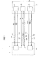
- the measuring system 1 shows a measuring system 1 known from the prior art, which is connected to a control device 2 via measuring signal lines 111, 112, 113, supply lines 121, 122, a serial bus 131, 132 and a programming voltage line 133.
- the measuring system 1 in this case has a measuring unit 11 for detecting a measured variable, which is converted into measuring signals SIN, COS, REF and transmitted in the form of the measuring signals SIN, COS, REF via the measuring signal lines 111, 112, 113 to an evaluation unit 21 of the control unit 2 , Furthermore, in the measuring system 1, a configuration unit 13 is arranged, which serves for the configuration and calibration of the measuring system 1 and is connected via the serial bus 131, 132 and the programming voltage line 133 to a calibration unit 23 of the control unit 2.
- the measuring system 1 can be designed, for example, as a position measuring device for detecting a measured variable in the form of the position of an object, in which the measuring unit 11 supplies position-dependent measuring signals and transmits them via the measuring signal lines 111, 112, 113 to the evaluation unit 21 of the control unit 2.
- the measuring unit 11 in a possible embodiment for incremental position measurement be designed in which a periodic scale division is sampled and generates an analog measurement signal SIN, COS, REF in the form of a sampling signal and transmitted to the control unit 2. It is conceivable, for example, that the measuring unit 11 has one or more Hall sensors which detect the relative movement of a scale provided with magnets and generate corresponding measuring signals SIN, COS, REF indicating the position of the scale.
- the measurement signals SIN, COS, REF can then be transmitted to the control unit either as analog or as digital measurement signals, in the latter case digitalizing the measurement signals SIN, COS, REF already in the measurement system and digital measurement signals SIN, COS, REF via the measurement signal lines 111, 112, 113 are transmitted to the control unit 2 and processed in the control unit 2.
- the invention presented here relates to any type of measuring system for detecting a measured variable and can not be used only for position-measuring devices.
- the measuring system 1 has a configuration unit 13, which is connected to the calibration unit 23 of the control unit 2 via the serial bus 131, 132 and a programming voltage line 133.
- the configuration unit 13 the measuring system 1 can be configured and calibrated prior to commissioning.
- the calibration unit 23 is connected via the serial bus 131, 132 to the configuration unit 13 of the measuring system 1, so that bus signals CLOCK, DATA between the configuration unit 13 of the measuring system 1 and the calibration unit 23 of the control unit 2 can be transmitted.
- the serial bus 131, 132 may in particular be formed as an I 2 C bus comprising two lines 131, 132, which represents a serial digital interface between the calibration unit 23 and the configuration unit 13, and a serial transmission of the bus signals CLOCK, DATA both from the calibration unit 23 to the configuration unit 13 as well as the configuration unit 13 to the calibration unit 23 allows.
- the I 2 C bus uses by default two bidirectional lines 131, 132, via which on the one hand a clock signal CLOCK and on the other hand a data signal DATA is transmitted.
- the I 2 C bus thus represents a standardized interface between the control unit 2 and the measuring system 1 and allows the transmission of serial bus signals via two lines in the form of the serial bus 131, 132.
- the serial bus as a so-called 1-wire bus, which only requires a line for transmitting the serial bus signals, so that one of the lines 131, 132 can be saved.
- the configuration unit 13 of the measuring system 1 conventionally has programmable memory components in the form of, for example, an EPROM or an EEPROM, which store the bus signals CLOCK, DATA received by the calibration unit 23 and provide them for calibration and configuration of the measuring system 1.
- the configuration unit 13 is connected for this purpose to a programming voltage line 133, via which a programming voltage signal VPROG is sent from the calibration unit 23 of the control unit 2 to the configuration unit 13, in particular the memory components contained in the configuration unit 13 and by means of which the programmable memory components can be programmed.
- the measuring system 1 is connected to a supply unit 22 of the control unit 2 via supply lines 121, 122, via which a supply voltage Vp, Vn is provided on the measuring system 1.
- the supply lines 121, 122 are internally connected in the measuring system 1 with the components of the measuring system 1, in particular the measuring unit 11 and the configuration unit 13 of the measuring system 1 and serve for the electrical supply of the measuring system 1 and its components 11, 13.
- temperature changes or the like, or by the line length of the supply lines 121, 122 may cause interference and fluctuations in the supply voltage Vp, Vn on the measuring system 1, so that the supply voltage Vp, Vn on the measuring system 1 deviate from the desired value can.
- the supply voltage Vp, Vn which is available on the measuring system 1, constantly checked and readjusted if necessary.
- two sensor lines 123, 124 are provided on the measuring system 1, which are connected in the measuring system 1 to the supply lines 121, 122 and scan the supply voltage Vp, Vn to the supply lines 121, 122 in the measuring system 1.
- a supply voltage signal Sp, Sn is then transmitted from the measuring system 1 to the supply unit 22 of the control unit 1, evaluated in the supply unit 22 by means of the electronics contained therein and used for readjusting the supply voltage Vp, Vn.
- the sensor lines 123, 124 thus constitute a feedback via which the true supply voltage Vp, Vn available at the measuring system 1 can be detected and an automatic readjustment of the supply voltage Vp, Vn is made possible.
- further sensor lines can also be connected to further measuring points of the measuring system 1 and transmit sensor signals, for example from nodes of a printed circuit board used, from test signals generated internally in the measuring system 1 and / or from reference voltage nodes to the control unit 2.
- a separate line 111, 112, 113; 121, 122, 123, 124, 131, 132, 133 are provided.
- parallel sensor lines 123, 124 and measuring signal lines 111, 112, 113 and the lines of the serial bus 131, 132 are provided and connect the control unit 2 in parallel with the measuring system 1.
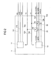
- FIGS. 2 and 3 show two embodiments of a measuring system 1 according to the invention, in which the sensor lines 123, 124 are used several times, by means of switching units 31, 32 arranged in the measuring system 1, either with the supply lines 121, 122 or, depending on From the switching state of the switching units 31, 32, with the configuration unit 13 of the measuring system 1 are connectable.
- Switching units 31, 32 are the sensor lines 123, 124 thus switchable and depending on the switching state of the switching units 31, 32 as sense lines for transmitting sensor signals, namely of the supply lines 121, 122 sampled supply voltage signals, or as data lines for transmitting data signals, namely the bus signals CLOCK, DATA, can be used.
- the sensor lines 123, 124 can in each case be connected either to the supply lines 121, 122 or to the configuration unit 13. If the sensor lines 123, 124 are connected to the configuration unit 13, they function as lines of a serial bus, thus representing a serial interface between the control unit 2 and the measuring system 1 and transmitting bus signals CLOCK, DATA between the calibration unit 23 of the control unit 2 and the Configuration unit 13 of the measuring system 1.
- the sensor lines 123, 124 can also be connected to the measuring signal lines 111, 112, 113 via the switching units 31, 32, so that the sensor lines 123, 124 act as supply lines for supply voltage signals Sp, Sn or as data lines for bus signals CLOCK, DATA or measurement signals SIN, COS to or from the control unit 2.
- the sensor lines 123, 124 act as supply lines for supply voltage signals Sp, Sn or as data lines for bus signals CLOCK, DATA or measurement signals SIN, COS to or from the control unit 2.
- the sensor lines 123, 124 are designed so switchable that they either sensor signals in the form of the supply voltage signals Sp, Sn or., Depending on the switching state of the switching units 31, 32 Data signals in the form of the measurement signals SIN, COS transmitted, the sensor lines 123, 124 are thus connected either to the supply lines 121, 122 or the measuring unit 11.
- the serial bus is designed as a so-called 1-wire bus, which only requires one line for the transmission of the serial bus signals, then in principle it is necessary to use only one of the sensor lines 123, 124 as a serial bus and to switch over accordingly.
- the other sensor line 123, 124 can then be used for example as a measurement signal line 111, 112, 113 for the transmission of measurement signals SIN, COS.
- the sensor lines 123, 124 are switchable so that they can transmit a sensor signal either as sense lines or as data lines in the form of a measurement signal or a bus signal as data lines.
- the sensor lines 123, 124 are thus reusable, so that parallel lines for connecting the measuring system 1 to the control unit 2 can be at least partially saved.
- the switching units 31, 32 are switched so that they first connect the sensor lines to the configuration unit 13 of the measuring system 1 in a calibration phase before commissioning of the measuring system 1, to bus signals CLOCK, DATA from the calibration unit 23 of the control unit 2 for configuration and calibration of the measuring system 1 to the configuration unit 13 of the measuring system. After completion of the calibration phase, the switching units 31, 32 are then switched over and the sensor lines 123, 124 are connected to the supply lines 121, 122.
- the sensor lines 123, 124 scan the supply voltage Vp, Vn at the supply lines 121, 122 on the measuring system 1 and transmit a corresponding supply voltage signal Sp, Sn to the control unit 2, in particular the supply unit 22, by means of the supply voltage Vp, Vn readjusted and thus a constant supply voltage Vp, Vn can be provided independently of external influences on the measuring system 1. If a recalibration during operation of the measuring system 1 is required, the sensor lines 123, 124 can then be switched over at any time by means of the switching units 31, 32 and are connected to the configuration unit 13 in order to transmit bus signals CLOCK, DATA in the form of correction values to the configuration unit 13 of the measurement system 1. If the recalibration is completed, the sensor lines 123, 124 are switched over again, transmit sensor signals in the form of supply voltage signals Sp, Sn and allow the readjustment of the supply voltage Vp, Vn.
- the sensor lines 123, 124 connectable to the supply lines 121, 122 to serve as sense lines, and both the configuration unit 13 and the measuring unit 11 to serve as data lines the sensor lines 123, 124 can be connected to the configuration unit 13 before commissioning to calibrate the measuring system 1, in order then to operate between the supply lines 121, 122 for readjusting the supply voltage Vp, Vn and the measuring unit 11 for transmitting measurement signals SIN, COS to be switched back and forth.
- the switching units 31, 32 are switched by means of switching signals VPROG, VSWITCH, and thus used as sense lines for transmitting sensor signals Sp, Sn or as data lines for the transmission of data signals CLOCK, DATA.
- the switching signals VPROG, VSWITCH are generated by the control unit 2 and transmitted to the switching units 31, 32 of the measuring system 1. 2 and 3 show two principal possibilities of transmitting the switching signals VPROG, VSWITCH to the switching units 31, 32 of the measuring system.
- the switching signal is formed by a programming voltage signal VPROG, which is transmitted via a programming voltage line 133 from the control unit 2 to the measuring system 1. It is advantageous here that the programming voltage signal VPROG is generally available on the measuring system 1 via the programming voltage line 133.
- the programming voltage signal VPROG is conventionally the programming of the programmable Memory components of the configuration unit 13, which may be formed in particular as EPROM or EEPROM memory devices.
- the switching signal is thus transmitted via an already existing line, namely the programming voltage line 133.
- the switching signal is formed by the programming voltage signal VPROG itself and the programming voltage signal VPROG switches the switching units 31, 32.
- the sensor lines 123, 124 are connected to the configuration unit 13 and serve to transmit bus signals CLOCK, DATA.
- the sensor lines 123, 124 are connected by default to the supply lines 121, 122 and transmit a sensor signal in the form of the supply voltage signal Sp, Sn.
- the programming of the memory modules of the configuration unit 13 generally takes place exclusively in a calibration phase in which the bus signals CLOCK, DATA are transmitted via the sensor lines 123, 124 to the configuration unit 13. If no programming voltage signal VPROG is present, then no transmission of bus signals CLOCK, DATA is possible and a calibration of the measuring system 1 is excluded.
- FIG. 1 Another embodiment for transmitting a switching signal is shown in FIG.
- the switching signal VSWITCH is modulated onto the supply voltage Vp, Vn for this purpose and is transmitted together with the supply voltage Vp, Vn via the supply lines 121, 122.
- a switching signal converter 33 is connected to the supply lines 121, 122, demodulates the switching signal VSWITCH from the total signal Vp, Vn, VSWITCH transmitted via the supply lines 121, 122 and initiates the thus detected switching signal VSWITCH for switching the switching units 31, 32 the switching units 31, 32 on.
- one or more switching signals VSWITCH via only one supply line 121, 122 or via both supply lines 121, 122 are transmitted.
- one or more switching signals are transmitted via the sensor lines 123, 124, wherein the sensor lines 123, 124 are connected for this purpose via the connection lines shown in dashed lines in Fig. 3 with the switching signal converter 33, which evaluates the switching signals VSWITCH and to the switching units 31, 32 forwards.
- switching signals VSWITCH are modulated onto signals transmitted via an existing line 121, 122, for example the supply voltage Vp, Vn, and thus several signals are transmitted via the existing line.
- the transmission of a plurality of signals can be effected by means of known multiplexing methods, wherein it is essential that the transmitted signals are separated and distinguishable from each other in time and / or frequency or by other coding methods in order to enable demodulation of the signals.
- additional signals can be transmitted via a supply line, for example, from the EP 0 866 305 B1 in which a switching signal is transmitted via a supply line, thereby modulated onto the supply voltage and demodulated for switching a switching unit.
- the switching signals may in this case have a different duration and / or different frequency, thus characterizing different switching signals and in this way be distinguishable from the supply voltage Vp, Vn, which is generally designed as a DC voltage signal.
- the switching unit 31, 32 in the previously described embodiments according to FIG. 2 and FIG. 3 can be designed as an analog switch, as a mechanical switch or as an electronic switch, in particular a MOSFET switch.
- a change-over switch which, as shown schematically in FIGS. 2 and 3, to switch the sensor line 123, 124 between the supply line 121, 122 and the configuration unit 13, to provide a simple switch which is located in the Connecting portion of the sensor line 123, 124 is arranged with the supply line 121, 122 and only the connection of the sensor line 123, 124 with the supply line 121, 122 influenced.
- this switch In the open state, this switch thus separates the sensor line 123, 124 from the supply line 121, 122, while in the closed state it establishes the connection to the supply line 121, 122.
- the connection of the sensor line 123, 124 with the configuration unit 13 is not affected by the switch in this case, but persists, but a transmission of data signals CLOCK, DATA is only possible when the switching unit is open and thus the connection from the sensor line 123, 124 to the supply line 121, 122 is disconnected.
- sensor lines 123, 124 are used repeatedly and in particular in a calibration phase as serial data lines for the transmission of bus signals CLOCK, DATA and in operation as sense lines for transmitting sensor signals Sp, Sn can be used.
- the control device 2 is thus provided no supply voltage signal Sp, Sn, so that a readjustment of the supply voltage Vp, Vn during the calibration phase is not possible. That during the calibration phase no supply voltage signal Sp, Sn is available, must be taken into account by the supply unit 12 accordingly.
- supply lines 121, 122 with a short cable length are used during the calibration phase in order to minimize the voltage drop across the supply lines 121, 122 and its influence on the supply voltage Vp, Vn provided at the measuring system 1. Furthermore, it is advantageous for the sensor lines 123, 124 to provide a line length shorter than 3 m in order to ensure reliable transmission of the bus signals CLOCK, DATA via the sensor lines 123, 124 forming a serial bus.
- the invention is not limited in its execution to the above-mentioned preferred embodiments. Rather, a number Variants conceivable that make use of the device according to the invention even with fundamentally different types of use.
Landscapes
- Physics & Mathematics (AREA)
- General Physics & Mathematics (AREA)
- Engineering & Computer Science (AREA)
- Technology Law (AREA)
- Arrangements For Transmission Of Measured Signals (AREA)
- Length Measuring Devices With Unspecified Measuring Means (AREA)
Applications Claiming Priority (1)
| Application Number | Priority Date | Filing Date | Title |
|---|---|---|---|
| DE202006006134U DE202006006134U1 (de) | 2006-04-12 | 2006-04-12 | Messsystem mit mindestens einer Sensorleitung |
Publications (3)
| Publication Number | Publication Date |
|---|---|
| EP1845501A2 true EP1845501A2 (fr) | 2007-10-17 |
| EP1845501A3 EP1845501A3 (fr) | 2011-02-16 |
| EP1845501B1 EP1845501B1 (fr) | 2017-01-18 |
Family
ID=36794651
Family Applications (1)
| Application Number | Title | Priority Date | Filing Date |
|---|---|---|---|
| EP07001439.4A Not-in-force EP1845501B1 (fr) | 2006-04-12 | 2007-01-24 | Système de mesure doté d'au moins un conducteur de détection |
Country Status (4)
| Country | Link |
|---|---|
| EP (1) | EP1845501B1 (fr) |
| JP (1) | JP5726393B2 (fr) |
| CN (1) | CN101055669B (fr) |
| DE (1) | DE202006006134U1 (fr) |
Cited By (1)
| Publication number | Priority date | Publication date | Assignee | Title |
|---|---|---|---|---|
| CN103149465A (zh) * | 2011-12-07 | 2013-06-12 | 英飞凌科技奥地利有限公司 | 计量装置 |
Families Citing this family (5)
| Publication number | Priority date | Publication date | Assignee | Title |
|---|---|---|---|---|
| CN104713579A (zh) * | 2014-12-09 | 2015-06-17 | 深圳市德赛微电子技术有限公司 | 一种通用型传感器信号处理系统 |
| DE102016103782B4 (de) * | 2016-03-03 | 2018-07-19 | Insta Gmbh | Anordnung mit einem einen Mikroprozessor umfassenden Sensor und einer Tasterschnittstelle |
| JP6699480B2 (ja) * | 2016-09-16 | 2020-05-27 | 株式会社デンソー | 信号処理装置 |
| CN111811448B (zh) * | 2020-07-27 | 2021-10-22 | 延锋伟世通汽车电子有限公司 | 马达机械零位双穴测试装置及方法 |
| CN112213668A (zh) * | 2020-09-29 | 2021-01-12 | 广东电网有限责任公司广州供电局 | 一种便携式剥皮电缆带电鉴定装置 |
Family Cites Families (8)
| Publication number | Priority date | Publication date | Assignee | Title |
|---|---|---|---|---|
| DE3743846A1 (de) * | 1987-12-23 | 1989-07-13 | Porsche Ag | Messwertaufnehmer |
| DE4024402C1 (fr) * | 1990-08-01 | 1991-10-31 | Dr.Ing.H.C. F. Porsche Ag, 7000 Stuttgart, De | |
| EP0790489B1 (fr) * | 1996-02-16 | 2000-05-17 | Dr. Johannes Heidenhain GmbH | Dispositif et procédé pour commuter entre plusieurs modes opératoires d'un dispositif de mesure |
| DE19613884B4 (de) * | 1996-04-06 | 2004-09-23 | Dr. Johannes Heidenhain Gmbh | Verfahren zur Übertragung von Informationen und hierzu geeignete Vorrichtung |
| DE19711215C1 (de) * | 1997-03-18 | 1998-05-07 | Heidenhain Gmbh Dr Johannes | Verfahren und Vorrichtung zur Umschaltung zwischen verschiedenen Ausgangssignal-Arten einer Positionsmeßeinrichtung |
| DE19711216C1 (de) * | 1997-03-18 | 1998-05-07 | Heidenhain Gmbh Dr Johannes | Verfahren und Vorrichtung zur Übertragung von Daten zwischen einer Positionsmeßeinrichtung und einer Auswerteeinheit |
| US6343498B1 (en) * | 1999-10-29 | 2002-02-05 | Denso Corporation | Physical quantity sensor having fault detection function |
| CN1322941A (zh) * | 2001-07-03 | 2001-11-21 | 方穗明 | 差分通讯单总线数字传输装置 |
-
2006
- 2006-04-12 DE DE202006006134U patent/DE202006006134U1/de not_active Expired - Lifetime
-
2007
- 2007-01-24 EP EP07001439.4A patent/EP1845501B1/fr not_active Not-in-force
- 2007-03-14 JP JP2007064384A patent/JP5726393B2/ja active Active
- 2007-04-12 CN CN2007100967984A patent/CN101055669B/zh not_active Expired - Fee Related
Cited By (2)
| Publication number | Priority date | Publication date | Assignee | Title |
|---|---|---|---|---|
| CN103149465A (zh) * | 2011-12-07 | 2013-06-12 | 英飞凌科技奥地利有限公司 | 计量装置 |
| CN103149465B (zh) * | 2011-12-07 | 2016-06-08 | 英飞凌科技奥地利有限公司 | 计量装置 |
Also Published As
| Publication number | Publication date |
|---|---|
| EP1845501A3 (fr) | 2011-02-16 |
| DE202006006134U1 (de) | 2006-07-27 |
| CN101055669B (zh) | 2011-03-09 |
| EP1845501B1 (fr) | 2017-01-18 |
| JP5726393B2 (ja) | 2015-05-27 |
| JP2007287137A (ja) | 2007-11-01 |
| CN101055669A (zh) | 2007-10-17 |
Similar Documents
| Publication | Publication Date | Title |
|---|---|---|
| EP0790489B1 (fr) | Dispositif et procédé pour commuter entre plusieurs modes opératoires d'un dispositif de mesure | |
| EP0883097B1 (fr) | Dispositif pour la transmission de signaux entre un émetteur et un récepteur | |
| DE4024402C1 (fr) | ||
| EP1845501B1 (fr) | Système de mesure doté d'au moins un conducteur de détection | |
| EP0800059B2 (fr) | Procédé de transfert de données dans un dispositif de mesure de position | |
| DE29917651U1 (de) | Meßumformer sowie Prozeßleitsystem | |
| EP1213189B1 (fr) | Dispositif pour surveiller le réseau de bord d'un véhicule | |
| EP2843447B1 (fr) | Barrière lumineuse | |
| WO2014056683A1 (fr) | Lecture parallèle d'un capteur analogique par deux unités de commande | |
| EP1156299B1 (fr) | Transducteur de mesure pour capteurs de position potentiométriques et procédé de réglage des paramètres | |
| EP1593939B1 (fr) | Dispositif de capteur pour la mesure d'au moins un paramètre | |
| DE202008002844U1 (de) | Programmierbarer Positionssensor | |
| DE10309679B4 (de) | Abtasteinheit zum Abtasten einer Maßverkörperung | |
| DE3921962C2 (fr) | ||
| EP0349792A1 (fr) | Système de lecture de position pour un élément de machine-outil qui peut tourner de plus de 360 degrés | |
| EP3637059A1 (fr) | Circuit de sécurité et procédé d'essai d'un circuit de sécurité dans une installation d'automatisation | |
| EP1597714A2 (fr) | Bloc intermediaire de composants electroniques | |
| DE10025760B4 (de) | Stauförderbahn mit programmierbarer Sensoreinheit | |
| DE102005043489B4 (de) | Automatisierungstechnische Einrichtung | |
| DE102010048750B4 (de) | Schaltungsanordnung zur Auswertung von Schaltzuständen und Schalter mit einer solchen Schaltungsanordnung | |
| DE3914831C2 (fr) | ||
| EP3340471A1 (fr) | Dispositif de mesure pourvu de canal de mesure sécurisé | |
| DE20214764U1 (de) | Schalteinrichtung zur Ansteuerung wenigstens zweier Motoren | |
| EP3382348A1 (fr) | Dispositif de mesure de position et procédé de fonctionnement d'un dispositif de mesure de position | |
| WO2022033824A1 (fr) | Interface de courant pour générer un courant de sortie analogique de 4 à 20 ma, et procédé de fonctionnement d'une telle interface de courant |
Legal Events
| Date | Code | Title | Description |
|---|---|---|---|
| PUAI | Public reference made under article 153(3) epc to a published international application that has entered the european phase |
Free format text: ORIGINAL CODE: 0009012 |
|
| AK | Designated contracting states |
Kind code of ref document: A2 Designated state(s): AT BE BG CH CY CZ DE DK EE ES FI FR GB GR HU IE IS IT LI LT LU LV MC NL PL PT RO SE SI SK TR |
|
| AX | Request for extension of the european patent |
Extension state: AL BA HR MK RS |
|
| PUAL | Search report despatched |
Free format text: ORIGINAL CODE: 0009013 |
|
| AK | Designated contracting states |
Kind code of ref document: A3 Designated state(s): AT BE BG CH CY CZ DE DK EE ES FI FR GB GR HU IE IS IT LI LT LU LV MC NL PL PT RO SE SI SK TR |
|
| AX | Request for extension of the european patent |
Extension state: AL BA HR MK RS |
|
| RIC1 | Information provided on ipc code assigned before grant |
Ipc: G01D 3/08 20060101ALI20110113BHEP Ipc: G01D 3/02 20060101ALI20110113BHEP Ipc: G08C 19/00 20060101AFI20070808BHEP |
|
| 17P | Request for examination filed |
Effective date: 20110816 |
|
| AKX | Designation fees paid |
Designated state(s): AT BE BG CH CY CZ DE DK EE ES FI FR GB GR HU IE IS IT LI LT LU LV MC NL PL PT RO SE SI SK TR |
|
| 17Q | First examination report despatched |
Effective date: 20111222 |
|
| GRAP | Despatch of communication of intention to grant a patent |
Free format text: ORIGINAL CODE: EPIDOSNIGR1 |
|
| INTG | Intention to grant announced |
Effective date: 20161017 |
|
| GRAS | Grant fee paid |
Free format text: ORIGINAL CODE: EPIDOSNIGR3 |
|
| GRAA | (expected) grant |
Free format text: ORIGINAL CODE: 0009210 |
|
| AK | Designated contracting states |
Kind code of ref document: B1 Designated state(s): AT BE BG CH CY CZ DE DK EE ES FI FR GB GR HU IE IS IT LI LT LU LV MC NL PL PT RO SE SI SK TR |
|
| REG | Reference to a national code |
Ref country code: GB Ref legal event code: FG4D Free format text: NOT ENGLISH |
|
| REG | Reference to a national code |
Ref country code: CH Ref legal event code: EP |
|
| REG | Reference to a national code |
Ref country code: AT Ref legal event code: REF Ref document number: 863296 Country of ref document: AT Kind code of ref document: T Effective date: 20170215 Ref country code: CH Ref legal event code: NV Representative=s name: ICB INGENIEURS CONSEILS EN BREVETS SA, CH |
|
| REG | Reference to a national code |
Ref country code: IE Ref legal event code: FG4D Free format text: LANGUAGE OF EP DOCUMENT: GERMAN |
|
| REG | Reference to a national code |
Ref country code: DE Ref legal event code: R096 Ref document number: 502007015390 Country of ref document: DE |
|
| REG | Reference to a national code |
Ref country code: NL Ref legal event code: MP Effective date: 20170118 |
|
| REG | Reference to a national code |
Ref country code: LT Ref legal event code: MG4D |
|
| PG25 | Lapsed in a contracting state [announced via postgrant information from national office to epo] |
Ref country code: BE Free format text: LAPSE BECAUSE OF NON-PAYMENT OF DUE FEES Effective date: 20170131 |
|
| PG25 | Lapsed in a contracting state [announced via postgrant information from national office to epo] |
Ref country code: NL Free format text: LAPSE BECAUSE OF FAILURE TO SUBMIT A TRANSLATION OF THE DESCRIPTION OR TO PAY THE FEE WITHIN THE PRESCRIBED TIME-LIMIT Effective date: 20170118 |
|
| PG25 | Lapsed in a contracting state [announced via postgrant information from national office to epo] |
Ref country code: LT Free format text: LAPSE BECAUSE OF FAILURE TO SUBMIT A TRANSLATION OF THE DESCRIPTION OR TO PAY THE FEE WITHIN THE PRESCRIBED TIME-LIMIT Effective date: 20170118 Ref country code: GR Free format text: LAPSE BECAUSE OF FAILURE TO SUBMIT A TRANSLATION OF THE DESCRIPTION OR TO PAY THE FEE WITHIN THE PRESCRIBED TIME-LIMIT Effective date: 20170419 Ref country code: FI Free format text: LAPSE BECAUSE OF FAILURE TO SUBMIT A TRANSLATION OF THE DESCRIPTION OR TO PAY THE FEE WITHIN THE PRESCRIBED TIME-LIMIT Effective date: 20170118 Ref country code: IS Free format text: LAPSE BECAUSE OF FAILURE TO SUBMIT A TRANSLATION OF THE DESCRIPTION OR TO PAY THE FEE WITHIN THE PRESCRIBED TIME-LIMIT Effective date: 20170518 |
|
| PG25 | Lapsed in a contracting state [announced via postgrant information from national office to epo] |
Ref country code: PL Free format text: LAPSE BECAUSE OF FAILURE TO SUBMIT A TRANSLATION OF THE DESCRIPTION OR TO PAY THE FEE WITHIN THE PRESCRIBED TIME-LIMIT Effective date: 20170118 Ref country code: BG Free format text: LAPSE BECAUSE OF FAILURE TO SUBMIT A TRANSLATION OF THE DESCRIPTION OR TO PAY THE FEE WITHIN THE PRESCRIBED TIME-LIMIT Effective date: 20170418 Ref country code: ES Free format text: LAPSE BECAUSE OF FAILURE TO SUBMIT A TRANSLATION OF THE DESCRIPTION OR TO PAY THE FEE WITHIN THE PRESCRIBED TIME-LIMIT Effective date: 20170118 Ref country code: SE Free format text: LAPSE BECAUSE OF FAILURE TO SUBMIT A TRANSLATION OF THE DESCRIPTION OR TO PAY THE FEE WITHIN THE PRESCRIBED TIME-LIMIT Effective date: 20170118 Ref country code: PT Free format text: LAPSE BECAUSE OF FAILURE TO SUBMIT A TRANSLATION OF THE DESCRIPTION OR TO PAY THE FEE WITHIN THE PRESCRIBED TIME-LIMIT Effective date: 20170518 Ref country code: LV Free format text: LAPSE BECAUSE OF FAILURE TO SUBMIT A TRANSLATION OF THE DESCRIPTION OR TO PAY THE FEE WITHIN THE PRESCRIBED TIME-LIMIT Effective date: 20170118 |
|
| REG | Reference to a national code |
Ref country code: DE Ref legal event code: R097 Ref document number: 502007015390 Country of ref document: DE |
|
| PG25 | Lapsed in a contracting state [announced via postgrant information from national office to epo] |
Ref country code: SK Free format text: LAPSE BECAUSE OF FAILURE TO SUBMIT A TRANSLATION OF THE DESCRIPTION OR TO PAY THE FEE WITHIN THE PRESCRIBED TIME-LIMIT Effective date: 20170118 Ref country code: RO Free format text: LAPSE BECAUSE OF FAILURE TO SUBMIT A TRANSLATION OF THE DESCRIPTION OR TO PAY THE FEE WITHIN THE PRESCRIBED TIME-LIMIT Effective date: 20170118 Ref country code: EE Free format text: LAPSE BECAUSE OF FAILURE TO SUBMIT A TRANSLATION OF THE DESCRIPTION OR TO PAY THE FEE WITHIN THE PRESCRIBED TIME-LIMIT Effective date: 20170118 |
|
| REG | Reference to a national code |
Ref country code: IE Ref legal event code: MM4A |
|
| PLBE | No opposition filed within time limit |
Free format text: ORIGINAL CODE: 0009261 |
|
| STAA | Information on the status of an ep patent application or granted ep patent |
Free format text: STATUS: NO OPPOSITION FILED WITHIN TIME LIMIT |
|
| PG25 | Lapsed in a contracting state [announced via postgrant information from national office to epo] |
Ref country code: MC Free format text: LAPSE BECAUSE OF FAILURE TO SUBMIT A TRANSLATION OF THE DESCRIPTION OR TO PAY THE FEE WITHIN THE PRESCRIBED TIME-LIMIT Effective date: 20170118 Ref country code: LU Free format text: LAPSE BECAUSE OF NON-PAYMENT OF DUE FEES Effective date: 20170124 Ref country code: DK Free format text: LAPSE BECAUSE OF FAILURE TO SUBMIT A TRANSLATION OF THE DESCRIPTION OR TO PAY THE FEE WITHIN THE PRESCRIBED TIME-LIMIT Effective date: 20170118 |
|
| REG | Reference to a national code |
Ref country code: FR Ref legal event code: ST Effective date: 20171030 |
|
| 26N | No opposition filed |
Effective date: 20171019 |
|
| PG25 | Lapsed in a contracting state [announced via postgrant information from national office to epo] |
Ref country code: FR Free format text: LAPSE BECAUSE OF NON-PAYMENT OF DUE FEES Effective date: 20170320 |
|
| REG | Reference to a national code |
Ref country code: BE Ref legal event code: MM Effective date: 20170131 |
|
| PG25 | Lapsed in a contracting state [announced via postgrant information from national office to epo] |
Ref country code: SI Free format text: LAPSE BECAUSE OF FAILURE TO SUBMIT A TRANSLATION OF THE DESCRIPTION OR TO PAY THE FEE WITHIN THE PRESCRIBED TIME-LIMIT Effective date: 20170118 Ref country code: IE Free format text: LAPSE BECAUSE OF NON-PAYMENT OF DUE FEES Effective date: 20170124 |
|
| REG | Reference to a national code |
Ref country code: AT Ref legal event code: MM01 Ref document number: 863296 Country of ref document: AT Kind code of ref document: T Effective date: 20170124 |
|
| PG25 | Lapsed in a contracting state [announced via postgrant information from national office to epo] |
Ref country code: AT Free format text: LAPSE BECAUSE OF NON-PAYMENT OF DUE FEES Effective date: 20170124 |
|
| PGFP | Annual fee paid to national office [announced via postgrant information from national office to epo] |
Ref country code: DE Payment date: 20190115 Year of fee payment: 15 Ref country code: IT Payment date: 20190124 Year of fee payment: 13 Ref country code: CZ Payment date: 20190122 Year of fee payment: 13 Ref country code: GB Payment date: 20190121 Year of fee payment: 13 |
|
| PG25 | Lapsed in a contracting state [announced via postgrant information from national office to epo] |
Ref country code: HU Free format text: LAPSE BECAUSE OF FAILURE TO SUBMIT A TRANSLATION OF THE DESCRIPTION OR TO PAY THE FEE WITHIN THE PRESCRIBED TIME-LIMIT; INVALID AB INITIO Effective date: 20070124 |
|
| PG25 | Lapsed in a contracting state [announced via postgrant information from national office to epo] |
Ref country code: CY Free format text: LAPSE BECAUSE OF NON-PAYMENT OF DUE FEES Effective date: 20170118 |
|
| PG25 | Lapsed in a contracting state [announced via postgrant information from national office to epo] |
Ref country code: TR Free format text: LAPSE BECAUSE OF FAILURE TO SUBMIT A TRANSLATION OF THE DESCRIPTION OR TO PAY THE FEE WITHIN THE PRESCRIBED TIME-LIMIT Effective date: 20170118 |
|
| REG | Reference to a national code |
Ref country code: CH Ref legal event code: PL |
|
| GBPC | Gb: european patent ceased through non-payment of renewal fee |
Effective date: 20200124 |
|
| PG25 | Lapsed in a contracting state [announced via postgrant information from national office to epo] |
Ref country code: GB Free format text: LAPSE BECAUSE OF NON-PAYMENT OF DUE FEES Effective date: 20200124 Ref country code: CZ Free format text: LAPSE BECAUSE OF NON-PAYMENT OF DUE FEES Effective date: 20200124 |
|
| PG25 | Lapsed in a contracting state [announced via postgrant information from national office to epo] |
Ref country code: CH Free format text: LAPSE BECAUSE OF NON-PAYMENT OF DUE FEES Effective date: 20200131 Ref country code: LI Free format text: LAPSE BECAUSE OF NON-PAYMENT OF DUE FEES Effective date: 20200131 |
|
| PG25 | Lapsed in a contracting state [announced via postgrant information from national office to epo] |
Ref country code: IT Free format text: LAPSE BECAUSE OF NON-PAYMENT OF DUE FEES Effective date: 20200124 |
|
| REG | Reference to a national code |
Ref country code: DE Ref legal event code: R119 Ref document number: 502007015390 Country of ref document: DE |
|
| PG25 | Lapsed in a contracting state [announced via postgrant information from national office to epo] |
Ref country code: DE Free format text: LAPSE BECAUSE OF NON-PAYMENT OF DUE FEES Effective date: 20210803 |