EP1845656B1 - Verfahren zur implementierung eines master- und backup-übertragungsweges - Google Patents
Verfahren zur implementierung eines master- und backup-übertragungsweges Download PDFInfo
- Publication number
- EP1845656B1 EP1845656B1 EP06705591A EP06705591A EP1845656B1 EP 1845656 B1 EP1845656 B1 EP 1845656B1 EP 06705591 A EP06705591 A EP 06705591A EP 06705591 A EP06705591 A EP 06705591A EP 1845656 B1 EP1845656 B1 EP 1845656B1
- Authority
- EP
- European Patent Office
- Prior art keywords
- transmission link
- physical transmission
- standby
- failure occurs
- label switched
- Prior art date
- Legal status (The legal status is an assumption and is not a legal conclusion. Google has not performed a legal analysis and makes no representation as to the accuracy of the status listed.)
- Expired - Lifetime
Links
Images



Classifications
-
- H—ELECTRICITY
- H04—ELECTRIC COMMUNICATION TECHNIQUE
- H04L—TRANSMISSION OF DIGITAL INFORMATION, e.g. TELEGRAPHIC COMMUNICATION
- H04L41/00—Arrangements for maintenance, administration or management of data switching networks, e.g. of packet switching networks
- H04L41/06—Management of faults, events, alarms or notifications
- H04L41/0677—Localisation of faults
-
- H—ELECTRICITY
- H04—ELECTRIC COMMUNICATION TECHNIQUE
- H04L—TRANSMISSION OF DIGITAL INFORMATION, e.g. TELEGRAPHIC COMMUNICATION
- H04L45/00—Routing or path finding of packets in data switching networks
- H04L45/02—Topology update or discovery
- H04L45/10—Routing in connection-oriented networks, e.g. X.25 or ATM
-
- H—ELECTRICITY
- H04—ELECTRIC COMMUNICATION TECHNIQUE
- H04L—TRANSMISSION OF DIGITAL INFORMATION, e.g. TELEGRAPHIC COMMUNICATION
- H04L45/00—Routing or path finding of packets in data switching networks
- H04L45/22—Alternate routing
-
- H—ELECTRICITY
- H04—ELECTRIC COMMUNICATION TECHNIQUE
- H04L—TRANSMISSION OF DIGITAL INFORMATION, e.g. TELEGRAPHIC COMMUNICATION
- H04L45/00—Routing or path finding of packets in data switching networks
- H04L45/24—Multipath
- H04L45/247—Multipath using M:N active or standby paths
-
- H—ELECTRICITY
- H04—ELECTRIC COMMUNICATION TECHNIQUE
- H04L—TRANSMISSION OF DIGITAL INFORMATION, e.g. TELEGRAPHIC COMMUNICATION
- H04L45/00—Routing or path finding of packets in data switching networks
- H04L45/28—Routing or path finding of packets in data switching networks using route fault recovery
-
- H—ELECTRICITY
- H04—ELECTRIC COMMUNICATION TECHNIQUE
- H04L—TRANSMISSION OF DIGITAL INFORMATION, e.g. TELEGRAPHIC COMMUNICATION
- H04L45/00—Routing or path finding of packets in data switching networks
- H04L45/50—Routing or path finding of packets in data switching networks using label swapping, e.g. multi-protocol label switch [MPLS]
- H04L45/507—Label distribution
Definitions
- the present invention relates to the technical field of DCN (Data Communication Network), in particular, to a method for realizing working/standby transmission path.
- DCN Data Communication Network
- a DCN is a packet communication network specialized for carrying management information and distributed signaling message, and belongs to the scope of telecommunication supporting network and does not transmit the final traffic flow of users directly.
- a physical transmission link in a DCN refers to an in-fiber control channel and an out-of-fiber control channel.
- the in-fiber control channel can be an ECC (Embedded Control Channel), such as a DCC (Data Communications Channel) in an SDH (Synchronous Digital Hierarchy), or a GCC (General Communication Channel), an dedicated optical monitoring channel in an OTN (Optical Transport Network), and so on.
- ECC embedded Control Channel
- DCC Data Communications Channel
- SDH Serial Digital Hierarchy
- GCC General Communication Channel
- an dedicated optical monitoring channel in an OTN (Optical Transport Network) Optical Transport Network
- the out-of-fiber control channel (which only transmits management information and distributed signaling message, and does not transmit service message) can be an Ethernet transmission path.
- a network layer of the DCN conforms to TCP/IP protocol.
- each node in a DCN can query a preset routing table according to destination IP address information encapsulated in a transmitted packet to obtain next hop node information and then forward the packet.
- the routing table configured in each node can be based on static route configuration protocol, or dynamic routing protocol,.
- dynamic routing protocol is usually adopted to generate a routing table because dynamic routing protocol , because it has the advantage that network failure can be prevented from occurring on a packet by dynamically modifying the routing table configuration.
- a DCN can dynamically refresh the routing table configured in each node according to the network failure status.
- the nodes on a transmission path on which the failure occurs need to diffuse the failure information to other nodes hop by hop from near to far according to dynamic routing protocol, and then each node re-computes the routing table.
- the routing table in each node is not consistent with each other. As a result, part of the packets can not be forwarded to the destination node correctly and be discarded due to a limitation on forwarding times or related queue overflow.
- the time needed for the update of the routing table relates to the scale of the network.
- the time can be controlled at second level, but for a large-size network, the time can be several minutes, which sometimes is intolerable for the transmission of the management information and distributed signaling message and can cause the loss of some very important management information. For example, failure notice message and so on may be discarded during the transmission process.
- LSP Label Switched Paths
- a packet to be transmitted passes through an LSP, it can be forwarded directly according to the label value (Label) encapsulated in the packet, so it can be avoided to look up the routing table.
- LSP is a "Tunnel", i.e., a virtual packet forwarding link.
- MPLS 1+1 protection or 1:1 (N) protection solution for MPLS 1+1 protection or 1:1 (N) protection solution, reference can be made to ITU-T G.7712
- the advantage of the method for realizing working/standby transmission path in a DCN via LSP in the MPLS lies in that: a packet can be rapidly switched from an LSP on which failure occurs to other standby LSPs for forwarding. The duration of the switching process can be shorter than 50 ms, so that loss of packets during the transmission process can be reduced.
- EP-A-1 111 860 (NORTEL NETWORKS LTD [CA] 27 June 2001) disclosed a computer network that provides protection switching to reroute data packets in the event of a network link failure.
- US 2003/063580 A1 JENQ YAU-REN [US] ET AL3 April 2003
- EP-A 1 318 648 (NORTEL NETWORKS LTD [CA]11 June 2003) disclosed a method to provide path recovery resources in case of link or node failure.
- An object of the present invention is to provide a method for realizing working/standby transmission path that can improve the reliability of packet forwarding and reduce maintenance workload and maintenance complexity of the working/standby transmission path.
- the invention employs the following solutions.
- the network is a network for transmitting data via IP.
- N pairs of LSPs are configured for each physical transmission link, and transmission directions of each pair of LSPs are opposite to each other, N being a natural number.
- configuring a standby LSP for the physical transmission link is accomplished by one of:
- RSVP-TE Resource Reservation Protocol-Traffic Extension
- the physical transmission link is physically independent of a physical transmission link through which the standby LSP passes.
- the method for realizing working/standby transmission path further includes: when the physical transmission link on which failure occurs recovers to normal, forwarding the packet transmitted on the standby LSP to the physical transmission link that has recovered to normal for transmission.
- a cost value of the standby LSP is configured as greater than a cost value of the physical transmission link protected by the standby LSP and less than a sum of cost values of physical transmission links through which the LSP passes.
- the packet to be transmitted on the physical transmission link is forwarded to a standby LSP with a minimum cost value for transmission.
- forwarding the packet to be transmitted on the physical transmission link on which the failure occurs to a standby LSP for transmission is accomplished by one of:
- the physical transmission link is an in-fiber control channel or an out-of-fiber control channel.
- the method for realizing working/standby transmission path further comprises detecting whether a failure occurs on the physical transmission link and the standby LSP by periodicity sending a failure detection message to the DCN.
- the method for realizing working/standby transmission path further comprises detecting whether a failure occurs on a physical transmission link composed of the in-fiber control channel via optical network alarm detecting mechanism.
- two end nodes of the physical transmission link on which the failure occurs delay delivering the failure information to other nodes via dynamic routing protocol; when the failure occurs on the physical transmission link and the standby LSP simultaneously, the two end nodes of the physical transmission link on which the failure occurs deliver the failure information to other nodes in time via dynamic routing protocol.
- a standby LSP for each physical transmission link in a DCN
- a corresponding physical transmission link can be protected using the standby LSP, so that when a failure occurs on the physical transmission link, a packet transmitted on the physical transmission link can be forwarded to the standby LSP for transmission.
- the packet can be forwarded to a standby LSP for transmission in time.
- the reliability of packet forward can be improved, and the loss of packets during the transmission process can be reduced greatly and thus transmitting management information and distributed signaling message in a DCN is facilitated.
- N is a natural number, which is usually taken as 1
- pairs of LSPs are configured for a physical transmission link, wherein the transmission directions of each pair of LSPs are opposite to each other.
- Figure 1 is a flow chart showing the main principle of the invention
- Figure 2 is a structural topology map of the working/standby transmission path according to the invention.
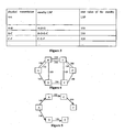
- Figure 3 is a schematic diagram showing the configuration of the cost value of each physical transmission link shown in Figure 2 and the cost value of the corresponding standby LSP;
- Figure 4 is a topology state diagram of a path saved in each node in the solution of the invention.
- Figure 5 is a topology schematic diagram showing the shortest path tree obtained by node A after computation in the solution of the invention
- Figure 6 is a topology schematic diagram showing the shortest path tree obtained by node B after computation in the solution of the invention
- Figure 7 is a topology structural diagram showing the shortest path tree obtained by node A via an update processing after a failure occurs on physical transmission link B-C in the solution of the invention
- Figure 8 is a topology structural diagram showing the shortest path tree obtained by node B via an update processing after failure occurs on physical transmission link B-C in the solution of the invention.
- Figure 9 is a schematic diagram showing a switching process in which the packet flow originally forwarded via physical transmission link A-B is forwarded to a standby LSP (A-D-B) for forwarding after a failure occurs on the physical transmission link A-B in the method for realizing working/standby transmission path according to the invention.
- the invention can be applied to a network for transmitting data via IP, such as DCN or Internet, etc. It will now be illustrated by taking the case in which the invention is applied to a DCN as an example.
- a corresponding standby LSP is configured for each physical transmission link in the DCN, so that when failure occurs on a physical transmission link, a packet transmitted on the physical transmission link can be forwarded to a standby LSP for transmission in time, thus loss of packets can be reduced; at the same time, the maintenance workload and maintenance complexity of the working/standby transmission path can be reduced.
- Figure 1 is a flow chart showing the main principle of the method for realizing working/standby transmission path based on a DCN according to the invention. The process to be realized is as follows:
- Step S10 A standby LSP is configured for each physical transmission link in the DCN.
- the physical transmission link can be composed of an in-fiber control channel, such as ECC; or, the physical transmission link can be composed of an out-of-fiber control channel (such as physical transmission media using out-of-fiber Ethernet as a DCN).
- ECC electronic codec
- out-of-fiber control channel such as physical transmission media using out-of-fiber Ethernet as a DCN.
- the method of the invention can be applied to the physical transmission links composed of either of the two transmission media.
- LSPs of MPLS technology usually support the unidirectional transmission of packets, and the LSP configured for a physical transmission link here should have the property of bidirectional transmission so as to protect the physical transmission link in bidirectional transmission modes respectively, two LSPs in opposite directions need to be configured for each physical transmission link. In other words, a pair of LSPs with opposite transmission directions needs to be configured.
- N is a natural number, which is usually taken as 1
- pairs of LSPs can also be configured for each physical transmission link in the DCN wherein each pair of LSPs has opposite transmission directions.
- a plurality of different LSPs can be configured for a physical transmission link.
- the protected physical transmission link and the physical transmission link through which the standby LSP passes are physically independent; i.e., failure-uncorrelated.
- the physical transmission link through which the configured LSP passes and the protected physical transmission link are mutually independent in a physical layer, and occupy different physical transmission links respectively.
- the failure occurring on the standby LSP can be uncorrelated to the failure occurring on the protected physical transmission link.
- a failure occurs on a physical transmission link will not cause a failure to occur on the standby LSP, so that the object of protecting the physical transmission link via the standby LSP can be attained.
- N pairs of LSPs with opposite transmission directions are configured for a physical transmission link to protect the physical transmission link
- the number of the LSPs configured is in direct proportion to the number of the physical transmission links.
- a configured LSP and a physical transmission link it protects are in a relation of parallel links.
- the physical transmission link and the standby LSP originate from the same source node and end at the same destination node.
- the standby LSP is a long path compared with the physical transmission link to be protected and its routing is not optimized.
- Figure 2 shows a structural topology map of working/standby transmission paths constructed by the method for realizing working/standby transmission path based on a DCN according to the invention.
- A-F represent six network nodes in the DCN, i.e., optical cross-node.
- the physical transmission links formed among these network nodes can be further used for transmitting traffic flow.
- the physical transmission links formed among these nodes include A-B, A-D, B-C, B-D, D-E, C-E, C-F and E-F, and these physical transmission links are failure-uncorrelated.
- these physical transmission links pass through different transmission media such as optical cable, pipe, bridge, and so on, and no failure-related problems will occur.
- These physical transmission links are used for transmitting packets carrying management information and distributed signaling message.
- the cost value of each physical transmission link is 100 (IP routing protocol should ensure that a packet passes through the physical transmission link with the minimum sum of cost values); and nodes A-F all have the MPLS forwarding capacity.
- the process of configuring a standby LSP for each physical transmission link in the DCN can be accomplished according to RSVP-TE (Resource Reservation Protocol-Traffic Extension); or, it can be accomplished according to CR-LDP (Constraint-Based Label Distribution Protocol).
- RSVP-TE Resource Reservation Protocol-Traffic Extension
- CR-LDP Constraint-Based Label Distribution Protocol
- a static LSP can also be realized by configuring a label forwarding table in each node of the DCN respectively.
- RSVP-TE Resource Reservation Protocol-Traffic Extension
- CR-LDP Constraint-Based Label Distribution Protocol
- the cost value of the standby LSP can be configured as greater than the cost value of the physical transmission link to be protected by the standby LSP and less than the sum of the cost value of each physical transmission link through which the standby LSP passes, so that when a failure occurs on the physical transmission link, the packet can be forwarded to the standby LSP for transmission; and when the physical transmission link works normally or recovers to normal, the packet can be automatically forwarded to the physical transmission link for transmission (because the cost value of the physical transmission link is less than that of the standby LSP, and the packet flow transmitted via the LSP originally can be automatically forwarded to the physical transmission link with a smaller cost value for transmission after the routing table is updated).
- the standby LSP of physical transmission link A-B is A-D-B. Because it has been hypothesized above that the cost value of physical transmission link A-B is 100, and the standby LSP (A-D-B) passes through two physical transmission links A-D and D-B, the sum of the cost values of the physical transmission links through which the standby LSP (A-D-B) passes is 200.
- the actual cost value of the standby LSP (A-D-B) can be set as 150, which is between the cost values 100 and 200.
- Figure 3 for the configuration of the cost value of each physical transmission link and the cost value of the corresponding standby LSP shown in Figure 2 .
- Each node in the DCN delivers the configuration of its physical transmission link and the corresponding standby LSP to each of the other nodes in the network via a Link State Advertisement message according to dynamic routing protocols, such as OSPF (Open Shortest Path First).
- OSPF Open Shortest Path First
- each node in the DCN can obtain a path topology state diagram.
- Figure 4 For the specific formation of the path topology state diagram, reference is made to Figure 4 .
- each node in the DCN computes the shortest path to other nodes based on the shortest path algorithm specified in OSPF protocol, taking itself as the starting point, and obtains its IP routing table.
- Figure 5 shows a topology schematic diagram of the shortest path tree obtained by node A after computation according to the method of the invention for realizing working/standby transmission path based on DCN.
- FIG. 6 shows a topology schematic diagram of the shortest path tree obtained by node B after computation according to the method of the invention for realizing working/standby transmission path based on the DCN.
- Each node can construct its IP routing table according to the shortest path tree obtained.
- a next-hop node to which a packet sent from node A to destination node F will be sent is node B, and a physical transmission link for transmitting the packet is A-B.
- OSPF protocol reference is made to RFC2328. In practice, the OSPF protocol can divide a DCN into several areas, which does not have any influence on the implementation of the invention.
- Step S20 it is detected whether a failure occurs on a physical transmission link on which a packet is to be transmitted. If yes, turn to Step S30; otherwise, turn to Step S40.
- the step of detecting whether a failure occurs on the physical transmission link can be accomplished by periodically sending a failure detection message (Hello message) to the DCN via the management plane layer of the DCN, and the Hello message can also detect whether a failure occurs on the standby LSP; and when the physical transmission link is composed of an ECC, it can also detect whether a failure occurs on the physical transmission link via optical network alarm detecting mechanism.
- a failure detection message Hello message
- a Hello message is regularly sent via the management plane layer in the DCN, by this way, working state of the working/standby transmission path in a DCN can be detected. In other words, the specific working state of each physical transmission link and the corresponding standby LSP can be detected. Meanwhile, to reduce a transmission bandwidth occupied during the sending process of the Hello message, the sending period of the Hello message as set cannot be too short. Thesending period is about 10 seconds usually. However, to shorten a route convergence process of each node in the DCN, the sending period of the Hello message should be shortened appropriately; for example, it can be set as 1 second or shorter. In other words, the sending period of the Hello message as a failure discovery mechanism needs to be compromised between the rapidity of failure detection and the dedicated overhead of resources.
- an optical network alarm detecting mechanism based on port level can also taken as a supplementary of the Hello message detecting mechanism.
- working state of a physical transmission link in the DCN can be determined by detecting an alarm message of a regeneration section or multiplex section.
- alarm of LOS (Lost Of Signal) or LOF (Lost Of Frame) appears, it indicates that break-down failure occurs on an associated physical transmission link.
- LOF Lost Of Frame
- the downstream nodes of the physical transmission link on which the failure occurs will detect the failure state immediately.
- An SDH, a Sonet (Synchronous Optical Network), an OTN (Optical Transport Network) and so on can notify the opposite node of the failure information in REI/RDI (Remote Error Indication/ Remote Defect Indication) mode.
- REI/RDI Remote Error Indication/ Remote Defect Indication
- the two end nodes of the physical transmission link on which the failure occurs need to delay delivering the failure information to other nodes in the network using dynamic routing protocol; but when the failure occurs on the physical transmission link and the standby LSP simultaneously, the two end nodes of the physical transmission link on which failure occurs need to deliver the failure information to other nodes in the network in time via dynamic routing protocol.
- the delayed delivery of failure information only applies to the situation in which the failure occurs on the physical transmission link while the standby LSP works normally; in other situations, the failure state of the transmission path needs to be delivered immediately.
- the sending node after the failure occurs on a physical transmission link, because the packet sent by the two end nodes of the physical transmission link on which the failure occurs may not reach the destination node normally, the sending node usually resends the packet for several times.
- the traffic between any two nodes in the DCN and between each node and the network management system will be increased, and at this point, "message storm" may take place in the network.
- the state update information of dynamic routing protocol, based on OSPF is delivered and the routing table is re-computed by each node according to the route state update information at the same time, the communication traffic and computation load will be further increased.
- the two end nodes of the physical transmission link on which the failure occurs delay delivering the failure state information (the actual delay time is set according to specific network situation), so the related node can deliver the route state update information in time on an appropriate occasion, and the IP routing table of each node can be updated and optimized in time, because the "message storm" has ended at this moment. Therefore, the influences of the update process of IP routing tables on the network load can be reduced greatly.
- the packet on physical transmission link B-C will be first switched to the standby LSP (B-D-E-C) of physical transmission link B-C; and each node re-computes its shortest path tree via dynamic route configuration based on OSPF protocol after a time delay, so that an optimized IP routing table that has been refreshed is obtained.
- Figure 7 is a topology structural diagram showing the shortest path tree obtained by node A via an update processing after the failure occurs on physical transmission link B-C according to the method of the invention for realizing working/standby transmission path based on DCN; and
- Figure 8 is a topology structural diagram showing the shortest path tree obtained by node B via an update processing after failure occurs on physical transmission link B-C according to the method of the invention for realizing working/standby transmission path based on the DCN.
- the two end nodes of the physical transmission link on which the failure occurs can diffuse the failure information to other nodes in the network via OSPF protocol or IS-IS (Intermediate System to Intermediate System) protocol.
- OSPF protocol or IS-IS (Intermediate System to Intermediate System) protocol.
- IS-IS Intermediate System to Intermediate System
- ISO Standard No. 8473 Intermediate System to Intermediate System Intra-Domain Routeing Exchange Protocol for use in Conjunction with the Protocol for Providing the Connectionless-mode Network Service.
- Step S30 when it is detected that a failure occurs on the physical transmission link, a packet to be transmitted on the physical transmission link is forwarded to the standby LSP for transmission.
- the standby LSP is also broken down due to failure (the failure information of the standby LSP can also be detected via Hello message of OSPF protocol) after the packet is automatically switched to the standby LSP for transmission when failure occurs on a physical transmission link, the whole-network IP routing table needs to be updated using the process of the prior art via dynamic routing protocol, so as to ensure the reliability of packet transmission in the DCN.
- the packet transmitted on the standby LSP when the packet is transmitted on the standby LSP, if the failure state of the corresponding physical transmission link is eliminated during the process, i.e., the corresponding physical transmission link recovers to normal w6rking state, the packet transmitted on the standby LSP needs to be forwarded to the physical transmission link that recovers to normal for transmission. Because after the physical transmission link is restored, the state of the related physical transmission link changes from Down (which means that the working state of the physical transmission link is abnormal) to Up (which means that the working state of the physical transmission link is normal).
- the situation in which the physical transmission link recovers to normal can also be detected based on the Hello message of OSPF protocol, thus the dynamic route configuration can be updated again via OSPF protocol, so as to update the whole-network IP routing table.
- the cost value of the physical transmission link that recovers to normal is less than that of the standby LSP, the packet flow transmitted on the standby LSP previously will be automatically forwarded to the physical transmission link that has recovered to normal working state for transmission.
- Step S40 when no failure is detected on the physical transmission link, the physical transmission link with a lower cost value will continue to be used for packet transmission.
- forwarding the packet to be transmitted on the physical transmission link on which the failure occurs to the standby LSP for transmission can be accomplished by modifying a list item directed to the physical transmission link on which the failure occurs in the IP routing table saved in a source node on the physical transmission link on which the failure occurs as directed to a list item of the corresponding standby LSP.
- the node can modify the routing table items in which the forwarding interface is directed to the failed physical transmission link in the IP routing table saved therein as directed to the forwarding interface of the corresponding LSP.
- the packet can be forwarded from the physical transmission link on which the failure occurs to a normal LSP for transmission.
- forwarding the packet to be transmitted on the physical transmission link on which the failure occurs to the standby LSP for transmission can also be accomplished by redirecting the packet transmitted on the physical transmission link on which the failure occurs to the standby LSP for transmission in an interface driver of the physical transmission link on which the failure occurs.
- the packet actually transmitted is redirected in the interface driver of the physical transmission link, which means that the packet previously forwarded on the physical transmission link (herein, the packet refers to packet other than OSPF protocol packet, because OSPF protocol packets need to reflect the actual working state of the network) is forwarded to a preconfigured standby LSP for transmission.
- the IP routing table in the DCN does not need to be modified.
- FIG 9 is a schematic diagram showing a switching process in which a packet flow originally forwarded via physical transmission link A-B is forwarded to a standby LSP (A-D-B) for transmission, after a failure occurs on the physical transmission link A-B according to the method of the invention for realizing working/standby transmission path based on the DCN.
- a dashed line path between A and B refers to the standby LSP (A-D-B).
- the forwarding output interface corresponding to the list item, of which the destination address is node B, C or F, in the IP routing table saved in node A needs to be modified as the output interface corresponding to the standby LSP (A-D-B).
- the routing table saved in node A does not need to be modified, and the packet whose destination address is node B, C or F is sent to physical transmission link A-B on which the failure occurs, as directed by the routing table. If the interface driver finds that the failure occurs on the current physical transmission link, it redirects the packet to the preconfigured LSP (A-D-B) for sending.
- the packets forwarded in the mode of redirection do not include OSPF protocol packets.
- node B and node C can know that the physical transmission link B-C has turned from “available” into “unavailable” according to the failure information detected, and the packet on physical transmission link B-C is switched to the corresponding LSP (B-D-E-C) for transmission Because the connectivity of packet forwarding on physical transmission link B-C can be maintained, the routing update state message between node B and node C does not need to be delivered immediately via dynamic routing protocol and the routing table of other nodes does not need to be modified immediately either.
- the optical service influenced by the failure on optical transmission path A-B-C-F is switched to the recovered path A-D-E-F for transmission; when the downstream node F of the optical transmission path A-B-C-F on which failure occurs detects that the optical transmission path is broken down, the downstream node F sends the failure state information to node A.
- the control information which carries the failure state information is forwarded on the DCN through the following process:
- the packet is forwarded to node C via physical transmission link C-F; node C forwards the packet via nodes E and D to node B through the standby LSP of physical transmission link B-C, and this forwarding process is realized via label forwarding in the standard MPLS technology, and for the packet forwarding on IP network layer, in this forwarding process, a packet is directly forwarded via node C to node B (because MPLS forwarding is a forwarding mode between data link layer and network layer, which is invisible to the network layer); then, node B forwards the packet to node A.
- MPLS forwarding is a forwarding mode between data link layer and network layer, which is invisible to the network layer
Landscapes
- Engineering & Computer Science (AREA)
- Computer Networks & Wireless Communication (AREA)
- Signal Processing (AREA)
- Data Exchanges In Wide-Area Networks (AREA)
Claims (13)
- Verfahren zum Herstellen eines Arbeits-/Bereitschaftszustands-Übertragungswegs, das die folgenden Schritte enthält:Konfigurieren (S10) eines Bereitschaftszustands-Etikettvermittlungswegs für eine physikalische Übertragungsverbindung in einem Netz; undWeiterleiten (S30) eines auf der physikalischen Übertragungsverbindung zu übertragenden Pakets zu dem Bereitschaftszustands-Etikettvermittlungsweg für die Übertragung, wenn auf der physikalischen Übertragungsverbindung ein Fehler auftritt,dadurch gekennzeichnet, dass es ferner enthält:wenn der Fehler auf der physikalischen Übertragungsverbindung auftritt, während der Bereitschaftszustands-Etikettvermittlungsweg normal arbeitet, Verzögern der Ausgabe von Fehlerinformationen an andere Knoten durch zwei Endknoten der physikalischen Übertragungsverbindung, auf der der Fehler auftritt, über ein dynamisches Lenkungsprotokoll; wenn der Fehler auf der physikalischen Übertragungsverbindung und auf dem Bereitschaftszustands-Etikettvermittlungsweg gleichzeitig auftritt, unverzögertes Ausgeben von Fehlerinformationen an andere Knoten durch die zwei Endknoten der physikalischen Übertragungsverbindung, auf der der Fehler auftritt, über das dynamische Lenkungsprotokoll.
- Verfahren zum Herstellen eines Arbeits-/Bereitschaftszustands-Übertragungswegs nach Anspruch 1, wobei das Konfigurieren eines Bereitschaftszustands-Etikettvermittlungswegs für die physikalische Übertragungsverbindung durch eines der Folgenden erzielt wird:Verwenden einer Betriebsmittelreservierungsprotokoll-Verkehrserweiterung;Verwenden eines Protokolls zur Etikettverteilung auf Beschränkungsbasis; undKonfigurieren einer Etikettweiterleitungstabelle in jedem Knoten in dem Netz.
- Verfahren zum Herstellen eines Arbeits-/Bereitschaftszustands-Übertragungswegs nach Anspruch 1 oder 2, wobei N Paare von Etikettvermittlungswegen für die physikalische Übertragungsverbindung konfiguriert werden und Übertragungsrichtungen jedes Paars von Etikettvermittlungswegen zueinander entgegengesetzt sind, wobei N eine natürliche Zahl ist.
- Verfahren zum Herstellen eines Arbeits-/Bereitschaftszustands-Übertragungswegs nach Anspruch 1, 2 oder 3, wobei die physikalische Übertragungsverbindung von einer physikalischen Übertragungsverbindung, durch die der Bereitschaftszustands-Etikettvermittlungsweg verläuft, physikalisch unabhängig ist.
- Verfahren zum Herstellen eines Arbeits-/Bereitschaftszustands-Übertragungswegs nach Anspruch 4, das ferner enthält: wenn die physikalische Übertragungsverbindung, auf der der Fehler auftritt, in den Normalzustand zurückkehrt, Weiterleiten des Pakets, das auf dem Bereitschaftszustands-Etikettvermittlungsweg übertragen wird, zu der physikalischen Übertragungsverbindung, die in den Normalzustand zurückgekehrt ist, für die Übertragung.
- Verfahren zum Herstellen eines Arbeits-/Bereitschaftszustands-Übertragungswegs nach Anspruch 4, wobei: ein Kostenwert des Bereitschaftszustands-Etikettvermittlungswegs größer als ein Kostenwert der durch den Bereitschaftszustands-Etikettvermittlungsweg geschützten physikalischen Übertragungsverbindung und kleiner als eine Summe von Kostenwerten von physikalischen Übertragungsverbindungen, durch die der Etikettvermittlungsweg verläuft, konfiguriert wird.
- Verfahren zum Herstellen eines Arbeits-/Bereitschaftszustands-Übertragungswegs nach Anspruch 6, wobei: falls wenigstens zwei Paare von Etikettvermittlungswegen für die physikalische Übertragungsverbindung konfiguriert sind, wenn der Fehler auf der physikalischen Übertragungsverbindung auftritt, Weiterleiten des auf der physikalischen Übertragungsverbindung zu übertragenden Pakets zu einem Bereitschaftszustands-Etikettvermittlungsweg mit einem minimalen Kostenwert für die Übertragung.
- Verfahren zum Herstellen eines Arbeits-/Bereitschaftszustands-Übertragungswegs nach Anspruch 1, 5 oder 6, wobei das Weiterleiten des Pakets, das auf der physikalischen Übertragungsverbindung übertragen werden soll, auf der der Fehler auftritt, zu dem Bereitschaftszustands-Etikettvermittlungsweg für die Übertragung durch eines der Folgenden erzielt wird:Modifizieren eines Listenelements, das zu der physikalischen Übertragungsverbindung gerichtet ist, auf der der Fehler auftritt, in einer Lenkungstabelle, die in einem Quellknoten auf der physikalischen Übertragungsverbindung, auf der der Fehler auftritt, gesichert ist, zu einem Listenelement, das zu dem Bereitschaftszustands-Etikettvermittlungsweg gerichtet ist; undUmlenken eines Pakets, das auf der physikalischen Übertragungsverbindung übertragen wird, auf der der Fehler auftritt, zu dem Bereitschaftszustands-Etikettvermittlungsweg für die Übertragung in einem Schnittstellentreiber der physikalischen Übertragungsverbindung, auf der der Fehler auftritt.
- Verfahren zum Herstellen eines Arbeits-/Bereitschaftszustands-Übertragungswegs nach Anspruch 1, wobei die physikalische Übertragungsverbindung ein faserinterner Steuerkanal oder ein faserexterner Steuerkanal ist.
- Verfahren zum Herstellen eines Arbeits-/Bereitschaftszustands-Übertragungswegs nach Anspruch 9, das ferner das Detektieren, ob ein Fehler auf der physikalischen Übertragungsverbindung und auf dem Bereitschaftszustands-Etikettvermittlungsweg auftritt, durch periodisches Senden einer Fehlerdetektionsnachricht zu dem Netz enthält.
- Verfahren zum Herstellen eines Arbeits-/Bereitschaftszustands-Übertragungswegs nach Anspruch 9, das ferner das Detektieren, ob ein Fehler auf einer physikalischen Übertragungsverbindung auftritt, die aus dem faserinternen Steuerkanal gebildet ist, über einen Mechanismus zum Detektieren eines Alarms in einem optischen Netz enthält.
- Verfahren zum Herstellen eines Arbeits-/Bereitschaftszustands-Übertragungswegs nach Anspruch 1, wobei das Netz ein Netz zum Übertragen von Daten über IP ist.
- Vorrichtung zum Herstellen eines Arbeits-/Bereitschaftszustands-Übertragungswegs, die enthält:Mittel zum Konfigurieren eines Bereitschaftszustands-Etikettvermittlungswegs für eine physikalische Übertragungsverbindung in einem Netz; undMittel zum Weiterleiten eines auf der physikalischen Übertragungsverbindung zu übertragenden Pakets zu dem Bereitschaftszustands-Etikettvermittlungsweg für die Übertragung, wenn auf der physikalischen Übertragungsverbindung ein Fehler auftritt,dadurch gekennzeichnet, dass die Vorrichtung ferner enthält:Mittel zum verzögerten Ausgeben von Fehlerinformationen an andere Knoten durch zwei Endknoten der physikalischen Übertragungsverbindung, auf der der Fehler auftritt, über ein dynamisches Lenkungsprotokoll, wenn der Fehler auf der physikalischen Übertragungsverbindung auftritt, während der Bereitschaftszustands-Etikettvermittlungsweg normal arbeitet, und zum unverzögerten Ausgeben von Fehlerinformationen an andere Knoten durch die zwei Endknoten der physikalischen Übertragungsverbindung, auf der der Fehler auftritt, über das dynamische Lenkungsprotokoll, wenn der Fehler auf der physikalischen Übertragungsverbindung und auf dem Bereitschaftszustands-Etikettvermittlungsweg gleichzeitig auftritt.
Applications Claiming Priority (2)
| Application Number | Priority Date | Filing Date | Title |
|---|---|---|---|
| CN2005100048459A CN1816035B (zh) | 2005-02-02 | 2005-02-02 | 基于数据通信网的主备传输路径实现方法 |
| PCT/CN2006/000170 WO2006081767A1 (en) | 2005-02-02 | 2006-01-26 | A method for implementing master and backup transmission path |
Publications (3)
| Publication Number | Publication Date |
|---|---|
| EP1845656A1 EP1845656A1 (de) | 2007-10-17 |
| EP1845656A4 EP1845656A4 (de) | 2008-05-28 |
| EP1845656B1 true EP1845656B1 (de) | 2011-07-13 |
Family
ID=36776970
Family Applications (1)
| Application Number | Title | Priority Date | Filing Date |
|---|---|---|---|
| EP06705591A Expired - Lifetime EP1845656B1 (de) | 2005-02-02 | 2006-01-26 | Verfahren zur implementierung eines master- und backup-übertragungsweges |
Country Status (6)
| Country | Link |
|---|---|
| US (1) | US20070286069A1 (de) |
| EP (1) | EP1845656B1 (de) |
| CN (1) | CN1816035B (de) |
| AT (1) | ATE516638T1 (de) |
| ES (1) | ES2366957T3 (de) |
| WO (1) | WO2006081767A1 (de) |
Families Citing this family (26)
| Publication number | Priority date | Publication date | Assignee | Title |
|---|---|---|---|---|
| US7606143B2 (en) * | 2007-02-28 | 2009-10-20 | Embarq Corporation | System and method for advanced fail-over for packet label swapping |
| US20090052444A1 (en) * | 2007-08-24 | 2009-02-26 | At&T Bls Intellectual Property, Inc. | Methods, systems, and computer program products for providing multi-service communication networks and related core networks |
| CN101159690B (zh) * | 2007-11-19 | 2010-10-27 | 杭州华三通信技术有限公司 | 多协议标签交换转发方法、装置及标签交换路径管理模块 |
| CN101453414B (zh) * | 2007-11-30 | 2011-08-10 | 华为技术有限公司 | 点到多点标签交换路径的头节点保护方法、系统和设备 |
| WO2009106153A1 (en) * | 2008-02-29 | 2009-09-03 | Telefonaktiebolaget Lm Ericsson (Publ) | Communication network |
| US8155028B2 (en) * | 2008-03-17 | 2012-04-10 | Alcatel Lucent | Method and apparatus for providing full logical connectivity in MPLS networks |
| US8203938B2 (en) * | 2008-05-22 | 2012-06-19 | Level 3 Communications, Llc | Multi-router IGP fate sharing |
| JP2009296230A (ja) * | 2008-06-04 | 2009-12-17 | Nec Corp | 伝送ネットワーク、伝送装置、伝送ネットワークの回線切替方法及びプログラム |
| CN101309230B (zh) * | 2008-06-27 | 2010-12-08 | 迈普通信技术股份有限公司 | 多协议标签交换网络传输路径切换报文秩序控制方法 |
| EP2180636B1 (de) | 2008-10-23 | 2011-12-28 | Alcatel Lucent | Verfahren zur Signalisierung eines unidirektionalen Fehlers einer paketgeschalteten Verknüpfung |
| JP5251538B2 (ja) * | 2009-01-20 | 2013-07-31 | 富士通株式会社 | 異常箇所特定プログラム、異常箇所特定装置、異常箇所特定方法 |
| US8514876B2 (en) * | 2009-08-11 | 2013-08-20 | Cisco Technology, Inc. | Method and apparatus for sequencing operations for an incoming interface check in data center ethernet |
| US8687653B2 (en) * | 2009-10-30 | 2014-04-01 | Brocade Communications Systems, Inc. | Tunnel path MTU discovery |
| US8233387B2 (en) | 2009-11-06 | 2012-07-31 | Telefonaktiebolaget L M Ericsson (Publ) | Disjoint path computation algorithm |
| JP5494110B2 (ja) * | 2010-03-29 | 2014-05-14 | 富士通株式会社 | ネットワークの通信経路推定方法、通信経路推定プログラム及び監視装置 |
| US8848518B2 (en) * | 2010-05-06 | 2014-09-30 | Verizon Patent And Licensing Inc. | System and method for providing notification of a change in path condition |
| US9813257B2 (en) * | 2010-09-10 | 2017-11-07 | Extreme Networks, Inc. | Access network dual path connectivity |
| DE102013204042A1 (de) * | 2013-03-08 | 2014-09-11 | Siemens Aktiengesellschaft | Verfahren zur Übertragung von Datenpaketen in einem Datennetz aus einer Vielzahl von Netzknoten |
| EP2784992B1 (de) * | 2013-03-28 | 2016-11-30 | Mitsubishi Electric R&D Centre Europe B.V. | Verfahren und System zur Konfiguration von Knotenvorrichtungen eines Maschenkommunikationsnetzwerks bei der Detektion eines Verbindungsfehlers oder einer Verbindungswiederherstellung |
| KR101881435B1 (ko) * | 2014-01-14 | 2018-07-24 | 후아웨이 테크놀러지 컴퍼니 리미티드 | 이더넷 신호 전송 방법 및 스케줄링 방법, 및 그 장치 및 시스템 |
| CN107171820B (zh) * | 2016-03-08 | 2019-12-31 | 北京京东尚科信息技术有限公司 | 信息传输、发送、获取方法和装置 |
| US9985870B2 (en) * | 2016-07-29 | 2018-05-29 | Nanning Fugui Precision Industrial Co., Ltd. | Network service method and system based on software defined networking |
| CN109672616A (zh) * | 2018-12-27 | 2019-04-23 | 北京奇安信科技有限公司 | 数据传输方法、装置、设备及介质 |
| CN112994929A (zh) * | 2021-02-04 | 2021-06-18 | 北京西鼎众合技术有限公司 | 一种基于主备链路切换的网络传输方法和系统 |
| US20240007392A1 (en) * | 2022-06-29 | 2024-01-04 | Cisco Technology, Inc. | Opportunistic label switched paths to ensure acceptable application experience |
| CN119512827A (zh) * | 2023-08-25 | 2025-02-25 | 华为技术有限公司 | 分布式计算系统和用于分布式计算系统的故障处理方法 |
Family Cites Families (24)
| Publication number | Priority date | Publication date | Assignee | Title |
|---|---|---|---|---|
| CA2310872A1 (en) | 1999-12-22 | 2001-06-22 | Nortel Networks Corporation | Automatic protection switching using link-level redundancy supporting multi-protocol label switching |
| US6996065B2 (en) * | 2000-07-06 | 2006-02-07 | Lucent Technologies Inc. | Dynamic backup routing of network tunnel paths for local restoration in a packet network |
| KR100725005B1 (ko) * | 2000-11-22 | 2007-06-04 | 주식회사 케이티 | 다중 프로토콜 레이블 스위칭 망에서의 고속 재라우팅 방법 |
| US7280526B2 (en) * | 2001-01-18 | 2007-10-09 | Lucent Technologies Inc. | Fast and scalable approximation methods for finding minimum cost flows with shared recovery strategies, and system using same |
| WO2002065306A1 (en) * | 2001-02-12 | 2002-08-22 | Maple Optical Systems, Inc. | System and method for fault notification in a data communication network |
| US20030063580A1 (en) | 2001-09-28 | 2003-04-03 | Russell Pond | Packetized voice messaging |
| US7039005B2 (en) * | 2001-10-02 | 2006-05-02 | Fujitsu Limited | Protection switching in a communications network employing label switching |
| EP1318648B1 (de) * | 2001-12-07 | 2006-02-08 | Nortel Networks Limited | Schnelles Pfadwiederherstellungsverfahren in Label-Vermittlungsnetzwerken und Netzwerkanordnung zur Ausführung des Verfahrens |
| US20030117950A1 (en) * | 2001-12-26 | 2003-06-26 | Huang Gail G | Link redial for mesh protection |
| US7496096B1 (en) * | 2002-01-31 | 2009-02-24 | Cisco Technology, Inc. | Method and system for defining hardware routing paths for networks having IP and MPLS paths |
| US7230913B1 (en) * | 2002-06-11 | 2007-06-12 | Cisco Technology, Inc. | MPLS fast reroute without full mesh traffic engineering |
| CN1754352B (zh) * | 2003-02-21 | 2011-09-21 | 日本电信电话株式会社 | 用于进行通信网络中的通道的故障救济的装置和方法 |
| US7697417B2 (en) * | 2003-07-18 | 2010-04-13 | Alcatel-Lucent Usa Inc. | Methods and devices for re-routing MPLS traffic |
| IL158656A (en) * | 2003-10-29 | 2009-02-11 | Eci Telecom Ltd | Rerouting mpls traffic in ring networks |
| CN100502528C (zh) * | 2004-06-08 | 2009-06-17 | 华为技术有限公司 | 实现自动交换光网络中光连接间的关联的方法 |
| CN100334857C (zh) * | 2004-09-27 | 2007-08-29 | 华为技术有限公司 | 一种环网及其业务实现方法 |
| US7406032B2 (en) * | 2005-01-06 | 2008-07-29 | At&T Corporation | Bandwidth management for MPLS fast rerouting |
| CN1327673C (zh) * | 2005-01-29 | 2007-07-18 | 华为技术有限公司 | 一种多协议标签交换网络的数据传输方法及系统 |
| US9306831B2 (en) * | 2005-02-14 | 2016-04-05 | Cisco Technology, Inc. | Technique for efficient load balancing of TE-LSPs |
| GB0519648D0 (en) * | 2005-09-27 | 2005-11-02 | Roke Manor Research | Resilient path protocol |
| CN100414942C (zh) * | 2005-09-27 | 2008-08-27 | 华为技术有限公司 | 业务转发路由的恢复方法 |
| US7675860B2 (en) * | 2006-02-27 | 2010-03-09 | Cisco Technology, Inc. | Method and apparatus for determining a preferred backup tunnel to protect point-to-multipoint label switch paths |
| US7808887B2 (en) * | 2006-08-23 | 2010-10-05 | Alcatel Lucent | Bridge/router and method for avoiding packet replication during a failure in a network |
| JP5135748B2 (ja) * | 2006-09-27 | 2013-02-06 | 富士通株式会社 | 伝送装置及びパス設定方法 |
-
2005
- 2005-02-02 CN CN2005100048459A patent/CN1816035B/zh not_active Expired - Fee Related
-
2006
- 2006-01-26 ES ES06705591T patent/ES2366957T3/es not_active Expired - Lifetime
- 2006-01-26 WO PCT/CN2006/000170 patent/WO2006081767A1/zh not_active Ceased
- 2006-01-26 EP EP06705591A patent/EP1845656B1/de not_active Expired - Lifetime
- 2006-01-26 AT AT06705591T patent/ATE516638T1/de not_active IP Right Cessation
-
2007
- 2007-08-02 US US11/832,744 patent/US20070286069A1/en not_active Abandoned
Also Published As
| Publication number | Publication date |
|---|---|
| CN1816035B (zh) | 2010-07-07 |
| EP1845656A1 (de) | 2007-10-17 |
| EP1845656A4 (de) | 2008-05-28 |
| US20070286069A1 (en) | 2007-12-13 |
| CN1816035A (zh) | 2006-08-09 |
| ATE516638T1 (de) | 2011-07-15 |
| WO2006081767A1 (en) | 2006-08-10 |
| ES2366957T3 (es) | 2011-10-27 |
Similar Documents
| Publication | Publication Date | Title |
|---|---|---|
| US20070286069A1 (en) | Method For Implementing Working/Standby Transmission Path | |
| EP1111860B1 (de) | Automatischer Schutz von Vermittlungswegen mit Redundanz auf Verbindungsebene zur Unterstützung von MPLS | |
| ES2363410T3 (es) | Método, dispositivo y sistema para la conmutación de tráfico en ingeniería de tráfico de conmutación multiprotocolo por etiqueta. | |
| CN101286892B (zh) | 进行业务恢复的装置和方法 | |
| US7710860B2 (en) | Data relay apparatus and data relay method | |
| US20120207017A1 (en) | Recovery mechanism for point-to-multipoint traffic | |
| EP2495918B1 (de) | Verfahren, system und knotenvorrichtung zur herstellung eines label-schaltpfades | |
| US7012887B2 (en) | Method for restoring diversely routed circuits | |
| EP2866394B1 (de) | Verfahren und vorrichtung zum senden von informationen über domänenübergreifende fehler | |
| US20030117950A1 (en) | Link redial for mesh protection | |
| US10250492B2 (en) | Segment recovery in connection-oriented network | |
| CN101459535A (zh) | 进行业务恢复的装置和方法 | |
| WO2012088967A1 (zh) | 一种网络恢复方法和装置 | |
| WO2011157130A2 (zh) | 路径建立方法和装置 | |
| JP2011528524A (ja) | パケット交換網における擬似ワイヤの確立 | |
| EP1921797B1 (de) | Verfahren und vorrichtung zur wiederherstellung nach einem aussergewöhnlichen löschvorgang in einem lsp (label-switched path) eines optischen netzes | |
| CN101459565B (zh) | 一种复用段保护业务的恢复方法、装置和网络节点 | |
| WO2008119294A1 (en) | Method and equipment for restoring network business | |
| CN101431466A (zh) | 快速重路由方法及标签交换路由器 | |
| EP2658177B1 (de) | Verfahren zur erkennung von tunnelfehlern und verkehrsmanipulationsknoten | |
| WO2012106976A1 (zh) | 一种故障保护方法及设备 | |
| CN104852809A (zh) | 信号劣化故障的处理方法及系统 | |
| CN1499747A (zh) | 一种实现智能光网络保护和恢复的方法 | |
| CN101374106A (zh) | 一种mpls lsp上转发数据包的方法、网络节点和系统 | |
| CN101610203A (zh) | 实现组播重路由的方法、装置及系统 |
Legal Events
| Date | Code | Title | Description |
|---|---|---|---|
| PUAI | Public reference made under article 153(3) epc to a published international application that has entered the european phase |
Free format text: ORIGINAL CODE: 0009012 |
|
| 17P | Request for examination filed |
Effective date: 20070808 |
|
| AK | Designated contracting states |
Kind code of ref document: A1 Designated state(s): AT BE BG CH CY CZ DE DK EE ES FI FR GB GR HU IE IS IT LI LT LU LV MC NL PL PT RO SE SI SK TR |
|
| DAX | Request for extension of the european patent (deleted) | ||
| A4 | Supplementary search report drawn up and despatched |
Effective date: 20080424 |
|
| 17Q | First examination report despatched |
Effective date: 20080911 |
|
| GRAP | Despatch of communication of intention to grant a patent |
Free format text: ORIGINAL CODE: EPIDOSNIGR1 |
|
| GRAS | Grant fee paid |
Free format text: ORIGINAL CODE: EPIDOSNIGR3 |
|
| GRAA | (expected) grant |
Free format text: ORIGINAL CODE: 0009210 |
|
| AK | Designated contracting states |
Kind code of ref document: B1 Designated state(s): AT BE BG CH CY CZ DE DK EE ES FI FR GB GR HU IE IS IT LI LT LU LV MC NL PL PT RO SE SI SK TR |
|
| REG | Reference to a national code |
Ref country code: GB Ref legal event code: FG4D |
|
| REG | Reference to a national code |
Ref country code: CH Ref legal event code: EP |
|
| REG | Reference to a national code |
Ref country code: IE Ref legal event code: FG4D |
|
| REG | Reference to a national code |
Ref country code: DE Ref legal event code: R096 Ref document number: 602006023047 Country of ref document: DE Effective date: 20110901 |
|
| REG | Reference to a national code |
Ref country code: ES Ref legal event code: FG2A Ref document number: 2366957 Country of ref document: ES Kind code of ref document: T3 Effective date: 20111027 |
|
| REG | Reference to a national code |
Ref country code: NL Ref legal event code: VDEP Effective date: 20110713 |
|
| REG | Reference to a national code |
Ref country code: AT Ref legal event code: MK05 Ref document number: 516638 Country of ref document: AT Kind code of ref document: T Effective date: 20110713 |
|
| PG25 | Lapsed in a contracting state [announced via postgrant information from national office to epo] |
Ref country code: FI Free format text: LAPSE BECAUSE OF FAILURE TO SUBMIT A TRANSLATION OF THE DESCRIPTION OR TO PAY THE FEE WITHIN THE PRESCRIBED TIME-LIMIT Effective date: 20110713 Ref country code: PT Free format text: LAPSE BECAUSE OF FAILURE TO SUBMIT A TRANSLATION OF THE DESCRIPTION OR TO PAY THE FEE WITHIN THE PRESCRIBED TIME-LIMIT Effective date: 20111114 Ref country code: IS Free format text: LAPSE BECAUSE OF FAILURE TO SUBMIT A TRANSLATION OF THE DESCRIPTION OR TO PAY THE FEE WITHIN THE PRESCRIBED TIME-LIMIT Effective date: 20111113 Ref country code: LT Free format text: LAPSE BECAUSE OF FAILURE TO SUBMIT A TRANSLATION OF THE DESCRIPTION OR TO PAY THE FEE WITHIN THE PRESCRIBED TIME-LIMIT Effective date: 20110713 Ref country code: NL Free format text: LAPSE BECAUSE OF FAILURE TO SUBMIT A TRANSLATION OF THE DESCRIPTION OR TO PAY THE FEE WITHIN THE PRESCRIBED TIME-LIMIT Effective date: 20110713 Ref country code: SE Free format text: LAPSE BECAUSE OF FAILURE TO SUBMIT A TRANSLATION OF THE DESCRIPTION OR TO PAY THE FEE WITHIN THE PRESCRIBED TIME-LIMIT Effective date: 20110713 |
|
| PG25 | Lapsed in a contracting state [announced via postgrant information from national office to epo] |
Ref country code: SI Free format text: LAPSE BECAUSE OF FAILURE TO SUBMIT A TRANSLATION OF THE DESCRIPTION OR TO PAY THE FEE WITHIN THE PRESCRIBED TIME-LIMIT Effective date: 20110713 Ref country code: LV Free format text: LAPSE BECAUSE OF FAILURE TO SUBMIT A TRANSLATION OF THE DESCRIPTION OR TO PAY THE FEE WITHIN THE PRESCRIBED TIME-LIMIT Effective date: 20110713 Ref country code: AT Free format text: LAPSE BECAUSE OF FAILURE TO SUBMIT A TRANSLATION OF THE DESCRIPTION OR TO PAY THE FEE WITHIN THE PRESCRIBED TIME-LIMIT Effective date: 20110713 Ref country code: CY Free format text: LAPSE BECAUSE OF FAILURE TO SUBMIT A TRANSLATION OF THE DESCRIPTION OR TO PAY THE FEE WITHIN THE PRESCRIBED TIME-LIMIT Effective date: 20110713 Ref country code: PL Free format text: LAPSE BECAUSE OF FAILURE TO SUBMIT A TRANSLATION OF THE DESCRIPTION OR TO PAY THE FEE WITHIN THE PRESCRIBED TIME-LIMIT Effective date: 20110713 Ref country code: GR Free format text: LAPSE BECAUSE OF FAILURE TO SUBMIT A TRANSLATION OF THE DESCRIPTION OR TO PAY THE FEE WITHIN THE PRESCRIBED TIME-LIMIT Effective date: 20111014 |
|
| PG25 | Lapsed in a contracting state [announced via postgrant information from national office to epo] |
Ref country code: SK Free format text: LAPSE BECAUSE OF FAILURE TO SUBMIT A TRANSLATION OF THE DESCRIPTION OR TO PAY THE FEE WITHIN THE PRESCRIBED TIME-LIMIT Effective date: 20110713 Ref country code: CZ Free format text: LAPSE BECAUSE OF FAILURE TO SUBMIT A TRANSLATION OF THE DESCRIPTION OR TO PAY THE FEE WITHIN THE PRESCRIBED TIME-LIMIT Effective date: 20110713 |
|
| PLBE | No opposition filed within time limit |
Free format text: ORIGINAL CODE: 0009261 |
|
| STAA | Information on the status of an ep patent application or granted ep patent |
Free format text: STATUS: NO OPPOSITION FILED WITHIN TIME LIMIT |
|
| PG25 | Lapsed in a contracting state [announced via postgrant information from national office to epo] |
Ref country code: EE Free format text: LAPSE BECAUSE OF FAILURE TO SUBMIT A TRANSLATION OF THE DESCRIPTION OR TO PAY THE FEE WITHIN THE PRESCRIBED TIME-LIMIT Effective date: 20110713 Ref country code: RO Free format text: LAPSE BECAUSE OF FAILURE TO SUBMIT A TRANSLATION OF THE DESCRIPTION OR TO PAY THE FEE WITHIN THE PRESCRIBED TIME-LIMIT Effective date: 20110713 |
|
| 26N | No opposition filed |
Effective date: 20120416 |
|
| PG25 | Lapsed in a contracting state [announced via postgrant information from national office to epo] |
Ref country code: DK Free format text: LAPSE BECAUSE OF FAILURE TO SUBMIT A TRANSLATION OF THE DESCRIPTION OR TO PAY THE FEE WITHIN THE PRESCRIBED TIME-LIMIT Effective date: 20110713 |
|
| REG | Reference to a national code |
Ref country code: DE Ref legal event code: R097 Ref document number: 602006023047 Country of ref document: DE Effective date: 20120416 |
|
| PG25 | Lapsed in a contracting state [announced via postgrant information from national office to epo] |
Ref country code: MC Free format text: LAPSE BECAUSE OF NON-PAYMENT OF DUE FEES Effective date: 20120131 |
|
| REG | Reference to a national code |
Ref country code: CH Ref legal event code: PL |
|
| REG | Reference to a national code |
Ref country code: IE Ref legal event code: MM4A |
|
| PG25 | Lapsed in a contracting state [announced via postgrant information from national office to epo] |
Ref country code: CH Free format text: LAPSE BECAUSE OF NON-PAYMENT OF DUE FEES Effective date: 20120131 Ref country code: LI Free format text: LAPSE BECAUSE OF NON-PAYMENT OF DUE FEES Effective date: 20120131 |
|
| PG25 | Lapsed in a contracting state [announced via postgrant information from national office to epo] |
Ref country code: IE Free format text: LAPSE BECAUSE OF NON-PAYMENT OF DUE FEES Effective date: 20120126 |
|
| PG25 | Lapsed in a contracting state [announced via postgrant information from national office to epo] |
Ref country code: BG Free format text: LAPSE BECAUSE OF FAILURE TO SUBMIT A TRANSLATION OF THE DESCRIPTION OR TO PAY THE FEE WITHIN THE PRESCRIBED TIME-LIMIT Effective date: 20111013 |
|
| PG25 | Lapsed in a contracting state [announced via postgrant information from national office to epo] |
Ref country code: TR Free format text: LAPSE BECAUSE OF FAILURE TO SUBMIT A TRANSLATION OF THE DESCRIPTION OR TO PAY THE FEE WITHIN THE PRESCRIBED TIME-LIMIT Effective date: 20110713 |
|
| PG25 | Lapsed in a contracting state [announced via postgrant information from national office to epo] |
Ref country code: LU Free format text: LAPSE BECAUSE OF NON-PAYMENT OF DUE FEES Effective date: 20120126 |
|
| PG25 | Lapsed in a contracting state [announced via postgrant information from national office to epo] |
Ref country code: HU Free format text: LAPSE BECAUSE OF FAILURE TO SUBMIT A TRANSLATION OF THE DESCRIPTION OR TO PAY THE FEE WITHIN THE PRESCRIBED TIME-LIMIT Effective date: 20060126 |
|
| REG | Reference to a national code |
Ref country code: FR Ref legal event code: PLFP Year of fee payment: 11 |
|
| REG | Reference to a national code |
Ref country code: FR Ref legal event code: PLFP Year of fee payment: 12 |
|
| REG | Reference to a national code |
Ref country code: FR Ref legal event code: PLFP Year of fee payment: 13 |
|
| REG | Reference to a national code |
Ref country code: DE Ref legal event code: R079 Ref document number: 602006023047 Country of ref document: DE Free format text: PREVIOUS MAIN CLASS: H04L0012240000 Ipc: H04L0041000000 |
|
| PGFP | Annual fee paid to national office [announced via postgrant information from national office to epo] |
Ref country code: GB Payment date: 20211206 Year of fee payment: 17 Ref country code: FR Payment date: 20211214 Year of fee payment: 17 |
|
| PGFP | Annual fee paid to national office [announced via postgrant information from national office to epo] |
Ref country code: BE Payment date: 20211221 Year of fee payment: 17 |
|
| PGFP | Annual fee paid to national office [announced via postgrant information from national office to epo] |
Ref country code: DE Payment date: 20211130 Year of fee payment: 17 |
|
| PGFP | Annual fee paid to national office [announced via postgrant information from national office to epo] |
Ref country code: IT Payment date: 20211213 Year of fee payment: 17 Ref country code: ES Payment date: 20220203 Year of fee payment: 17 |
|
| REG | Reference to a national code |
Ref country code: DE Ref legal event code: R119 Ref document number: 602006023047 Country of ref document: DE |
|
| GBPC | Gb: european patent ceased through non-payment of renewal fee |
Effective date: 20230126 |
|
| REG | Reference to a national code |
Ref country code: BE Ref legal event code: MM Effective date: 20230131 |
|
| PG25 | Lapsed in a contracting state [announced via postgrant information from national office to epo] |
Ref country code: GB Free format text: LAPSE BECAUSE OF NON-PAYMENT OF DUE FEES Effective date: 20230126 Ref country code: DE Free format text: LAPSE BECAUSE OF NON-PAYMENT OF DUE FEES Effective date: 20230801 |
|
| PG25 | Lapsed in a contracting state [announced via postgrant information from national office to epo] |
Ref country code: FR Free format text: LAPSE BECAUSE OF NON-PAYMENT OF DUE FEES Effective date: 20230131 Ref country code: BE Free format text: LAPSE BECAUSE OF NON-PAYMENT OF DUE FEES Effective date: 20230131 |
|
| PG25 | Lapsed in a contracting state [announced via postgrant information from national office to epo] |
Ref country code: IT Free format text: LAPSE BECAUSE OF NON-PAYMENT OF DUE FEES Effective date: 20230126 |
|
| REG | Reference to a national code |
Ref country code: ES Ref legal event code: FD2A Effective date: 20240402 |
|
| PG25 | Lapsed in a contracting state [announced via postgrant information from national office to epo] |
Ref country code: ES Free format text: LAPSE BECAUSE OF NON-PAYMENT OF DUE FEES Effective date: 20230127 |
|
| PG25 | Lapsed in a contracting state [announced via postgrant information from national office to epo] |
Ref country code: ES Free format text: LAPSE BECAUSE OF NON-PAYMENT OF DUE FEES Effective date: 20230127 |