EP1845752A2 - Plattenheizkörper für Räume Heizung - Google Patents
Plattenheizkörper für Räume Heizung Download PDFInfo
- Publication number
- EP1845752A2 EP1845752A2 EP07425197A EP07425197A EP1845752A2 EP 1845752 A2 EP1845752 A2 EP 1845752A2 EP 07425197 A EP07425197 A EP 07425197A EP 07425197 A EP07425197 A EP 07425197A EP 1845752 A2 EP1845752 A2 EP 1845752A2
- Authority
- EP
- European Patent Office
- Prior art keywords
- slab
- stone
- panel
- resistive heating
- ceramic
- Prior art date
- Legal status (The legal status is an assumption and is not a legal conclusion. Google has not performed a legal analysis and makes no representation as to the accuracy of the status listed.)
- Withdrawn
Links
Images
Classifications
-
- H—ELECTRICITY
- H05—ELECTRIC TECHNIQUES NOT OTHERWISE PROVIDED FOR
- H05B—ELECTRIC HEATING; ELECTRIC LIGHT SOURCES NOT OTHERWISE PROVIDED FOR; CIRCUIT ARRANGEMENTS FOR ELECTRIC LIGHT SOURCES, IN GENERAL
- H05B3/00—Ohmic-resistance heating
- H05B3/20—Heating elements having extended surface area substantially in a two-dimensional [2D] plane, e.g. plate-heater
- H05B3/22—Heating elements having extended surface area substantially in a two-dimensional [2D] plane, e.g. plate-heater non-flexible
- H05B3/28—Heating elements having extended surface area substantially in a two-dimensional [2D] plane, e.g. plate-heater non-flexible heating conductor embedded in insulating material
- H05B3/283—Heating elements having extended surface area substantially in a two-dimensional [2D] plane, e.g. plate-heater non-flexible heating conductor embedded in insulating material the insulating material being an inorganic material, e.g. ceramic
-
- F—MECHANICAL ENGINEERING; LIGHTING; HEATING; WEAPONS; BLASTING
- F24—HEATING; RANGES; VENTILATING
- F24H—FLUID HEATERS, e.g. WATER OR AIR HEATERS, HAVING HEAT-GENERATING MEANS, e.g. HEAT PUMPS, IN GENERAL
- F24H7/00—Storage heaters, i.e. heaters in which the energy is stored as heat in masses for subsequent release
- F24H7/06—Storage heaters, i.e. heaters in which the energy is stored as heat in masses for subsequent release the released heat being radiated
- F24H7/062—Storage heaters, i.e. heaters in which the energy is stored as heat in masses for subsequent release the released heat being radiated with electrical energy supply
Definitions
- the present invention relates to a panel for the heating of environments made up of a radiant element on the rear surface on which there are heating resistive elements.
- Heating panels of this type are known where a radiant element consists of a steel plate or metal sheet having a front surface, with a possible decoration in order to embellish the panel, and a rear surface onto which there are heating resistive elements.
- the heating elements are essentially electrical wire resistances or film resistive elements fed by the standard voltage of an electrical system, i.e. 220-240V.
- these elements By electrically feeding the resistive elements, these elements warm due to the Joule effect, and transmit the heat to the steel plate that, due to its well-known heat conductive propriety, it warms and irradiates heat into the environment.
- the outer surface of the steel plate reaches a temperature of approximately 80 °C, an ideal temperature for heating. In fact, this temperature is similar to those of the radiators, thus allowing an efficient heating of the environment, but at the same time, avoiding bums in case of accidental or brief physical contact.
- the metal is also a good conductor of electricity and, since the heating resistive elements are fed by the system electrical voltage of 220-240V, there are electrical risks due to the accidental contacts with parts in tension, in case failures or malfunctionings of the panel should occur.
- the metallic plate is not able to reach dangerous voltages for people, however, other problems arise.
- the resistive heating element whatever it is, is made of a real and proper resistance and of an insulating protective element. Therefore, the panel acts exactly as if it were a condenser or a capacitor where one plate is the steel plate and the other one is the electrical resistance, whereas the dielectric material interposed between the two plates is the insulating protective element.
- Another drawback is due to the fact that the metallic plate is thin and that the specifc heat of the metallic material is very low, therefore the thermal capacity for accumulating heat is extremely reduced. Then, as soon as the feeding of the panel is switched off, the emission of the heat is interrupted, thus causing an unpleasant sensation of cold in the room.
- the aim of the present invention is to make a panel for the heating of environments which is able to overcome the drawbacks described in the above-mentioned prior art.
- a panel which is simple in costruction and efficient in the operation. Moreover, it does not have electrical risks for people, even in case of failures and malfunctionings. It must have a sufficient thermal capacity in order to accumulate heat and then be able to release it when the panel is not electrically fed. The panel must also be able to withstand thermal shocks to which it is subjected.
- Another aim is to obtain a heating panel which is very aesthetically appealing.
- a panel for the heating of environments of the initially described type comprising a radiant covering element having a front radiant surface opposite a rear surface and film resistive heating means applied onto said rear surface of said radiant covering element, characterized in that said radiant covering element is a stone or ceramic slab.
- the stone or ceramic material namely a material with a low electrical conductivity and that is an electrically insulating material, there is no electrical risk for people, even in the event that the covering slab of stone or ceramic material should come into contact with electrical parts under tension.
- the panel is so intrinsically safe and thus does not need any kind of expedient or electrical safety device in order to ensure people's safety whaterever occurs.
- the stone or the ceramic material has a specific heat quite high, then it easily accumulates heat for releasing it in case of necessity when the panel is not for a moment electrically fed, thus operating as a thermal accumulator. Therefore, the new panel does not require any kind of device for accumulating heat, since it is sufficient the heat accumulated in the stone or ceramic material.
- the stone or ceramic slab has a thickness betweeen 3mm and 3cm., preferably 1cm, in order to ensure the maximun safety from the electrical point of view and an optimum capacity for accumulating heat.
- materials which are bad conductors of electricity are also bad conductors of heat, such as the stone or ceramic material which is not a good conductor of heat, in contrast, for example with the metallic materials.
- the panel is much more physically attractive.
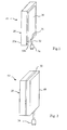
- a heating panel for environments is entirely indicated with reference 10 comprising a stone or ceramic slab 20 and a film resistive heating element 30.
- the stone or ceramic slab 20 has a radiant front surface 20a and an opposite rear surface 20b where the resistive heating element 30 is applied.
- the stone slab may be of natural stone, such as marble, granite, porphyry and so on, but more preferably an agglomerate stone slab.
- An aggglomerate stone slab is usually obtained by a process which consists of a first step of mixing to form a mix made up of a granular inert material, an organic or inorganic binder and a filler. These materials are intimately mixed together in order to obtain a homogeneous mix.
- the next step consists in distributing the mix thus prepared in a mould and, at last, the mix is compacted by a press (which is optionally placed into a vacuum room) and laying the mould on a vibrating plate.
- the compacted slab underogoes a hardening step by means of catalysis of the organic binder (such as a resin) or setting of the inorganic binder such as cement.
- An agglomerate stone slab is preferred to a natural stone slab, since it has a homogeneous structure and there is no defects. Therefore, it is extremely resistant both to mechanical stresses and thermal shocks, in contrast with what occurs with natural stone where there are always flaws such as cavities and cracks which make the stone slab very brittle. Moreover, the use of a binder, makes the agglomerate stone slab more resistant.
- a stone or ceramic slab has a thickness between 3mm and 3 cm, but preferably a thickness of 1 cm. Obviously, the stone or ceramic slab may have different dimensions, both in length or in width.
- the film heating resistive element 30 is composed of pellicular resistive elements of "etched foiled” or PTF type (polymer thick film); the latter is formed by a lower layer of insulating material which forms the support on which, by means of depositing methods, resistive ink is applied which is covered by an upper layer of insulating material too.
- the resistive ink layer is laid down in strips and may have characteristics of PTC type (positive temperature coefficient) whereby as the temperature increases, the electric resistance value increases, thus limiting by itself the current intensity avoiding dangerous overheating.
- PTC type positive temperature coefficient
- the resistive heating element 30 is applied on the stone or ceramic slab 20 by biadhesive means, that is a tape which is adhesive on both sides, which is previously applied to the heating element 30. Subsequently, the surface of heating element 30 with the biadhesive tape is applied on the rear surface 20b of the slab 20.
- the surface of the resistive heating element 30 has an area essentialy equal to the area of the rear surface 20b of the stone or ceramic slab 20, so as to efficiently heat the slab 20 on the whole surface.
- Two electric wires 32 come out from the resistive heating element 30 and they are connected to an electric plug 34 which, when it is connected to an electric energy source, usually 220-240V, electrically feed the panel 10.
- the panel 10 is provided with an adjustable thermostat, not represented in the figures.
- the heat generated by the electric resistance contained in the resistive heating element 30 is transferred to the stone or ceramic slab 20 which irradiates it in the environment by means of the front radiant surface 20a.
- the stone or ceramic slab is able to accumulate sufficient heat and then, to release it when the feeding of the panel is interrupted, so acting as a thermal capacity for making the temperature regular and then more uniform.
- the above described panel 10 is ready to be used and, it does not need further elements or work, since it is only necessary to fix it to a wall or, if there are suitable supports, it can be laid on the floor.
- the panel is very simple to construct, very resistant and attractive.
- heating panel 50 is represented according to a second variant of the invention.
- the panel 50 is obtained by joining the above described panel 10 with an insulating slab 60 which is applied on the resistive heating element 30.
- the insulating slab 60 may be made, for example, of wood, plastic or fibrous materials (such as mineral wool, glass wool or fiberglass) or others.
- the insulating slab 60 is joined together by using, for example, a biadhesive tape, as already described for applying the resistive heating element 30 on the stone or ceramic slab 20.
- the panel 10 or 50 as above described, is represented in the figures in a flat arrangement, but it is possible to obtain a curve panel instead of a flat panel, by manufacturing and using a curve agglomerate stone slab.
- resistive heating element divided in two or more elements, so as to vary the power of the panel according to the number of heating elements which are fed.
Landscapes
- Engineering & Computer Science (AREA)
- Chemical & Material Sciences (AREA)
- Ceramic Engineering (AREA)
- Inorganic Chemistry (AREA)
- Physics & Mathematics (AREA)
- Thermal Sciences (AREA)
- Combustion & Propulsion (AREA)
- Mechanical Engineering (AREA)
- General Engineering & Computer Science (AREA)
- Surface Heating Bodies (AREA)
- Central Heating Systems (AREA)
- Resistance Heating (AREA)
Applications Claiming Priority (1)
| Application Number | Priority Date | Filing Date | Title |
|---|---|---|---|
| ITVE20060022 ITVE20060022A1 (it) | 2006-04-11 | 2006-04-11 | Pannello radiante per il riscaldamento di ambienti. |
Publications (2)
| Publication Number | Publication Date |
|---|---|
| EP1845752A2 true EP1845752A2 (de) | 2007-10-17 |
| EP1845752A3 EP1845752A3 (de) | 2008-12-24 |
Family
ID=38222180
Family Applications (1)
| Application Number | Title | Priority Date | Filing Date |
|---|---|---|---|
| EP07425197A Withdrawn EP1845752A3 (de) | 2006-04-11 | 2007-04-03 | Plattenheizkörper für Räume Heizung |
Country Status (2)
| Country | Link |
|---|---|
| EP (1) | EP1845752A3 (de) |
| IT (1) | ITVE20060022A1 (de) |
Cited By (2)
| Publication number | Priority date | Publication date | Assignee | Title |
|---|---|---|---|---|
| WO2018202961A1 (fr) * | 2017-05-05 | 2018-11-08 | Texas De France (Cas) | Module chauffant pour appareil de chauffage électrique |
| PL132355U1 (pl) * | 2024-09-06 | 2026-03-09 | Lelpan Spółka Z Ograniczoną Odpowiedzialnością | Grzejnik płytowy elektryczny |
Family Cites Families (6)
| Publication number | Priority date | Publication date | Assignee | Title |
|---|---|---|---|---|
| DE2620602A1 (de) * | 1976-05-10 | 1977-12-01 | Martin Schmiedgen | Mit elektrischer energie gespeister laufsteg als beweglicher heizkoerper |
| DE9217626U1 (de) * | 1992-12-30 | 1993-04-08 | Keiper GmbH, 6204 Taunusstein | Strahlungsheizelement |
| FI98432B (fi) * | 1995-01-26 | 1997-02-28 | Tulikivi Oy | Lämmityselementti |
| FR2767443B1 (fr) * | 1997-08-14 | 1999-11-05 | Bernard Aulagne | Panneau chauffant electrique |
| TW529884U (en) * | 2000-12-18 | 2003-04-21 | Jeng-Shang Tsau | Thermostated device |
| WO2003073793A2 (de) * | 2002-02-22 | 2003-09-04 | Johann Alexander Rupp | Elektrischer flächenheizkörper mit beheizbarer deckschicht |
-
2006
- 2006-04-11 IT ITVE20060022 patent/ITVE20060022A1/it unknown
-
2007
- 2007-04-03 EP EP07425197A patent/EP1845752A3/de not_active Withdrawn
Cited By (3)
| Publication number | Priority date | Publication date | Assignee | Title |
|---|---|---|---|---|
| WO2018202961A1 (fr) * | 2017-05-05 | 2018-11-08 | Texas De France (Cas) | Module chauffant pour appareil de chauffage électrique |
| FR3066010A1 (fr) * | 2017-05-05 | 2018-11-09 | Texas De France (Sas) | Module chauffant pour appareil de chauffage electrique |
| PL132355U1 (pl) * | 2024-09-06 | 2026-03-09 | Lelpan Spółka Z Ograniczoną Odpowiedzialnością | Grzejnik płytowy elektryczny |
Also Published As
| Publication number | Publication date |
|---|---|
| ITVE20060022A1 (it) | 2007-10-12 |
| EP1845752A3 (de) | 2008-12-24 |
Similar Documents
| Publication | Publication Date | Title |
|---|---|---|
| EP1275274B1 (de) | Bodenheizeinrichtung | |
| US5380988A (en) | Heated mat structure for melting ice and snow | |
| KR970010986B1 (ko) | Ptc 더미스터 발열장치 | |
| AU2001262285A1 (en) | Electric heating device | |
| CA2196201A1 (en) | Resistance Heating Element With Large-Area, Thin Film and Method | |
| CN102160455A (zh) | 具有电阻中性面的电加热器 | |
| IL48180A (en) | Layered self-regulating heating article | |
| EP1845752A2 (de) | Plattenheizkörper für Räume Heizung | |
| JP3576125B2 (ja) | 床暖房装置及びその温度制御方法 | |
| KR20010052163A (ko) | 자체적 조절 케이블을 구비한 플로어 가열 장치 | |
| WO2015148362A1 (en) | Radiant heating system for a surface structure, and surface structure assembly with radiant heater | |
| CN101904688B (zh) | 一种即热水壶的控制装置及其控制方法 | |
| CN104359144A (zh) | 一种发热地板及其发热系统 | |
| CN204859581U (zh) | 加热垫 | |
| CN212299154U (zh) | 一种新型不燃地暖系统 | |
| US20080056694A1 (en) | Radiant heater | |
| KR101940396B1 (ko) | 수도관 동파방지용 필름히터 및 그 제조방법 | |
| CN204472052U (zh) | 一种热压式复合机 | |
| JP2007010304A (ja) | 床暖房装置 | |
| KR102186970B1 (ko) | 난방용 전기발열체를 이용한 바닥슬래브의 난방 시공 방법 및 이에 적용되는 발열체의 제조 방법 | |
| CN204438298U (zh) | 一种发热地板及其发热系统 | |
| CN202692216U (zh) | 地板加热系统 | |
| JPH05171610A (ja) | ロードヒーティング装置とその制御方法 | |
| JPH1046515A (ja) | ロードヒータ装置 | |
| CN111093298A (zh) | 加热装置和电炉设备 |
Legal Events
| Date | Code | Title | Description |
|---|---|---|---|
| PUAI | Public reference made under article 153(3) epc to a published international application that has entered the european phase |
Free format text: ORIGINAL CODE: 0009012 |
|
| AK | Designated contracting states |
Kind code of ref document: A2 Designated state(s): AT BE BG CH CY CZ DE DK EE ES FI FR GB GR HU IE IS IT LI LT LU LV MC MT NL PL PT RO SE SI SK TR |
|
| AX | Request for extension of the european patent |
Extension state: AL BA HR MK YU |
|
| PUAL | Search report despatched |
Free format text: ORIGINAL CODE: 0009013 |
|
| AK | Designated contracting states |
Kind code of ref document: A3 Designated state(s): AT BE BG CH CY CZ DE DK EE ES FI FR GB GR HU IE IS IT LI LT LU LV MC MT NL PL PT RO SE SI SK TR |
|
| AX | Request for extension of the european patent |
Extension state: AL BA HR MK RS |
|
| AKX | Designation fees paid | ||
| REG | Reference to a national code |
Ref country code: DE Ref legal event code: 8566 |
|
| STAA | Information on the status of an ep patent application or granted ep patent |
Free format text: STATUS: THE APPLICATION IS DEEMED TO BE WITHDRAWN |
|
| 18D | Application deemed to be withdrawn |
Effective date: 20090625 |