EP1846643B1 - Verfahren zur positionierung eines messfuehlers in einem wabenkoerper, entsprechendes kraftfahrzeug - Google Patents
Verfahren zur positionierung eines messfuehlers in einem wabenkoerper, entsprechendes kraftfahrzeug Download PDFInfo
- Publication number
- EP1846643B1 EP1846643B1 EP06706864A EP06706864A EP1846643B1 EP 1846643 B1 EP1846643 B1 EP 1846643B1 EP 06706864 A EP06706864 A EP 06706864A EP 06706864 A EP06706864 A EP 06706864A EP 1846643 B1 EP1846643 B1 EP 1846643B1
- Authority
- EP
- European Patent Office
- Prior art keywords
- sensor
- honeycomb body
- minimum
- motor vehicle
- honeycomb
- Prior art date
- Legal status (The legal status is an assumption and is not a legal conclusion. Google has not performed a legal analysis and makes no representation as to the accuracy of the status listed.)
- Ceased
Links
Images

Classifications
-
- F—MECHANICAL ENGINEERING; LIGHTING; HEATING; WEAPONS; BLASTING
- F01—MACHINES OR ENGINES IN GENERAL; ENGINE PLANTS IN GENERAL; STEAM ENGINES
- F01N—GAS-FLOW SILENCERS OR EXHAUST APPARATUS FOR MACHINES OR ENGINES IN GENERAL; GAS-FLOW SILENCERS OR EXHAUST APPARATUS FOR INTERNAL-COMBUSTION ENGINES
- F01N11/00—Monitoring or diagnostic devices for exhaust-gas treatment apparatus
-
- F—MECHANICAL ENGINEERING; LIGHTING; HEATING; WEAPONS; BLASTING
- F01—MACHINES OR ENGINES IN GENERAL; ENGINE PLANTS IN GENERAL; STEAM ENGINES
- F01N—GAS-FLOW SILENCERS OR EXHAUST APPARATUS FOR MACHINES OR ENGINES IN GENERAL; GAS-FLOW SILENCERS OR EXHAUST APPARATUS FOR INTERNAL-COMBUSTION ENGINES
- F01N13/00—Exhaust or silencing apparatus characterised by constructional features
- F01N13/008—Mounting or arrangement of exhaust sensors in or on exhaust apparatus
-
- F—MECHANICAL ENGINEERING; LIGHTING; HEATING; WEAPONS; BLASTING
- F01—MACHINES OR ENGINES IN GENERAL; ENGINE PLANTS IN GENERAL; STEAM ENGINES
- F01N—GAS-FLOW SILENCERS OR EXHAUST APPARATUS FOR MACHINES OR ENGINES IN GENERAL; GAS-FLOW SILENCERS OR EXHAUST APPARATUS FOR INTERNAL-COMBUSTION ENGINES
- F01N3/00—Exhaust or silencing apparatus having means for purifying, rendering innocuous, or otherwise treating exhaust
- F01N3/02—Exhaust or silencing apparatus having means for purifying, rendering innocuous, or otherwise treating exhaust for cooling, or for removing solid constituents of, exhaust
- F01N3/021—Exhaust or silencing apparatus having means for purifying, rendering innocuous, or otherwise treating exhaust for cooling, or for removing solid constituents of, exhaust by means of filters
- F01N3/022—Exhaust or silencing apparatus having means for purifying, rendering innocuous, or otherwise treating exhaust for cooling, or for removing solid constituents of, exhaust by means of filters characterised by specially adapted filtering structure, e.g. honeycomb, mesh or fibrous
-
- F—MECHANICAL ENGINEERING; LIGHTING; HEATING; WEAPONS; BLASTING
- F01—MACHINES OR ENGINES IN GENERAL; ENGINE PLANTS IN GENERAL; STEAM ENGINES
- F01N—GAS-FLOW SILENCERS OR EXHAUST APPARATUS FOR MACHINES OR ENGINES IN GENERAL; GAS-FLOW SILENCERS OR EXHAUST APPARATUS FOR INTERNAL-COMBUSTION ENGINES
- F01N2560/00—Exhaust systems with means for detecting or measuring exhaust gas components or characteristics
- F01N2560/02—Exhaust systems with means for detecting or measuring exhaust gas components or characteristics the means being an exhaust gas sensor
-
- F—MECHANICAL ENGINEERING; LIGHTING; HEATING; WEAPONS; BLASTING
- F01—MACHINES OR ENGINES IN GENERAL; ENGINE PLANTS IN GENERAL; STEAM ENGINES
- F01N—GAS-FLOW SILENCERS OR EXHAUST APPARATUS FOR MACHINES OR ENGINES IN GENERAL; GAS-FLOW SILENCERS OR EXHAUST APPARATUS FOR INTERNAL-COMBUSTION ENGINES
- F01N2560/00—Exhaust systems with means for detecting or measuring exhaust gas components or characteristics
- F01N2560/06—Exhaust systems with means for detecting or measuring exhaust gas components or characteristics the means being a temperature sensor
-
- Y—GENERAL TAGGING OF NEW TECHNOLOGICAL DEVELOPMENTS; GENERAL TAGGING OF CROSS-SECTIONAL TECHNOLOGIES SPANNING OVER SEVERAL SECTIONS OF THE IPC; TECHNICAL SUBJECTS COVERED BY FORMER USPC CROSS-REFERENCE ART COLLECTIONS [XRACs] AND DIGESTS
- Y02—TECHNOLOGIES OR APPLICATIONS FOR MITIGATION OR ADAPTATION AGAINST CLIMATE CHANGE
- Y02T—CLIMATE CHANGE MITIGATION TECHNOLOGIES RELATED TO TRANSPORTATION
- Y02T10/00—Road transport of goods or passengers
- Y02T10/10—Internal combustion engine [ICE] based vehicles
- Y02T10/40—Engine management systems
Definitions
- the present invention is a method for positioning a sensor, in particular a lambda probe, in a honeycomb body and a motor vehicle, which comprises a corresponding honeycomb body.
- the honeycomb bodies are used in particular as a catalyst carrier body or filter body in the exhaust system of motor vehicles such as automobiles or motor-driven two-wheeled vehicles.
- Honeycomb bodies are used as catalyst carrier bodies and / or filter bodies in exhaust systems, in particular of automobiles, motor-driven two-wheels, quads, boats or aircraft, and have cavities through which air can flow, at least partially for a fluid, in particular an exhaust gas.
- these exhaust systems also sensors such as lambda and / or control probes, which may preferably be formed in a honeycomb body, such as the DE 88 16 154 U1 shows.
- a method is known, such as in a honeycomb body having a built-up of metallic layers comprising the cavities honeycomb structure, a sensor can be introduced so that the lowest possible O-berzinppe occur for example for a catalytically active coating.
- various methods are known for introducing a cavity into the honeycomb structure for receiving the probe, for example, drilling a hole in the honeycomb structure.
- honeycomb body for the aftertreatment of the exhaust gas of an internal combustion engine which has an inlet surface for exhaust gases, an exit surface and a honeycomb structure through which the exhaust gas can flow.
- the honeycomb structure of this honeycomb body has a storage means for at least one component of the exhaust gas. These components may be, for example, nitrogen oxides (NOx).
- the honeycomb structure has a sensor which is arranged at a minimum distance from the exit surface. With this sensor, the concentration of the component can be monitored, so that it can be prevented that the component reaches the exit surface.
- the object of the present invention is to at least partially alleviate the technical problems known in the prior art, and more particularly to provide a method for positioning a sensor in a honeycomb body in which the sensor is positioned, possibly at the position of the sensor In the honeycomb body based systematic errors are kept as low as possible. Furthermore, a motor vehicle to be proposed with a corresponding honeycomb body.
- the sensor is positioned in a region of the honeycomb body in which at least a minimum of the hydrogen concentration is present in the exhaust system of a motor vehicle during operation of the honeycomb body
- the positioning of the probe in the minimum of the hydrogen concentration advantageously results in minimizing the systematic error due to the cross-sensitivity of the probe to hydrogen.
- the location of the minimum is determined while the honeycomb body is subjected to a standard exhaust test such as the EU Evaporative Emissions Test (SHED 2000), the EU Type Approval Test "Type IV” or the US Federal Test Procedure: These tests are accurate test cycles and details such as the temperature of the fuel, the composition of the fuel, driving speed and the like.
- a motor vehicle is understood in this application in particular an automobile, a motorized bicycle or quad, a boat or an aircraft.
- the hydrogen concentration is understood in particular to mean an axial hydrogen concentration, in which the hydrogen concentration is averaged, in particular in a radial direction.
- the honeycomb body may in particular be a catalyst carrier body and / or a filter body such as an open particle filter or a diesel particle filter, in particular with mutually closed channels.
- the honeycomb body may comprise a honeycomb structure comprising or forming the cavities in a jacket tube.
- the position of the probe is understood in particular to be the position of a symmetry line or an edge of the probe.
- a sensor is understood to mean, in particular, a lambda probe, a control probe, a temperature sensor and / or a gas concentration sensor, for example for determining the concentration of hydrocarbons or nitrogen oxides.
- the region extends in the axial direction by in each case substantially 10% of an axial length of the honeycomb body around the position of the minimum.
- the senor is in a partial region of a length of substantially 10% of the axial length of the honeycomb body in one direction, as well as in a further portion of a length of substantially 10% of the length of the honeycomb body in a direction to the first direction opposite direction is formed.
- reference is made in particular to the lowest minimum in this range.
- the senor is formed in a range of substantially 20 to 60 mm (millimeters), preferably 30 to 40 mm behind an end face, in particular a gas inlet-side end face of the honeycomb body.
- honeycomb bodies have a preferred direction of flow, which is predetermined for example by the formation of flow-influencing structures in the cavities, so that even with a honeycomb body that is not installed in an exhaust system, it is possible to speak of a gas inlet side.
- the location of the minimum is determined in an EU Evaporative Emissions Test (SHED 2000), an EU Type Approval Test "Type IV” or a US Federal Test Procedure.
- a control probe is understood to be a sensor which is part of a control circuit.
- a control probe may include the functionality of a lambda probe or be a lambda probe, with other or other functions could be performed by the control probe.
- a control probe may comprise a temperature sensor and / or a gas concentration sensor, for example for determining the concentration of hydrocarbons or nitrogen oxides.
- the minimum is absolute.
- the measuring sensor is preferably formed in the region of an absolute hydrogen concentration minimum.
- the honeycomb body has cavities at least partially permeable to an exhaust gas, comprising a measuring sensor, in which the measuring sensor is located there is formed, where in the operation of the honeycomb body in an exhaust system of a motor vehicle, there is a minimum of a hydrogen concentration.
- the formation of the probe in the minimum causes the lowest possible systematic error due to the cross-sensitivity of the probe to hydrogen.
- Preferred is the formation of a lambda or control probe as a probe.
- the minimum is determined by known test methods such as the EU Evaporative Emissions Test (SHED 2000), the EU Type Approval Test "Type IV", or the US Federal Test Procedure.
- the position of the probe is determined according to one of the aforementioned methods.
- the honeycomb body comprises an at least partially ceramic and / or metallic honeycomb structure.
- the honeycomb structure may be constructed as a ceramic monolith, optionally with inserts, for example made of metal.
- the honeycomb structure may also be constructed of at least partially structured and possibly substantially smooth layers in which, for example, an at least partially structured layer is spirally wound or, for example, at least one stack of substantially smooth and at least partially structured layers is wound.
- These layers may include sheet metal layers, fiber layers, in particular fiber layers of ceramic and / or metallic fibers, other porous layers, in particular metallic and / or ceramic porous layers and mixtures and / or combinations thereof.
- the honeycomb structure may be extruded, constructed by rapid prototyping techniques, or wound or wound. Any winding, twisting and extruding techniques are possible and according to the invention.
- a motor vehicle is understood in particular to mean an automobile, a motorized two-wheeler or quad, a boat or an aircraft.
- a motor vehicle with an exhaust system in which at least one exhaust gas cleaning component comprising such a honeycomb body is arranged.
- the exhaust system typically includes an internal combustion engine (eg, a diesel or gasoline engine) in which exhaust gases are generated, and an exhaust conduit through which the exhaust gases pass in a flow direction and with at least one exhaust purification component (eg, catalytic converter, Filter, Pelleabscheider, adsorber, etc.) brought into contact for the conversion or separation of pollutants become.
- at least one of the exhaust gas purification components is formed with a honeycomb body of the aforementioned type.
- the arrangement of the at least one measuring sensor preferably takes place in such a way that the position for the desired exhaust system is determined by means of test procedures and / or by calculation (eg with computer technology support).
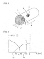
- Fig. 1 schematically shows a first example of a honeycomb body 1.
- This comprises a honeycomb structure 2 with at least partially for a fluid-permeable cavities 3, which extend in an axial direction 4 of the honeycomb body 1.
- the cavities 3 are formed by substantially smooth layers 5 and at least partially structured layers 6.
- Substantially smooth in this context means that the substantially smooth layer 5 may also have structures whose amplitude, however, smaller, preferably substantially smaller than the structures in the at least partially structured layer 6 are.
- the layers 5, 6 were stacked in a stack and this then wound around two fixed points 7.
- the honeycomb structure 2 has a sensor receptacle 8 into which a measuring sensor 9 is inserted.
- a lambda probe, a control probe, a temperature sensor and / or a gas concentration sensor for example for determining the concentration of hydrocarbons or nitrogen oxides, can be embodied as measuring sensors 9.
- a lambda probe which may also be included in a control probe.
- the sensor 9 is formed at a position which is in the range of a minimum of the hydrogen concentration in the operation of the honeycomb body 1 in an exhaust system of a motor vehicle. The location of the minimum in the axial direction 4 is determined in one of the tests described above.
- Fig. 2 shows schematically and exemplarily a profile of the concentration of hydrogen c (H 2 ) in relative units in a honeycomb body 1.
- the concentration c is projected against a coordinate x in the axial direction 4.
- the honeycomb body 1 in this example has a length L of 70 mm.
- the course of the concentration c shows a first minimum 10 at the minimum coordinate x M.
- a second minimum 11 of the hydrogen concentration c is present at the second minimum coordinate x M 2.
- the minimum coordinate x M is in the range of 30 to 40 mm behind a front side 12 of the honeycomb body 1, which in the in FIG. 2 concentration curve shown at a coordinate x of zero can be found.
- the sensor 9 is formed in the region of the minimum coordinate x M of the first minimum 10.
- Fig. 3 schematically shows a section of a longitudinal section of a honeycomb structure 2 of a honeycomb body 1.
- This honeycomb structure 2 is in monolithically formed of ceramic, for example extruded, and has a sensor receptacle 8 for receiving a not shown measuring sensor 9.
- the sensor receptacle 8 and thus also the measuring sensor 9 are in the range of the minimum coordinate x M , the region preferably extending by 10% of the length L of the honeycomb body by the minimum coordinate x M in the axial direction 4 and in the opposite direction.
- the sensor 9 or the sensor receiver 8 are therefore in a range of x M -L / 10 ⁇ x ⁇ x M + L / 10.
- the position of the measuring sensor 9 can relate both to an edge of the measuring sensor 9 and to an axis of symmetry of the measuring sensor 9. If the sensor 9 does not enter the honeycomb structure 2 at right angles to the axial direction 4 but at an angle other than 90 °, then the sensor 9 is also formed in the specified preferred ranges around the minimum coordinate x M , if only part of the sensor 9 is formed in these areas.
- the method according to the invention for positioning a measuring sensor 9 advantageously makes it possible to position a measuring sensor 9 in a honeycomb body 1 in such a way that occurring systematic errors due to an existing cross-sensitivity of the measuring sensor 9 to hydrogen are kept as low as possible. This applies in particular to lambda probes.
- the honeycomb body 1 thus comprises a measuring sensor 9, which is positioned so that it delivers particularly reliable measurement data whose systematic error is as low as possible.
Landscapes
- Engineering & Computer Science (AREA)
- Chemical & Material Sciences (AREA)
- Combustion & Propulsion (AREA)
- Mechanical Engineering (AREA)
- General Engineering & Computer Science (AREA)
- Chemical Kinetics & Catalysis (AREA)
- Analytical Chemistry (AREA)
- Exhaust Gas After Treatment (AREA)
- Catalysts (AREA)
- Measuring Oxygen Concentration In Cells (AREA)
Priority Applications (1)
| Application Number | Priority Date | Filing Date | Title |
|---|---|---|---|
| PL06706864T PL1846643T3 (pl) | 2005-02-11 | 2006-02-10 | Sposób pozycjonowania czujnika pomiarowego w elemencie o strukturze plastra miodu i odpowiedni pojazd mechaniczny |
Applications Claiming Priority (2)
| Application Number | Priority Date | Filing Date | Title |
|---|---|---|---|
| DE102005006262A DE102005006262A1 (de) | 2005-02-11 | 2005-02-11 | Verfahren zur Positionierung eines Messfühlers in einem Wabenkörper, entsprechender Wabenkörper und Kraftfahrzeug |
| PCT/EP2006/001243 WO2006084742A1 (de) | 2005-02-11 | 2006-02-10 | Verfahren zur positionierung eines messfühlers in einem wabenkörper, entsprechender wabenkörper und kraftfahrzeug |
Publications (2)
| Publication Number | Publication Date |
|---|---|
| EP1846643A1 EP1846643A1 (de) | 2007-10-24 |
| EP1846643B1 true EP1846643B1 (de) | 2012-08-15 |
Family
ID=36228659
Family Applications (1)
| Application Number | Title | Priority Date | Filing Date |
|---|---|---|---|
| EP06706864A Ceased EP1846643B1 (de) | 2005-02-11 | 2006-02-10 | Verfahren zur positionierung eines messfuehlers in einem wabenkoerper, entsprechendes kraftfahrzeug |
Country Status (9)
| Country | Link |
|---|---|
| US (1) | US7412873B2 (pl) |
| EP (1) | EP1846643B1 (pl) |
| JP (1) | JP4740262B2 (pl) |
| KR (1) | KR100893420B1 (pl) |
| CN (1) | CN101155980B (pl) |
| DE (1) | DE102005006262A1 (pl) |
| PL (1) | PL1846643T3 (pl) |
| RU (1) | RU2394993C2 (pl) |
| WO (1) | WO2006084742A1 (pl) |
Families Citing this family (9)
| Publication number | Priority date | Publication date | Assignee | Title |
|---|---|---|---|---|
| DE102007042281A1 (de) * | 2007-09-06 | 2009-03-12 | J. Eberspächer GmbH & Co. KG | Verfahren zum Anbringen einer Sonde an einer Abgasbehandlungseinrichtung |
| JP4944048B2 (ja) * | 2008-01-30 | 2012-05-30 | 日本碍子株式会社 | 挿入孔を有するハニカム構造体の強度測定方法 |
| JP5068207B2 (ja) * | 2008-03-25 | 2012-11-07 | 日本碍子株式会社 | ハニカム構造体 |
| DE102012021929A1 (de) * | 2012-11-09 | 2014-05-15 | Man Truck & Bus Ag | Verfahren und Vorrichtung zum Betrieb eines Sensors zur Bestimmung von Abgaskomponenten, insbesondere für ein Kraftfahrzeug |
| US10125659B2 (en) * | 2016-07-06 | 2018-11-13 | GM Global Technology Operations LLC | Exhaust gas treatment device having integrated gas sampling sensor |
| DE102018113985A1 (de) * | 2018-06-12 | 2019-12-12 | Dr. Ing. H.C. F. Porsche Aktiengesellschaft | Katalysatorvorrichtung zur katalytischen Reinigung eines Abgasstroms eines Verbrennungsmotors |
| CN111075541B (zh) * | 2019-12-05 | 2021-06-22 | 湖南罗佑发动机部件有限公司 | 一种催化器 |
| DE102020214867A1 (de) * | 2020-11-26 | 2022-06-02 | Vitesco Technologies GmbH | Vorrichtung zur Abgasnachbehandlung mit einem Adsorber |
| US11643959B2 (en) | 2021-02-04 | 2023-05-09 | Ford Global Technologies, Llc | Additively manufactured catalytic converter substrates |
Family Cites Families (14)
| Publication number | Priority date | Publication date | Assignee | Title |
|---|---|---|---|---|
| JPS6412018A (en) * | 1987-07-04 | 1989-01-17 | Toyota Motor Corp | Working method for air-fuel ratio sensor inserting hole in metal carrier catalyzer |
| JP2515837B2 (ja) * | 1988-02-22 | 1996-07-10 | 日本碍子株式会社 | セラミックハニカム触媒コンバ―タ |
| DE8816154U1 (de) * | 1988-12-29 | 1989-02-09 | Süddeutsche Kühlerfabrik Julius Fr. Behr GmbH & Co KG, 7000 Stuttgart | Trägerkörper für einen katalytischen Reaktor zur Abgasreinigung |
| CN1095028C (zh) * | 1997-04-09 | 2002-11-27 | 发射技术有限公司 | 监控NOx存储器的方法和设备 |
| DE19924861C1 (de) * | 1999-05-31 | 2000-10-26 | Emitec Emissionstechnologie | Keramischer Wabenkörper mit Einlagerung |
| DE10103415A1 (de) * | 2001-01-26 | 2002-10-17 | Bayerische Motoren Werke Ag | Verfahren und Vorrichtung zum Betreiben eines im Abgasweg eines Verbrennungsmotors angeordneten NOx-Sensors |
| DE10112678C2 (de) * | 2001-03-16 | 2003-04-17 | Emitec Emissionstechnologie | Verfahren zur Herstellung eines metallischen Wabenkörpers mit Aufnahme für einen Sensor |
| DE10208871A1 (de) * | 2001-03-16 | 2003-09-18 | Emitec Emissionstechnologie | Verfahren und Vorrichtung zur Herstellung eines Wabenkörpers sowie Wabenkörper |
| US7056474B2 (en) * | 2001-10-29 | 2006-06-06 | Visteon Global Technologies, Inc. | Hydrocarbon sensor and collector |
| DE10208872C1 (de) * | 2002-03-01 | 2003-08-07 | Emitec Emissionstechnologie | Verfahren zum Herstellen eines Wabenkörpers, insbesondere für einen Katalysator-Trägerkörper in Abgasreinigungsanlagen von Brennkraftmaschinen, mit einem Flanschstück zur Aufnahme für einen Messfühler und entsprechend hergestellter Wabenkörper |
| JP4320702B2 (ja) * | 2002-11-11 | 2009-08-26 | 日立金属株式会社 | 排気ガス浄化装置 |
| DE10300408A1 (de) * | 2003-01-09 | 2004-07-22 | Emitec Gesellschaft Für Emissionstechnologie Mbh | Verfahren zur Behandlung eines Fluids und Wabenkörper |
| DE10311235A1 (de) * | 2003-03-14 | 2004-10-14 | Emitec Gesellschaft Für Emissionstechnologie Mbh | Mehrsträngiges Abgassystem mit mindestens einem Messfühler, Wabenkörper mit einer Ausnehmung für mindestens einen Messfühler und Verfahren zum Betrieb eines mehrsträngigen Abgassystems |
| AT412845B (de) * | 2003-07-14 | 2005-08-25 | Alpps Fuel Cell Systems Gmbh | Abgasnachbehandlungssystem zur reduzierung der nox-emissionen von wärmekraftmaschinen mittels aus treibstoff erzeugtem reduktionsmittel |
-
2005
- 2005-02-11 DE DE102005006262A patent/DE102005006262A1/de not_active Withdrawn
-
2006
- 2006-02-10 JP JP2007554506A patent/JP4740262B2/ja not_active Expired - Fee Related
- 2006-02-10 PL PL06706864T patent/PL1846643T3/pl unknown
- 2006-02-10 WO PCT/EP2006/001243 patent/WO2006084742A1/de not_active Ceased
- 2006-02-10 EP EP06706864A patent/EP1846643B1/de not_active Ceased
- 2006-02-10 CN CN2006800116618A patent/CN101155980B/zh not_active Expired - Fee Related
- 2006-02-10 RU RU2007133725/06A patent/RU2394993C2/ru not_active IP Right Cessation
- 2006-02-10 KR KR1020077020710A patent/KR100893420B1/ko not_active Expired - Fee Related
-
2007
- 2007-08-13 US US11/837,578 patent/US7412873B2/en not_active Expired - Lifetime
Also Published As
| Publication number | Publication date |
|---|---|
| WO2006084742A1 (de) | 2006-08-17 |
| KR20070103485A (ko) | 2007-10-23 |
| CN101155980B (zh) | 2011-03-09 |
| US20080011054A1 (en) | 2008-01-17 |
| JP2008530425A (ja) | 2008-08-07 |
| KR100893420B1 (ko) | 2009-04-17 |
| US7412873B2 (en) | 2008-08-19 |
| RU2007133725A (ru) | 2009-04-10 |
| CN101155980A (zh) | 2008-04-02 |
| EP1846643A1 (de) | 2007-10-24 |
| DE102005006262A1 (de) | 2006-08-24 |
| JP4740262B2 (ja) | 2011-08-03 |
| RU2394993C2 (ru) | 2010-07-20 |
| PL1846643T3 (pl) | 2013-01-31 |
Similar Documents
| Publication | Publication Date | Title |
|---|---|---|
| DE102020127384B4 (de) | Probenentnahmevorrichtung für einen abgassensor | |
| DE69901992T2 (de) | Längenverhältnis der Einlass- und Auslasssammelkammer eines katalytischen Konverters | |
| DE102018001405A1 (de) | Abgasvorrichtung für einen Motor und Verfahren zum Ausbringen von Abgas einer Brennkraftmaschine | |
| US7412873B2 (en) | Method for positioning a measuring sensor in a honeycomb body, corresponding honeycomb body, and motor vehicle | |
| DE60108013T2 (de) | Verfahren und Vorrichtung zur direkten Überwachung des Wirkungsgrads eines Konditionierungskatalysators | |
| EP1944481B1 (de) | Vorrichtung zur Abschätzung des Beladungszustandes eines NOx-Speicherkatalysators | |
| EP3655634B1 (de) | Abgasanlage für eine brennkraftmaschine | |
| DE102018001426B4 (de) | Abgasvorrichtung für einen Motor und Verfahren zum Detektieren eines Druckabfalls eines Partikelfilters | |
| EP1680581B1 (de) | Beschichteter wabenkörper mit messfühler | |
| DE4128997A1 (de) | Verfahren und vorrichtung zur regelung und pruefung | |
| DE102020004775A1 (de) | Katalysatorabbau-diagnosesystem und katalysatorabbau-diagnoseverfahren | |
| EP4092256B1 (de) | Abgasanlage einer verbrennungskraftmaschine | |
| EP1604100B1 (de) | Mehrsträngiges abgassystem mit mindestens einem messfühler, wabenkörper mit einer ausnehmung für mindestens ei nen messfühler und verfahren zum betrieb eines mehrsträ ngigen abgassystems | |
| DE10300408A1 (de) | Verfahren zur Behandlung eines Fluids und Wabenkörper | |
| WO2005056987A2 (de) | Wabenkörper mit mindestens einem platzsparenden messfühler, sowie entsprechende lambdasonde | |
| EP4127658B1 (de) | Optischer sensor zur detektion eines gases, seine verwendung sowie fortbewegungsmittel mit einem solchen sensor | |
| DE102018001458B4 (de) | Abgasvorrichtung für einen Motor und Verfahren zum Ausbilden derselben | |
| DE102004017883B4 (de) | Abgasanlage für eine Brennkraftmaschine eines Fahrzeuges, insbesondere eines Kraftfahrzeuges | |
| DE10032571A1 (de) | Verfahren zur Zustandserfassung eines Katalysatorsystems | |
| DE102019007211A1 (de) | Verfahren zur Partikelmessung im Abgas einer Verbrennungskraftmaschine und Partikelmessvorrichtung | |
| DE102020214867A1 (de) | Vorrichtung zur Abgasnachbehandlung mit einem Adsorber | |
| EP1452860A1 (de) | Sensorelement und Verfahren zur Bestimmung von Ammoniak | |
| DE102017222253A1 (de) | Verfahren zum Betrieb einer Abgasnachbehandlungsvorrichtung eines Kraftfahrzeugs | |
| DE102017113691A1 (de) | Abgasnachbehandlungsvorrichtung und Verfahren zur Abgasnachbehandlung eines Verbrennungsmotors | |
| DE102021203096A1 (de) | Abgasnachbehandlungssystem |
Legal Events
| Date | Code | Title | Description |
|---|---|---|---|
| PUAI | Public reference made under article 153(3) epc to a published international application that has entered the european phase |
Free format text: ORIGINAL CODE: 0009012 |
|
| 17P | Request for examination filed |
Effective date: 20070717 |
|
| AK | Designated contracting states |
Kind code of ref document: A1 Designated state(s): DE ES FR GB IT PL |
|
| RIN1 | Information on inventor provided before grant (corrected) |
Inventor name: BRUECK, ROLF Inventor name: ALTHOEFER, KAIT Inventor name: HIRTH, PETER |
|
| DAX | Request for extension of the european patent (deleted) | ||
| RBV | Designated contracting states (corrected) |
Designated state(s): DE ES FR GB IT PL |
|
| 17Q | First examination report despatched |
Effective date: 20091214 |
|
| REG | Reference to a national code |
Ref country code: DE Ref legal event code: R079 Ref document number: 502006011851 Country of ref document: DE Free format text: PREVIOUS MAIN CLASS: F01N0011000000 Ipc: F01N0013000000 |
|
| GRAP | Despatch of communication of intention to grant a patent |
Free format text: ORIGINAL CODE: EPIDOSNIGR1 |
|
| RIC1 | Information provided on ipc code assigned before grant |
Ipc: F01N 11/00 20060101ALI20120131BHEP Ipc: F01N 13/00 20100101AFI20120131BHEP |
|
| RTI1 | Title (correction) |
Free format text: METHOD FOR POSITIONING A SENSOR IN A HONEYCOMB ELEMENT, CORRESPONDING MOTOR VEHICLE |
|
| GRAS | Grant fee paid |
Free format text: ORIGINAL CODE: EPIDOSNIGR3 |
|
| GRAA | (expected) grant |
Free format text: ORIGINAL CODE: 0009210 |
|
| AK | Designated contracting states |
Kind code of ref document: B1 Designated state(s): DE ES FR GB IT PL |
|
| REG | Reference to a national code |
Ref country code: GB Ref legal event code: FG4D Free format text: NOT ENGLISH |
|
| REG | Reference to a national code |
Ref country code: DE Ref legal event code: R081 Ref document number: 502006011851 Country of ref document: DE Owner name: CONTINENTAL AUTOMOTIVE GMBH, DE Free format text: FORMER OWNER: EMITEC GESELLSCHAFT FUER EMISSIONSTECHNOLOGIE MBH, 53797 LOHMAR, DE |
|
| REG | Reference to a national code |
Ref country code: DE Ref legal event code: R096 Ref document number: 502006011851 Country of ref document: DE Effective date: 20121018 |
|
| REG | Reference to a national code |
Ref country code: PL Ref legal event code: T3 |
|
| PG25 | Lapsed in a contracting state [announced via postgrant information from national office to epo] |
Ref country code: ES Free format text: LAPSE BECAUSE OF FAILURE TO SUBMIT A TRANSLATION OF THE DESCRIPTION OR TO PAY THE FEE WITHIN THE PRESCRIBED TIME-LIMIT Effective date: 20121126 |
|
| PLBE | No opposition filed within time limit |
Free format text: ORIGINAL CODE: 0009261 |
|
| STAA | Information on the status of an ep patent application or granted ep patent |
Free format text: STATUS: NO OPPOSITION FILED WITHIN TIME LIMIT |
|
| 26N | No opposition filed |
Effective date: 20130516 |
|
| REG | Reference to a national code |
Ref country code: DE Ref legal event code: R097 Ref document number: 502006011851 Country of ref document: DE Effective date: 20130516 |
|
| REG | Reference to a national code |
Ref country code: FR Ref legal event code: PLFP Year of fee payment: 11 |
|
| REG | Reference to a national code |
Ref country code: DE Ref legal event code: R081 Ref document number: 502006011851 Country of ref document: DE Owner name: VITESCO TECHNOLOGIES GMBH, DE Free format text: FORMER OWNER: EMITEC GESELLSCHAFT FUER EMISSIONSTECHNOLOGIE MBH, 53797 LOHMAR, DE Ref country code: DE Ref legal event code: R082 Ref document number: 502006011851 Country of ref document: DE Ref country code: DE Ref legal event code: R081 Ref document number: 502006011851 Country of ref document: DE Owner name: CONTINENTAL AUTOMOTIVE GMBH, DE Free format text: FORMER OWNER: EMITEC GESELLSCHAFT FUER EMISSIONSTECHNOLOGIE MBH, 53797 LOHMAR, DE |
|
| REG | Reference to a national code |
Ref country code: GB Ref legal event code: 732E Free format text: REGISTERED BETWEEN 20160331 AND 20160406 |
|
| REG | Reference to a national code |
Ref country code: FR Ref legal event code: PLFP Year of fee payment: 12 |
|
| PGFP | Annual fee paid to national office [announced via postgrant information from national office to epo] |
Ref country code: GB Payment date: 20170216 Year of fee payment: 12 |
|
| REG | Reference to a national code |
Ref country code: FR Ref legal event code: PLFP Year of fee payment: 13 |
|
| PGFP | Annual fee paid to national office [announced via postgrant information from national office to epo] |
Ref country code: PL Payment date: 20180206 Year of fee payment: 13 |
|
| GBPC | Gb: european patent ceased through non-payment of renewal fee |
Effective date: 20180210 |
|
| PG25 | Lapsed in a contracting state [announced via postgrant information from national office to epo] |
Ref country code: GB Free format text: LAPSE BECAUSE OF NON-PAYMENT OF DUE FEES Effective date: 20180210 |
|
| REG | Reference to a national code |
Ref country code: DE Ref legal event code: R081 Ref document number: 502006011851 Country of ref document: DE Owner name: EMITEC TECHNOLOGIES GMBH, DE Free format text: FORMER OWNER: CONTINENTAL AUTOMOTIVE GMBH, 30165 HANNOVER, DE Ref country code: DE Ref legal event code: R081 Ref document number: 502006011851 Country of ref document: DE Owner name: VITESCO TECHNOLOGIES GMBH, DE Free format text: FORMER OWNER: CONTINENTAL AUTOMOTIVE GMBH, 30165 HANNOVER, DE |
|
| PG25 | Lapsed in a contracting state [announced via postgrant information from national office to epo] |
Ref country code: PL Free format text: LAPSE BECAUSE OF NON-PAYMENT OF DUE FEES Effective date: 20190210 |
|
| REG | Reference to a national code |
Ref country code: DE Ref legal event code: R081 Ref document number: 502006011851 Country of ref document: DE Owner name: EMITEC TECHNOLOGIES GMBH, DE Free format text: FORMER OWNER: VITESCO TECHNOLOGIES GMBH, 30165 HANNOVER, DE Ref country code: DE Ref legal event code: R081 Ref document number: 502006011851 Country of ref document: DE Owner name: VITESCO TECHNOLOGIES GMBH, DE Free format text: FORMER OWNER: VITESCO TECHNOLOGIES GMBH, 30165 HANNOVER, DE |
|
| REG | Reference to a national code |
Ref country code: DE Ref legal event code: R084 Ref document number: 502006011851 Country of ref document: DE |
|
| PGFP | Annual fee paid to national office [announced via postgrant information from national office to epo] |
Ref country code: IT Payment date: 20220218 Year of fee payment: 17 Ref country code: FR Payment date: 20220216 Year of fee payment: 17 |
|
| P01 | Opt-out of the competence of the unified patent court (upc) registered |
Effective date: 20230830 |
|
| REG | Reference to a national code |
Ref country code: DE Ref legal event code: R081 Ref document number: 502006011851 Country of ref document: DE Owner name: EMITEC TECHNOLOGIES GMBH, DE Free format text: FORMER OWNER: VITESCO TECHNOLOGIES GMBH, 93055 REGENSBURG, DE Ref country code: DE Ref legal event code: R082 Ref document number: 502006011851 Country of ref document: DE Representative=s name: KARO IP PATENTANWAELTE KAHLHOEFER ROESSLER KRE, DE Ref country code: DE Ref legal event code: R082 Ref document number: 502006011851 Country of ref document: DE Representative=s name: KARO IP PATENTANWAELTE PARTG MBB, DE |
|
| PG25 | Lapsed in a contracting state [announced via postgrant information from national office to epo] |
Ref country code: IT Free format text: LAPSE BECAUSE OF NON-PAYMENT OF DUE FEES Effective date: 20230210 Ref country code: FR Free format text: LAPSE BECAUSE OF NON-PAYMENT OF DUE FEES Effective date: 20230228 |
|
| PGFP | Annual fee paid to national office [announced via postgrant information from national office to epo] |
Ref country code: DE Payment date: 20240228 Year of fee payment: 19 |
|
| REG | Reference to a national code |
Ref country code: DE Ref legal event code: R119 Ref document number: 502006011851 Country of ref document: DE |
|
| PG25 | Lapsed in a contracting state [announced via postgrant information from national office to epo] |
Ref country code: DE Free format text: LAPSE BECAUSE OF NON-PAYMENT OF DUE FEES Effective date: 20250902 |