EP1846681B2 - Vorrichtung zur steuerung der schaltbewegung eines ventils - Google Patents
Vorrichtung zur steuerung der schaltbewegung eines ventils Download PDFInfo
- Publication number
- EP1846681B2 EP1846681B2 EP06706239.8A EP06706239A EP1846681B2 EP 1846681 B2 EP1846681 B2 EP 1846681B2 EP 06706239 A EP06706239 A EP 06706239A EP 1846681 B2 EP1846681 B2 EP 1846681B2
- Authority
- EP
- European Patent Office
- Prior art keywords
- control unit
- valve
- interface
- internal control
- internal
- Prior art date
- Legal status (The legal status is an assumption and is not a legal conclusion. Google has not performed a legal analysis and makes no representation as to the accuracy of the status listed.)
- Expired - Lifetime
Links
Images
Classifications
-
- F—MECHANICAL ENGINEERING; LIGHTING; HEATING; WEAPONS; BLASTING
- F16—ENGINEERING ELEMENTS AND UNITS; GENERAL MEASURES FOR PRODUCING AND MAINTAINING EFFECTIVE FUNCTIONING OF MACHINES OR INSTALLATIONS; THERMAL INSULATION IN GENERAL
- F16K—VALVES; TAPS; COCKS; ACTUATING-FLOATS; DEVICES FOR VENTING OR AERATING
- F16K37/00—Special means in or on valves or other cut-off apparatus for indicating or recording operation thereof, or for enabling an alarm to be given
- F16K37/0075—For recording or indicating the functioning of a valve in combination with test equipment
- F16K37/0083—For recording or indicating the functioning of a valve in combination with test equipment by measuring valve parameters
-
- F—MECHANICAL ENGINEERING; LIGHTING; HEATING; WEAPONS; BLASTING
- F16—ENGINEERING ELEMENTS AND UNITS; GENERAL MEASURES FOR PRODUCING AND MAINTAINING EFFECTIVE FUNCTIONING OF MACHINES OR INSTALLATIONS; THERMAL INSULATION IN GENERAL
- F16K—VALVES; TAPS; COCKS; ACTUATING-FLOATS; DEVICES FOR VENTING OR AERATING
- F16K37/00—Special means in or on valves or other cut-off apparatus for indicating or recording operation thereof, or for enabling an alarm to be given
- F16K37/0075—For recording or indicating the functioning of a valve in combination with test equipment
- F16K37/0091—For recording or indicating the functioning of a valve in combination with test equipment by measuring fluid parameters
Definitions
- the invention relates to a device for controlling the switching movement of a valve, wherein the control device is modularly structured and the valve has at least one valve rod carrying a closing element and moved in a translational or rotational manner, the valve rod(s) is/are moved into two end positions, a closed position and an open position, by means of a pressure-medium-loaded valve drive, if necessary at least one valve rod is moved into an intermediate position positioned between these end positions and forming a partially open position of the associated closing element, the control device has means for controlling the pressure medium for the valve drive and a position sensor which detects at least the end positions and possibly the intermediate position of the valve rod in relation to a fixed reference system and provides current position reports in this regard, and the control device has a modular, internal control unit which on the one hand exchanges data with an external control unit in the vicinity of the valve and on the other hand controls the means for controlling the pressure medium.
- a device for controlling the switching movement of a valve in which the adjustment movement of the valve rod is continuously monitored by a position measuring system and fixed valve positions, such as the fully open position or the closed position, are determined, is known from WO 02/093 058 A1
- the device has means for controlling the pressure medium for a valve drive, furthermore a position indicator or transmitter which is connected to the valve rod and which represents the current position of the valve rod, which reflects the valve rod movement. continuously recorded in relation to a specified reference system and provides current position reports in this regard, means for continuously storing the current position reports and, in addition, means for calculating and comparing data from specified data and/or data recorded during the valve movements.
- the position indicator is designed as a non-contact position display device and all the means required to control the valve are arranged in a control head which is provided on the side of the valve drive facing away from the valve housing.
- simplified devices for controlling the switching movement of a valve are known in which continuous measurement of the valve rod's path is dispensed with and only discrete, fixed valve positions are recorded on the respective valve in question via position sensors and fed back to an internal and/or external control system of the valve.
- the position sensors record the respective position of the valve rod either by contact or without contact.
- Magnetic position sensors are known as contact-free position sensors, for example, and generate a switching signal when, for example, a permanent magnet attached to the valve rod comes close to the position sensor detecting a magnetic field.
- control devices are basically constructed in such a way that an internal control unit is provided in a control head arranged on the valve drive, which on the one hand exchanges data with an external control unit, for example a programmable logic controller (PLC), and on the other hand controls means for controlling a pressure medium, so-called pilot valves, which are provided for supplying the valve drive with this pressure medium.
- PLC programmable logic controller
- the internal control unit is designed in such a way in terms of voltage that the pilot valves can be controlled with the control voltage on which it is based, and on the other hand also communicates with the external control unit (PLC).
- PLC programmable logic controller
- the internal control unit is designed in such a way in terms of voltage that the pilot valves can be controlled with the control voltage on which it is based, and on the other hand also communicates with the external control unit (PLC).
- PLC programmable logic controller
- an operating voltage of 24 volts direct current (24 VDC) has become widely established.
- the external control units In Germany, but primarily abroad, the external control units (PLCs) are also operated with alternating voltages in the range of 20 to 130 volts (20 - 130 VAC). If the pilot valves are also operated with a voltage other than 24 VDC, then solutions specifically adapted to these voltage conditions are necessary with regard to the internal control unit so that the latter can communicate with the external control unit (PLCs) on the one hand and the pilot valves on the other.
- the internal control unit communicates with the external control unit (PLC) via a two-wire BUS cable via a so-called AS-Interface module, i.e. via binary signals.
- PLC external control unit
- An electromagnetic drive with an electrical adjustment module which actuates a valve for controlling fluids.
- the adjustment module used in each case connects the internal electrical control unit of the electromagnetic drive with an external electrical supply system, which can be available in a wide variety of forms.
- the respective adaptation module in particular adapts the electromagnetic drive to the respective contact system of the external electrical supply system.
- the adaptation module can also provide means for converting and adapting external electrical voltages (direct and alternating voltages) to the internally required voltage of the electromagnetic drive.
- the closing element of the valve engages with a shaft-shaped end in the electrical coil system of the electromagnetic drive and is thereby actuated directly. Pilot valves for controlling a pressure medium are therefore not required.
- the known electromagnetic drive does not have a position sensor in conjunction with the valve for detecting end or intermediate positions of the valve.
- the inventive basic idea is to operate all possible equipment variants of the control device, which are given by different operating voltages and/or data protocols, with a standardized internal control unit, a so-called base unit, which has a standardized operating voltage.
- This internal control unit then also uses this standardized operating voltage to control the means designed as pilot valves for controlling the pressure medium.
- the internal control unit can be used together with a pilot valve or together with up to three pilot valves, regardless of the respective operating voltage of the external control unit.
- a second inventive basic idea is to place the adaptation to the respective operating voltage of the external control unit (for example PLC) or to the data communication with it in an adaptation module that is connected to the internal control unit via an internal interface and to the external control unit via an external interface.
- the adaptation module is designed in such a way that the respective signal structure of the control unit and the adaptation module at the internal interface are the same.
- the internal control unit is supplied with voltage via the adaptation module, with the adaptation module adapting to the respective operating voltage of the external control unit.
- the control device according to the invention is not only applicable to lift valves in which a single, translationally moved closing element works against an associated seat surface, but it is also applicable to so-called double seat valves with two independently operable closing elements which enclose a leakage cavity between them in both the closed and open positions of the double seat valve, which is connected to the environment of the double seat valve via at least one connecting path.
- Each closing element is connected to an associated valve rod and at least one of these valve rods, preferably that of the independently operable closing element, is monitored with regard to its respective position in connection with the associated closing element (closed position, open position, intermediate position) by the position sensor of the control device according to the invention.
- control device can also be used for valves in which the closing element carries out a rotary opening and closing movement (for example, disc valves).
- the rotary movement of the valve rod associated with the respective closing element can be directly controlled and monitored by the control device according to the invention.
- the rotary movement can also be indirectly controlled and monitored by this. monitored by controlling and monitoring an associated valve drive that generates the rotary valve rod movement.
- the rotary movement of the closing element and the associated valve rod is usually generated via a translatory, back-and-forth movement of a piston pressurized with pressure medium, whereby it is easier to control and monitor this translatory movement than a rotary one.
- An advantageous embodiment of the control device provides that the internal control unit operates with a standardized operating voltage of 24 VDC (direct voltage). With this standardized operating voltage of 24 VDC, the standard applications can be covered and the internal control unit can exchange data directly with the external control unit via the internal interface.
- a first adaptation module is designed as a so-called AC interface module, which converts the signals and the signal level of the internal control unit operating with the standardized operating voltage to a predetermined, arbitrary operating voltage in the range of 20 to 130 VAC (alternating voltage) and makes them available at an external interface via which it is connected to the external control unit, and also carries out a corresponding conversion in the opposite direction.
- the standardized internal control unit can thus communicate via the first adaptation module with any external control unit that operates in the range of 20 to 130 VAC.
- the necessary adaptation measures are placed in the modularly structured first adaptation module and thus have no influence on the design and layout of the standardized internal control unit.
- a second adaptation module a so-called AS-Interface module, which converts the signals and the signal level of the internal control unit working with the standardized operating voltage to the corresponding signals and the signal level of an AS-Interface BUS data transmission system working with a two-wire BUS line and at an external interface via which it is connected to the external control unit connected, and also carries out a corresponding implementation in the opposite direction.
- AS-Interface module converts the signals and the signal level of the internal control unit working with the standardized operating voltage to the corresponding signals and the signal level of an AS-Interface BUS data transmission system working with a two-wire BUS line and at an external interface via which it is connected to the external control unit connected, and also carries out a corresponding implementation in the opposite direction.
- inventive basic ideas can also be transferred to other BUS solutions and other AC or DC voltages with which the external control units may be operated, whereby in any case the standardized internal control unit described above can be used unchanged.
- the different modular configurations of the control device according to the invention can be implemented particularly easily if, as is further proposed, the external interface and the internal interface are each designed as a terminal block.
- the second terminal block is advantageously designed as a male connector, and according to a further proposal, the contact pins of the male connector are designed on the adaptation module.
- the contact pins are each attached to an associated screw terminal on the internal control unit, then this contact alone creates a secure connection between the adaptation module and the internal control unit, which then only need to be connected to one another at a suitable location via a single positive connection, for example a simple screw connection, in order to ensure an absolutely secure connection between these two modular components.
- the AC interface module is used to adapt signals for the exchange of control signals to electronic modules in the internal control unit that work with pressurized (preferably pneumatic) drives.
- the internal control unit consists of an electronic unit based on a standardized operating voltage, for example a direct voltage of 24 VDC, which receives control signals and provides signals for monitoring purposes.
- the internal control unit requires the standardized operating voltage, in this case a direct voltage of 24 VDC.
- the above-mentioned inventive concept is implemented by coupling the AC interface module, the first adaptation module, to the internal control unit, which is also modular.
- any alternating voltage in the range of 20 to 130 volts is converted to the signal level of the internal control unit (base unit) operating at 24 VDC in order to ensure control of the 24 VDC pilot valves.
- the feedback signals for the discrete valve positions (closed position, fully open position and, if applicable, intermediate position(s)), which reach the AC interface module via the internal control unit, are then converted to the input level of this module.
- the user can thus control pilot valves with an alternating voltage signal and receives the same AC signal level (alternating voltage signal level) back as feedback.
- the AS-Interface module described below serves as an optional extension module for use in devices for controlling the switching movement of a valve, whereby the internal control unit (base unit) is in turn standardized and works with a standardized operating voltage, preferably a voltage of 24 VDC (direct current).
- the AS-Interface module is connected to the AS-Interface master or a gateway via the so-called AS-Interface BUS.
- a two-wire BUS cable is used here, which simultaneously provides the operating voltage for the AS-Interface module and is contacted via two terminals on the AS-Interface module.
- the AS-Interface module is connected to the internal control unit in the same way as described above and in connection with the AC-Interface module, namely via the internal interface.
- connection terminals of the internal control unit are connected to corresponding cables for signal transmission to the external control unit, via which 24 VDC binary signals are then transmitted to this external control unit (PLC).
- PLC external control unit
- the external control unit is upgraded with an AS-Interface module, all that is needed is to remove the cables to the external control unit (PLC) and connect the corresponding AS-Interface module at the same point.
- PLC external control unit
- the standardized internal control unit only has one interface for signals that either go directly to the external control unit (PLC) or, if the AS-Interface module is connected, that these signals are converted to the AS-Interface data protocol in the AS-Interface module, so that communication with an AS-Interface master is then possible via the data cable.
- the I/O interface (input/output interface) of the AS-Interface module is electrically connected to the standardized internal control unit via a male connector. Digital output signals from the AS-Interface module are transmitted to the internal control unit via this interface, as are digital output signals from the internal control unit to the AS-Interface module. In addition, the AS-Interface module supplies the internal control unit with operating voltage.
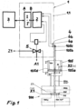
- a control device 1 comprises in a housing unit 1.1 an internal control unit 2, a position sensor 4 consisting of a first and a second position sensor 4a, 4b and a means 5 (pilot valve) for controlling a pressure medium D.
- the internal control unit 2 communicates directly with an external control unit 3 (e.g. a programmable logic controller (PLC))
- PLC programmable logic controller
- the configuration just described is state of the art and serves to control the switching movement of a valve 100, which in the illustrated embodiment is designed as a lift valve.
- the latter accommodates a closing element 101 between a first and a second valve housing 100a or 100b.
- valve rod 101a which is connected to an actuator 105b, an upwardly extended valve rod, to which a permanent magnet 105c is attached.
- the closing member 101 interacts with a seat surface 102 via a seat seal 106, it controls a connecting bore (not designated) between the first and second valve housings 100a and 100b, respectively, and it has a first fixed valve position, the shown closed position SS, and a second fixed valve position, the open position OS. Between these two fixed valve positions, the two end positions, a so-called full stroke H of the closing member 101 is formed.
- the closing member 101 can also be moved to a partially open position, an intermediate position ZS, if necessary.
- control device 1 in addition to the aforementioned valve with a single closing element 101, a so-called normal valve, the control device 1 according to the invention can also be used on a so-called double seat valve, which has two independently operable closing elements, the closing element 101 and a second closing element 101*, which, via associated valve rods, the valve rod 101 a for the Closing member 101 and a second valve rod 101a* for the second closing member 101*.
- a piston 105a connected to the independently driven closing member 101 via the valve rod 101a in each valve drive 105 is pressurized with the pressure medium D via a first pressure medium connection 103 either from outside the valve drive 105 or via a bore 105d from inside the same, wherein this bore 105d opens into the interior of the housing unit 1.1 via connecting paths not shown and is connected there via the pilot valve 5 to a pressure medium supply Z1.
- the defined first end position of the closing element 101 in its closed position SS, the first fixed valve position, is brought about by its metallic contact on the associated seat surface 102.
- the latter forms a fixed first position limit X1 (first metallic stop).
- the open position OS of the valve plate 101, the second end position and thus the second fixed valve position is realized, for example, as shown schematically, by the piston 105a contacting a second position limit X2 in the valve drive 105 (second metallic stop).
- the two end positions, the shown closed position SS and the fully open position OS, are detected by the first position sensor 4a and the second position sensor 4b, respectively, and reported back to the internal control unit 2.
- the latter controls the pilot valve 5, via which the pressure medium D passes from the pressure medium supply Z1 into a space within the valve drive 105 below the piston 105a.
- it is a so-called spring-closing valve drive 105, which displaces the pressure medium D from the space below the piston 105a via the pilot valve 5 and a pressure medium discharge A1 when the pilot valve 5 is not controlled.
- valve disk 101 in the non-controlled state is held by an additional force on its seat surface 102.
- the piston 105a on the rear side is pressurized with pressure medium D via a second pressure medium connection 104.
- the second pressure medium connection 104 is controlled via a so-called NOT element (not shown), which is controlled when required and whenever the piston 105a is not controlled via the first pressure medium connection 103.
- the NOT element (not shown) is also controlled by the internal control unit 2.
- the control device 1 described above which represents the state of the art, requires a specially designed internal control unit 2 if the latter operates with a different operating voltage than the external control unit 3 with which it is connected and exchanges data. Further appropriate adaptation measures are required if the pilot valve 5 has an operating voltage that deviates from the 24 VDC standard.
- the adaptation measures are not placed in the internal control unit 2, but either in a first adaptation module I according to the invention, a so-called AC interface module, or alternatively, if a data bus system is provided, in a second adaptation module I* described further, a so-called AS interface module.
- the AC or AS interface module I or I* is connected on the one hand via an internal interface B, a second terminal block, to the internal control unit 2 and on the other hand via an external interface A to the external control unit 3 (see also Figures 2a, 2b and 3a, 3b ).
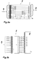
- the housing for the AC interface module I (first adaptation module) ( Figure 2a ) preferably has a substantially cuboidal design, which has the smallest possible dimensions and completely encloses the electronics. A on the former with a hole, so that a positive connection can be made between these two components, for example by screwing.
- the external cabling (connection from the external control unit 3 (e.g. a PLC)) to the AC interface module I is placed on the latter on the first terminal block A.
- the connection from the AC interface module I to the internal control unit 2 is made via the second terminal block B, which is designed as a male connector, whereby contact pins Bi of the male connector B are inserted directly into the terminals on the internal control unit 2 and screwed in.
- the first terminal block A and the second terminal block B each have terminals 11 to 20, the respective assignment or use of which can be seen from Figure 2b can be seen.
- Terminals 11 to 13 are assigned to the inputs e 1 , e 2 and e 3 for the feedback of the fixed valve positions (closed position SS, open position OS and, if applicable, intermediate position ZS).
- Terminals 14 to 16 are for the pilot valves Y1, Y2 and Y3 (see Figure 3b ) leading outputs a 1 , a 2 and a 3 are provided.
- the electrical parameters for the second terminal block B are as follows:
- the electrical parameters for the first terminal block A are as follows:
- AS-Interface Module I* second adaptation module
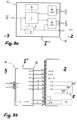
- the structure of the AS-Interface Module I* (second adaptation module) is basically Figure 3a It essentially has an address memory 6, an AS-i chip 7, a voltage converter 8, an input level 9 (24 VDC) and an output level 10 (24 VDC).
- the AS-Interface module I* is connected to the internal control unit 2 on the right side (internal interface B) and to the external control unit 3 on the left side (external interface A) via the so-called BUS connections using a two-wire BUS cable (+AS-i and -AS-i).
- the AS-Interface module I* has three inputs e 1 , e 2 and e 3 for feedback from the positions of the valve (terminals 11 to 13) and that it is connected to the internal control unit 2 (terminals 14 to 16) via three outputs a 1 , a 2 and a 3 for the pilot valves 5 (Y1, Y2, Y3).
- the remaining terminal assignment of the internal interface B is Figure 2b visible.
Landscapes
- Engineering & Computer Science (AREA)
- General Engineering & Computer Science (AREA)
- Mechanical Engineering (AREA)
- Magnetically Actuated Valves (AREA)
- Fluid-Driven Valves (AREA)
- Electrically Driven Valve-Operating Means (AREA)
- High-Tension Arc-Extinguishing Switches Without Spraying Means (AREA)
- Indication Of The Valve Opening Or Closing Status (AREA)
Description
- Die Erfindung betrifft eine Vorrichtung zur Steuerung der Schaltbewegung eines Ventils, wobei die Steuervorrichtung modular strukturiert ist und das Ventil wenigstens eine ein Schließglied tragende, translatorisch oder rotativ bewegte Ventilstange aufweist, die Ventilstange(n) mittels eines druckmittelbeaufschlagten Ventilantriebes in zwei Endstellungen, eine Schließ- und eine Offenstellung, verbracht wird/werden, erforderlichenfalls wenigstens eine Ventilstange in eine zwischen diesen Endstellungen positionierte, eine Teiloffenstellung des zugeordneten Schließgliedes bildende Zwischenstellung verbracht wird, die Steuervorrichtung Mittel zur Steuerung des Druckmittels für den Ventilantrieb sowie einen Stellungsgeber aufweist, der wenigstens die Endstellungen und ggf. die Zwischenstellung der Ventilstange in Bezug auf ein festgelegtes Bezugssystem erfasst und diesbezügliche aktuelle Stellungsmeldungen liefert, und die Steuervorrichtung eine modulare, interne Steuereinheit aufweist, die einerseits mit einer externen Steuereinheit im Umfeld des Ventils im Datenaustausch steht und andererseits die Mittel zur Steuerung des Druckmittels ansteuert.
- Eine Vorrichtung zur Steuerung der Schaltbewegung eines Ventils, bei der die Verstellbewegung der Ventilstange durch ein Wegmess-System laufend überwacht wird und dabei feste Ventilstellungen, wie beispielsweise die volle Offenstellung oder die Schließstellung, ermittelt werden, ist aus der
WO 02/093 058 A1 - Weiterhin sind gegenüber dem vorgenannten Stand der Technik vereinfachte Vorrichtungen zur Steuerung der Schaltbewegung eines Ventils bekannt, bei denen auf eine kontinuierliche Wegmessung der Ventilstange verzichtet wird und am in Frage kommenden jeweiligen Ventil lediglich diskrete, feste Ventilstellungen über Stellungsgeber erfasst und an eine interne und/oder externe Steuerung des Ventils rückgemeldet werden. Dabei erfassen die Stellungsgeber die jeweilige Stellung der Ventilstange entweder berührend oder berührungsfrei. Als berührungsfrei arbeitende Stellungsgeber sind beispielsweise magnetisch arbeitende bekannt, die ein Schaltsignal generieren, wenn beispielsweise ein an der Ventilstange befestigter Permanentmagnet in die Nähe des ein magnetisches Feld detektierenden Stellungsgebers gelangt.
- Die vorgenannten Vorrichtungen zur Steuerung der Schaltbewegung eines Ventils, nachfolgend kurz Steuervorrichtungen genannt, sind grundsätzlich derart aufgebaut, dass in einem am Ventilantrieb angeordneten Steuerkopf eine interne Steuereinheit vorgesehen ist, die einerseits mit einer externen Steuereinheit, beispielsweise einer speicherprogrammierbaren Steuerung (SPS), im Datenaustausch steht und andererseits Mittel zur Steuerung eines Druckmittels, sog. Pilotventile, ansteuert, die für die Versorgung des Ventilantriebs mit diesem Druckmittel vorgesehen sind. Dabei ist die interne Steuereinheit derart spannungsmäßig ausgelegt, dass mit der ihr zugrundeliegenden Steuerspannung einerseits die Pilotventile ansteuerbar sind und andererseits auch eine Kommunikation mit der externen Steuereinheit (SPS) möglich ist. In Deutschland hat sich beispielsweise eine Betriebsspannung von 24 Volt Gleichspannung (24 VDC) weitestgehend etabliert.
- Die externen Steuereinheiten (SPS) werden in Deutschland, vornehmlich aber im Ausland, auch mit Wechselspannungen im Bereich von 20 bis 130 Volt (20 - 130 VAC) betrieben. Werden dann auch noch die Pilotventile mit einer anderen Spannung als 24 VDC betrieben, dann sind speziell an diese Spannungsverhältnisse angepasste Lösungen mit Blick auf die interne Steuereinheit notwendig, damit letztere in Richtung der externen Steuereinheit (SPS) einerseits und der Pilotventile andererseits kommunizieren kann.
- Daraus ergibt sich bislang eine Vielfalt unterschiedlicher interner Steuereinheiten als Folge der vorgenannten unterschiedlichen Betriebsspannungen und auch als Folge des gegebenen unterschiedlichen Datenaustauschs. Ein derartiger Zustand ist unbefriedigend, da ein relativ großer Aufwand zur jeweiligen Aus- und/oder Umrüstung der Ventilsteuerungen notwendig ist. Eine Vorfertigung vielfältiger Ausstattungsvarianten bedeutet einen hohen Lagerbestand, falls man auf alle vorgenannten Varianten vorbereitet sein will. Eine Reduzierung dieses Lagerbestandes führt zur unwirtschaftlichen Fertigung kleiner Losgrößen. Weiterhin bedeutet eine derartige Vielfalt an Ausstattungsvarianten der Steuervorrichtung, dass ein entsprechender Entwicklungsaufwand getrieben werden muss, dass die Lagerhaltung hinsichtlich der Lagerverwaltung (Sachnummern) aufwändig ist und dass jede Ausstattungsvariante einer kostspieligen Zulassungsprüfung zu unterziehen ist.
- Die Zahl der vorgenannte Ausstattungsvarianten wird noch erhöht, wenn, wie dies in vielen Fällen praktiziert wird, die interne Steuereinheit mittels einer zweiadrigen BUS-Leitung über einen sog. AS-Interface Modul, d.h. über Binär-Signale mit der externen Steuereinheit (SPS) kommuniziert.
- In der
US 4 683 454 A ist ein elektromagnetischer Antrieb mit einem elektrischen Anpassungsmodul offenbart, der ein Ventil zur Steuerung von Fluiden betätigt. Der jeweils zum Einsatz kommende Anpassungsmodul verbindet die interne elektrische Steuereinheit des elektromagnetischen Antriebs mit einem externen elektrischen Versorgungssystem, das in unterschiedlichster Ausprägung zur Verfügung stehen kann. Dabei bewerkstelligt der jeweilige Anpassungsmodul insbesondere die Anpassung des elektromagnetischen Antriebs an das jeweilige Kontaktierungssystems des externen elektrischen Versorgungssystems. Der Anpassungsmodul kann auch Mittel zur Wandlung und Anpassung externer elektrischer Spannungen (Gleich- und Wechselspannungen) an die intern notwendige Spannung des elektromagnetischen Antriebs vorsehen. Das Schließglied des Ventils greift dabei mit einem schaftförmigen Ende in das elektrische Spulensystem des elektromagnetischen Antriebs ein und wird dadurch unmittelbar betätigt. Pilotventile zur Steuerung eines Druckmittels sind daher nicht erforderlich. Der bekannte elektromagnetische Antrieb verfügt in Verbindung mit dem Ventil über keinen Stellungsgeber zur Erfassung von End- oder Zwischenstellungen des Ventils. - Es ist Aufgabe der vorliegenden Erfindung, eine Vorrichtung der gattungsgemäßen Art derart auszugestalten, dass sie weitgehend vorgefertigt und sehr einfach auf unterschiedliche Betriebsspannungen oder Datenprotokolle umrüstbar ist, dass der Lagerbestand dieser Vorrichtungen verringert werden kann und dass das Erreichen wirtschaftlicher Stückzahlen leichter als bisher möglich ist.
- Diese Aufgabe wird durch die Merkmale des Anspruchs 1 gelöst. Vorteilhafte Ausgestaltungen der Vorrichtung gemäß der Erfindung sind Gegenstand der Unteransprüche.
- Dabei besteht ein erfinderischer Grundgedanke darin, sämtliche möglichen Ausstattungsvarianten der Steuervorrichtung, die durch unterschiedliche Betriebsspannungen und/oder Datenprotokolle gegeben sind, mit einer standardisierten internen Steuereinheit, einer sog. Basiseinheit, die eine standardisierte Betriebsspannung aufweist, zu betreiben. Diese interne Steuereinheit steuert dann auch mit dieser standardisierten Betriebsspannung die als Pilotventile ausgestalteten Mittel zur Steuerung des Druckmittels. Die interne Steuereinheit kann zusammen mit einem Pilotventil oder zusammen mit bis zu drei Pilotventilen, unabhängig von der jeweiligen Betriebsspannung der externen Steuereinheit, vorgefertigt werden.
- Ein zweiter erfinderischer Grundgedanke besteht darin, die Anpassung an die jeweilige Betriebsspannung der externen Steuereinheit (beispielsweise SPS) bzw. an die Datenkommunikation mit dieser in einen Anpassungsmodul zu legen, der über eine interne Schnittstelle mit der internen Steuereinheit und über eine externe Schnittstelle mit der externen Steuereinheit verbunden ist. Der Anpassungsmodul ist dabei derart ausgelegt, dass die jeweilige Signalstruktur der Steuereinheit und des Anpassungsmoduls an der internen Schnittstelle gleich sind. Weiterhin wird die interne Steuereinheit über den Anpassungsmodul spannungsversorgt, wobei durch den Anpassungsmodul eine Anpassung an die jeweilige Betriebsspannung der externen Steuereinheit erfolgt.
- Die erfindungsgemäße Steuervorrichtung ist nicht nur auf Hubventile anwendbar, bei denen ein einziges, translatorisch bewegtes Schließglied gegen eine zugeordnete Sitzfläche arbeitet, sondern sie ist auch anwendbar auf sog. Doppelsitzventile mit zwei unabhängig voneinander betätigbaren Schließgliedern, die sowohl in der Schließ- als auch in der Offenstellung des Doppelsitzventils einen Leckagehohlraum zwischen sich einschließen, der über wenigstens einen Verbindungsweg mit der Umgebung des Doppelsitzventils verbunden ist. Dabei ist jedes Schließglied mit einer zugeordneten Ventilstange verbunden und wenigstens eine dieser Ventilstangen, vorzugsweise jene des unabhängig betätigbaren Schließgliedes, ist hinsichtlich ihrer jeweiligen Stellung in Verbindung mit dem zugeordneten Schließglied (Schließstellung, Offenstellung, Zwischenstellung) von dem Stellungsgeber der erfindungsgemäßen Steuervorrichtung überwacht.
- Darüber hinaus ist die erfindungsgemäße Steuervorrichtung auch anwendbar auf Ventile, bei denen das Schließglied eine rotative Öffnungs- und Schließbewegung ausführt (beispielsweise Scheibenventile). Hier kann zum einen die rotative Bewegung der dem jeweiligen Schließglied zugeordneten Ventilstange durch die erfindungsgemäße Steuervorrichtung unmittelbar gesteuert und überwacht werden. Zum anderen kann aber auch die rotative Bewegung mittelbar dadurch gesteuert und überwacht werden, dass ein die rotative Ventilstangenbewegung erzeugender zugeordneter Ventilantrieb gesteuert und überwacht wird. In diesem Ventilantrieb wird in der Regel die rotative Bewegung des Schließgliedes und der zugeordneten Ventilstange über eine translatorische, hin- und hergehende Bewegung eines druckmittelbeaufschlagten Kolbens generiert, wobei es einfacher ist, diese translatorische Bewegung zu steuern und zu überwachen, als eine rotative.
- Eine vorteilhafte Ausgestaltung der Steuervorrichtung gemäß der Erfindung sieht vor, dass die interne Steuereinheit mit einer standardisierten Betriebsspannung 24 VDC (Gleichspannung) arbeitet. Mit dieser standardisierten Betriebsspannung 24 VDC lassen sich die Standardeinsatzfälle abdecken und die interne Steuereinheit kann über die interne Schnittstelle direkt mit der externen Steuereinheit im Datenaustausch stehen.
- Gemäß einer weiteren erfindungsgemäßen Ausgestaltung ist ein erster Anpassungsmodul als sog. AC-Interface Modul ausgeführt, der die Signale und den Signalpegel der mit der standardisierten Betriebsspannung arbeitenden internen Steuereinheit auf eine vorgegebene, beliebige Betriebsspannung im Bereich von 20 bis 130 VAC (Wechselspannung) umsetzt und an einer externen Schnittstelle, über die er mit der externen Steuereinheit verbunden ist, bereitstellt und auch in umgekehrter Richtung eine entsprechende Umsetzung vornimmt. Damit kann die standardisierte interne Steuereinheit über den ersten Anpassungsmodul mit jedweder externen Steuereinheit kommunizieren, die im Bereich von 20 bis 130 VAC betrieben wird. Die notwendigen Anpassungsmaßnahmen werden in den modular strukturierten ersten Anpassungsmodul gelegt und haben damit keinen Einfluss auf die Ausgestaltung und Auslegung der standardisierten internen Steuereinheit.
- Weiterhin wird für das Verständnis der Erfindung ein zweiter Anpassungsmodul, ein sog. AS-Interface Modul, beschrieben, der die Signale und den Signalpegel der mit der standardisierten Betriebsspannung arbeitenden internen Steuereinheit auf die entsprechenden Signale und den Signalpegel eines mit einer zweiadrigen BUS-Leitung arbeitenden AS-Interface BUS Datenübertragungssystems umsetzt und an einer externen Schnittstelle, über die er mit der externen Steuereinheit verbunden ist, bereitstellt und auch in umgekehrter Richtung eine entsprechende Umsetzung vornimmt. Auch bei dieser Lösung, bei der der Datenaustausch zwischen der standardisierten internen Steuereinheit und der externen Steuereinheit nunmehr über eine zweiadrige BUS-Leitung erfolgt, liegen die Anpassungsmaßnahmen im modular strukturierten zweiten Anpassungsmodul, so dass auch hier die standardisierte interne Steuereinheit ohne Veränderung zur Anwendung kommen kann.
- Darüber hinaus sind die erfinderischen Grundgedanken auch auf weitere BUS-Lösungen und weitere Wechsel- oder Gleichspannungen, mit denen die externen Steuereinheiten ggf. betrieben werden, übertragbar, wobei in jedem Falle die vorstehend beschriebene standardisierte interne Steuereinheit unverändert zum Einsatz kommen kann.
- Die unterschiedlichen modularen Konfigurationen der erfindungsgemäßen Steuervorrichtung lassen sich besonders leicht realisieren, wenn, wie dies weiter vorgeschlagen wird, die externe Schnittstelle und die interne Schnittstelle jeweils als Klemmleiste ausgebildet ist. Dabei ist in vorteilhafter Weise die zweite Klemmleiste als Messerleiste ausgeführt, wobei gemäß einem weiteren Vorschlag die Kontaktstifte der Messerleiste an dem Anpassungsmodul ausgeführt sind.
- Werden, wie dies ein weiterer Vorschlag vorsieht, die Kontaktstifte jeweils in einer zugeordneten Schraubklemme an der internen Steuereinheit befestigt, dann ergibt sich allein durch diese Kontaktierung eine sichere Verbindung zwischen dem Anpassungsmodul und der internen Steuereinheit, die dann zur absolut sicheren Verbindung dieser beiden modularen Bauteile nur noch über eine einzige formschlüssige Verbindung, beispielsweise eine einfache Schraubverbindung, an einer geeigneten Stelle miteinander zu verbinden sind.
- Der AC-Interface Modul dient zur Signalanpassung für den Austausch von Steuersignalen an Elektronik-Module in der internen Steuereinheit, die mit druckmittelbeaufschlagten (vorzugsweise pneumatischen) Antrieben zusammenarbeiten. Die interne Steuereinheit besteht aus einer auf einer standardisierten Betriebsspannung, beispielsweise einer Gleichspannung von 24 VDC basierenden Elektronik-Einheit, welche Steuersignale empfängt und Signale für Überwachungszwecke zur Verfügung stellt. Zusätzlich benötigt die interne Steuereinheit die standardisierte Betriebsspannung, im vorliegenden Fall eine Gleichspannung von 24 VDC.
Gerätetechnisch wird der vorgenannte Erfindungsgedanke dadurch realisiert, dass der AC-Interface Modul, der erste Anpassungsmodul, an die gleichfalls modular ausgebildete interne Steuereinheit angekoppelt wird. Im AC-Interface Modul erfolgt die Umsetzung einer beliebigen Wechselspannung im Bereich von 20 bis 130 Volt auf den Signalpegel der mit 24 VDC arbeitenden internen Steuereinheit (Basiseinheit), um Ansteuerungen der 24 VDC Pilotventile zu gewährleisten. Die Rückmeldesignale für die diskreten Ventilstellungen (Schließstellung, volle Offenstellung und ggf. Zwischenstellung(en)), die über die interne Steuereinheit zum AC-Interface Modul gelangen, werden dort wiederum auf den Eingangspegel dieses Moduls umgesetzt. Der Anwender kann dadurch mit einem Wechselspannungssignal Pilotventile ansteuern und erhält als Rückmeldung den gleichen AC Signalpegel (Wechselspannungs-Signalpegel) zurück. - Einzelheiten des erfindungsgemäßen AC-Interface Moduls werden im Zusammenhang mit den
Figuren 2a und 2b der Zeichnung erläutert. - Der weiterhin beschriebene AS-Interface Modul dient als optionaler Erweiterungsmodul zum Einsatz in Vorrichtungen zur Steuerung der Schaltbewegung eines Ventils, wobei die interne Steuereinheit (Basiseinheit) wiederum standardisiert ist und mit einer standardisierten Betriebsspannung, vorzugsweise einer Spannung von 24 VDC (Gleichspannung) arbeitet. Der AS-Interface Modul steht über den sog. AS-Interface BUS mit dem AS-Interface Master oder einem Gateway in Verbindung. Hier wird eine zweiadrige BUS-Leitung verwendet, welche gleichzeitig die Betriebsspannung für den AS-Interface Modul zur Verfügung stellt und über zwei Klemmen am AS-Interface Modul kontaktiert wird. Die Ankopplung des AS-Interface Moduls an die interne Steuereinheit erfolgt in gleicher Weise, wie dies vorstehend und im Zusammenhang mit dem AC-Interface Modul beschrieben wurde, nämlich über die interne Schnittstelle.
- Im Normalfall, wenn die interne Steuereinheit unmittelbar mit der externen Steuereinheit binär kommuniziert, werden die Anschlussklemmen der internen Steuereinheit zur Signalübertragung an die externe Steuereinheit mit entsprechenden Leitungen verbunden, über die dann 24 VDC Binär-Signale zu dieser externen Steuereinheit (SPS) gelangen.
- Im Falle einer Aufrüstung der externen Steuereinheit mit einem AS-Interface Modul sind nun lediglich die Leitungen zur externen Steuereinheit (SPS) zu entfernen und an gleicher Stelle ist der entsprechende AS-Interface Modul zu kontaktieren. Dies bedeutet, dass die standardisierte interne Steuereinheit nur eine Schnittstelle für Signale besitzt, die entweder auf direktem Wege zur externen Steuereinheit (SPS) gelangen, oder, für den Fall, dass der AS-Interface Modul angekoppelt ist, dass diese Signale in dem AS-Interface Modul auf das AS-Interface Datenprotokoll umgesetzt werden, sodass dann über das Datenkabel eine Kommunikation mit einem AS-Interface Master möglich ist.
- Die E/A-Schnittstelle (Eingang/Ausgang-Schnittstelle) des AS-Interface Moduls wird über eine Messerleiste elektrisch mit der standardisierten internen Steuereinheit verbunden. Über diese Schnittstelle werden digitale Ausgangssignale vom AS-Interface Modul an die interne Steuereinheit sowie digitale Ausgangssignale der internen Steuereinheit an das AS-Interface Modul übertragen. Zusätzlich versorgt das AS-Interface Modul die interne Steuereinheit mit Betriebsspannung.
- Einzelheiten des weiterhin beschriebenen AS-Interface Moduls werden im Zusammenhang mit den
Figuren 3a und 3b der Zeichnung beschrieben. - Die Vorteile der vorstehend vorgeschlagenen erfindungsgemäßen Lösung (AC-Interface Modul) und der weiterhin beschriebenen alternativen Lösung (AS-Interface Modul) werden nachfolgend noch einmal kurz zusammengestellt:
- 1. Anstelle einer Vielzahl spezieller interner Steuereinheiten wird an eine für alle Anwendungsfälle nutzbare standardisierte interne Steuereinheit, die vorzugsweise mit einer standardisierten Betriebsspannung 24 VDC arbeitet, entweder ein AC-Interface Modul oder, falls eine Datenübertragung mittels eines Datenbusses vorgesehen ist, ein AS-Interface Modul gekoppelt.
- 2. Aus der Konfiguration zu 1. ergeben sich eine Reduzierung von Entwicklungsmaßnahmen, weiterhin im Rahmen der Lagerhaltung eine Reduzierung der Sachnummern der Bestandteile der in Rede stehenden Steuervorrichtung, eine Reduzierung von notwendigen Zulassungsprüfungen sowie eine Reduzierung der Kapitalbindung am Lager.
- 3. Durch Nutzung der standardisierten internen Steuereinheit (standardisierte Betriebsspannung; 24 VDC-Modul als Basiseinheit) ist eine Vormontage der als Steuerkopf ausgebildeten Steuervorrichtung möglich.
- 4. Durch Anschluss des AS-Interface Moduls an eine interne Schnittstelle, die eine definierte Signalstruktur aufweist und somit quasi zu einer herstellerspezifischen Standardschnittstelle wird, ist eine Aufrüstung auf einen AS-Interface BUS möglich.
- 5. Durch Anschluss des AC-Interface Moduls an die unter Punkt 4. erwähnte standardisierte interne Schnittstelle ist eine Aufrüstung auf eine AC-Tauglichkeit für Weitbereichsbetrieb möglich.
- 6. Durch die Verwendung nur noch eines Pilotventiltyps (24 VDC) können andere Pilotventiltypen (24 Volt AC-Pilotventil; 115 Volt AC-Pilotventil) in der Lagerhaltung und der Verwendung entfallen.
- 7. Eine Umrüstung vom 24 VDC-Standardbetrieb auf AC-Interface- oder AS-Interface BUS-Betrieb erfordert keine Neujustierung der Rückmeldung der mit der Steuervorrichtung ausgerüsteten Ventile, sondern lediglich eine Ankopplung des entsprechenden Interface Moduls an die standardisierte interne Schnittstelle.
- 8. Durch feste Kontaktzuordnung an den Interface Modulen ist keine Signalvertauschung möglich.
- Ausführungsbeispiele der Erfindung sind in den Figuren der Zeichnung dargestellt und werden nachfolgend beschrieben. Es zeigen
- Figur 1
- in schematischer Darstellung ein beispielhaft ausgewähltes Normalventil mit pneumatischem Antrieb in Verbindung mit einer erfindungsgemäßen Steuervorrichtung, wobei letztere entweder mit einem erfindungsgemäßen AC-Interface Modul oder mit einem weiterhin beschriebenen AS-Interface Modul ausgestattet sein kann;
- Figur 2a
- in schematischer Darstellung ein Prinzipschaltbild des erfindungsgemäßen AC-Interface Moduls, wie er in
Figur 1 angedeutet ist; - Figur 2b
- in schematischer Darstellung der AC-Interface Modul gemäß
Figur 2a in seiner Ankopplung einerseits an eine interne Steuereinheit und andererseits an eine externe Steuereinheit; - Figur 3a
- in schematischer Darstellung das Prinzipschaltbild eines AS-Interface Moduls, wie er in
Figur 1 angedeutet ist und - Figur 3b
- die Ankopplung des AS-Interface Moduls gemäß
Figur 3a an eine interne Steuereinheit einerseits und ein Datenbus-System andererseits. - Eine Steuervorrichtung 1 gemäß der Erfindung (
Figur 1 ) umfasst in einer Gehäuseeinheit 1.1 eine interne Steuereinheit 2, einen aus einem ersten und einem zweiten Stellungsgeber 4a, 4b bestehenden Stellungsgeber 4 und ein Mittel 5 (Pilotventil) zur Steuerung eines Druckmittels D. Für den Fall, dass die interne Steuereinheit 2 unmittelbar mit einer externen Steuereinheit 3 (z.B. eine speicherprogrammierbare Steuerung (SPS)) kommuniziert, ist die eben beschriebene Konfiguration Stand der Technik und dient der Steuerung der Schaltbewegung eines Ventils 100, welches im dargestellten Ausführungsbeispiel als Hubventil ausgeführt ist. Letzteres nimmt zwischen einem ersten und einem zweiten Ventilgehäuse 100a bzw. 100b ein Schließglied 101 auf. Dieses erfährt seine Betätigung über eine Ventilstange 101a, die mit einem Stellglied 105b, einer nach oben verlängerten Ventilstange, verbunden ist, an dem ein Permanentmagnet 105c befestigt ist. Das Schließglied 101 wirkt über eine Sitzdichtung 106 mit einer Sitzfläche 102 zusammen, es steuert eine nicht bezeichnete Verbindungsbohrung zwischen dem ersten und dem zweiten Ventilgehäuse 100a bzw. 100b und es verfügt über eine erste feste Ventilstellung, die dargestellte Schließstellung SS, und eine zweite feste Ventilstellung, die Offenstellung OS. Zwischen diesen beiden festen Ventilstellungen, den beiden Endstellungen, wird ein sog. Vollhub H des Schließgliedes 101 ausgebildet. Darüber hinaus kann das Schließglied 101 erforderlichenfalls auch in eine Teiloffenstellung, eine Zwischenstellung ZS, verbracht werden. - Neben dem vorgenannten Ventil mit einem einzigen Schließglied 101, einem sog. Normalventil, kann die erfindungsgemäße Steuervorrichtung 1 auch Anwendung finden an einem sog. Doppelsitzventil, welches zwei voneinander unabhängig betätigbare Schließglieder, das Schließglied 101 und ein zweites Schließglied 101*, aufweist, die über zugeordnete Ventilstangen, die Ventilstange 101 a für das Schließglied 101 und eine zweite Ventilstange 101a* für das zweite Schließglied 101*, betätigt werden.
- Zur Realisierung des Vollhubes H der beiden vorgenannten Ventiltypen wird jeweils in einem Ventilantrieb 105 ein über die Ventilstange 101 a mit dem unabhängig angetriebenen Schließglied 101 verbundener Kolben 105a mit dem Druckmittel D über einen ersten Druckmittelanschluss 103 entweder von außerhalb des Ventilantriebs 105 oder über eine Bohrung 105d von innerhalb desselben beaufschlagt, wobei diese Bohrung 105d über nicht dargestellte Verbindungswege in den Innenraum der Gehäuseeinheit 1.1 ausmündet und dort über das Pilotventil 5 mit einer Druckmittel-Zufuhr Z1 verbunden ist.
- Die definierte erste Endstellung des Schließgliedes 101 in seiner Schließstellung SS, die erste feste Ventilstellung, wird über seine metallische Anlage auf der zugeordneten Sitzfläche 102 bewirkt. Letztere bildet eine feste erste Stellungsbegrenzung X1 (erster metallischer Anschlag). Die Offenstellung OS des Ventiltellers 101, die zweite Endstellung und damit die zweite feste Ventilstellung, wird beispielsweise, wie dies schematisch dargestellt ist, durch Anlage des Kolbens 105a an einer zweiten Stellungsbegrenzung X2 im Ventilantrieb 105 (zweiter metallischer Anschlag) realisiert. Die beiden Endstellungen, die gezeigte Schließstellung SS und die volle Offenstellung OS, werden durch den ersten Stellungsgeber 4a bzw. den zweiten Stellungsgeber 4b erfasst und an die interne Steuereinheit 2 rückgemeldet.
- Letztere steuert das Pilotventil 5 an, über welches das Druckmittel D von der Druckmittel-Zufuhr Z1 in einen Raum innerhalb des Ventilantriebs 105 unterhalb des Kolbens 105a gelangt. Es handelt sich im vorliegenden Falle um einen sog. federschließenden Ventilantrieb 105, der das Druckmittel D über das Pilotventil 5 und eine Druckmittel-Abfuhr A1 aus dem Raum unterhalb des Kolbens 105a verdrängt, wenn das Pilotventil 5 nicht angesteuert ist.
- Darüber hinaus ist im gezeigten Ausführungsbeispiel weiterhin vorgesehen, den Ventilteller 101 im nicht angesteuerten Zustand mittels einer Zusatzkraft auf seine Sitzfläche 102 zu pressen. Hierzu wird über einen zweiten Druckmittelanschluss 104 der Kolben 105a auf der rückwärtigen Seite mit Druckmittel D beaufschlagt.
- Die Ansteuerung des zweiten Druckmittelanschlusses 104 erfolgt über ein nicht dargestelltes sog. NICHT-Element, das im Bedarfsfall und immer dann, wenn keine Ansteuerung des Kolbens 105a über den ersten Druckmittelanschluss 103 vorliegt, eine Ansteuerung erfährt. Das nicht dargestellte NICHT-Element wird gleichfalls durch die interne Steuereinheit 2 angesteuert.
- Die vorstehend beschriebene Steuervorrichtung 1, die den Stand der Technik bildet, erfordert eine jeweils speziell ausgebildete interne Steuereinheit 2, wenn letztere mit einer anderen Betriebsspannung arbeitet als die externe Steuereinheit 3, mit der sie verbunden ist und im Datenaustausch steht. Entsprechende weitere Anpassungsmaßnahmen sind erforderlich, wenn das Pilotventil 5 eine vom 24 VDC-Standard abweichende Betriebsspannung aufweist.
- Hier setzt nun die erfindungsgemäße Lösung an, indem die Anpassungsmaßnahmen nicht in die interne Steuereinheit 2 gelegt werden, sondern entweder in einen erfindungsgemäßen ersten Anpassungsmodul I, einen sog. AC-Interface Modul, oder alternativ, wenn ein Datenbus-System vorgesehen ist, in einen weiterhin beschriebenen zweiten Anpassungsmodul I*, einen sog. AS-Interface Modul. Der AC- oder der AS-Interface Modul I bzw. I* ist jeweils einerseits über eine interne Schnittstelle B, eine zweite Klemmleiste, an die interne Steuereinheit 2 und andererseits über eine externe Schnittstelle A an die externe Steuereinheit 3 angekoppelt (siehe auch
Figuren 2a, 2b und3a, 3b ). - Das Gehäuse für den AC-Interface Modul I (erster Anpassungsmodul) (
Figur 2a ) besitzt vorzugsweise eine im Wesentlichen quaderförmige Bauform, die möglichst geringe Abmessungen aufweist und die Elektronik vollständig umschließt. Zur Befestigung des AC-Interface Moduls I an der internen Steuereinheit 2 dient eine an ersterem befindliche Lasche mit einer Bohrung, so dass beispielsweise durch eine Verschraubung eine formschlüssige Verbindung zwischen diesen beiden Bauteilen herzustellen ist. Die externe Verkabelung (Verbindung von der externen Steuereinheit 3 (z.B. eine SPS)) zum AC-Interface-Modul I wird an letzterem auf der ersten Klemmleiste A aufgelegt. Die Verbindung von dem AC-Interface Modul I zur internen Steuereinheit 2 erfolgt über die als Messerleiste ausgebildete zweite Klemmleiste B, wobei Kontaktstifte Bi der Messerleiste B direkt in die an der internen Steuereinheit 2 befindlichen Klemmen eingeschoben und verschraubt werden. Die erste Klemmleiste A und die zweite Klemmleiste B besitzen jeweils Klemmen 11 bis 20, deren jeweilige Zuordnung bzw. Verwendung ausFigur 2b ersichtlich ist. Die Klemmen 11 bis 13 sind den Eingängen e1, e2 und e3 für die Rückmeldungen der festen Ventilstellungen (Schließstellung SS, Offenstellung OS und ggf. Zwischenstellung ZS) zugeordnet. Die Klemmen 14 bis 16 sind für die zu den Pilotventilen Y1, Y2 und Y3 (s.Figur 3b ) führenden Ausgänge a1, a2 und a3 vorgesehen. -
Anschlussklemme: Messerleiste Betriebsspannung für Steuereinheit 2 (L+, L-): UB = 24 VDC (18 - 30 VDC) Betriebsstrom für Steuereinheit 2: IB Steuerstrom: IL; Gleichzeitigkeitsfaktor max. 2 (IL0 = IL1 = IL2) Signalstrom: ILAx = ILA1 = ILA2 = ILA3 Ansteuerspannung: ULX = UL0 = UL1 = UL2 = 24VDC Signalspannung: ULAx = ULA1 = ULA2 = ULA3 - Alle Spannungspotentiale für die zweite Klemmleiste B sind bezogen gegen L-.
-
Anschlussklemme : Schraubklemmen Betriebsspannung : UV = 20 -130 VAC (zwischen Nullleiter N und spannungsführender Leitung L) Ansteuerspannung : UX = U0 = U1 = U2 Signalspannung : ULX = UL1 = UL2 = UL3 Strombelastbarkeit : IAx = IA1 = IA2 = IA3 (Gleichzeitigkeitsfaktor max. 2) - Alle Spannungspotenziale für die erste Klemmleiste A sind bezogen gegen den Nullleiter N; der Schutzleiter ist mit PE gekennzeichnet.
- Der Aufbau des AS-Interface Moduls I* (zweiter Anpassungsmodul) ist prinzipiell aus
Figur 3a ersichtlich. Er verfügt im Wesentlichen über einen Adressspeicher 6, einen AS-i Chip 7, einen Spannungswandler 8, eine Input Ebene 9 (24 VDC) und ein Output Ebene 10 (24 VDC). Bezogen auf die Zeichnungslage ist der AS-Interface Modul I* rechtsseitig (interne Schnittstelle B) mit der internen Steuereinheit 2 verbunden und linksseitig (externe Schnittstelle A) über die sog. BUS-Anschlüsse mittels einer zweiadrigen BUS-Leitung (+AS-i und -AS-i) mit der externen Steuereinheit 3. Es ist weiterhin ersichtlich, dass der AS-Interface Modul I* von der internen Steuereinheit 2 her gesehen drei Eingänge e1, e2 und e3 für Rückmeldungen aus den Stellungen des Ventils aufweist (Klemmen 11 bis 13) und dass er über drei Ausgänge a1, a2 und a3 für die Pilotventile 5 (Y1, Y2, Y3) mit der internen Steuereinheit 2 verbunden ist (Klemmen 14 bis 16). Darüber hinaus wird die interne Steuereinheit 2 von dem AS-Interface Modul I* mit UB = 24 VDC Betriebsspannung versorgt; an den mit der Betriebsspannung UB versorgten Klemmen 19 und 20 ist außerdem die Elektronik einer Sensorik 11 der internen B Steuereinheit 2 angeschlossen (s.Figur 3b ). Die übrige Klemmenbelegung der internen Schnittstelle B ist ausFigur 2b ersichtlich. - Die logische Zuordnung der Ein- und Ausgänge und der Anschlussklemmen ist aus
Figur 3b ersichtlich: - Eingang e1 (Datenbit DI0) am ASI Modul ←Anschlussklemme 11 (Start →)
- Eingang e2 (Datenbit DI1) am ASI Modul ←Anschlussklemme 12 (End →)
- Eingang e3 (Datenbit DI2) am ASI Modul ←Anschlussklemme 13 (Sitzreinigung SL →)
- Ausgang a1 (Datenbit DO0) vom ASI Modul →Anschlussklemme 14 (Y1 ←)
- Ausgang a2 (Datenbit DO1) vom ASI Modul →Anschlussklemme 15 (Y2 ←)
- Ausgang a3 (Datenbit DO2) vom ASI Modul →Anschlussklemme 16 (Y3 ←)
-
Anschlussklemme : +AS-i/-AS-i (gemäß ASI-Spezifikation) Gesamtstromaufnahme : IG - Signalpegel : 24 VDC
-
Signalpegel : 24 VDC Gleichzeitigkeitsfaktor : max. 2 Ausgänge gleichzeitig -
Spannungspegel : UB = 24 VDC (18 - 30 VDC) Strombelastbarkeit : IB -
- 1 Steuervorrichtung
- 1.1 Gehäuseeinheit
- 2 interne Steuereinheit
- 3 externe Steuereinheit (z.B. speicherprogrammierbare Steuerung)
- 4 Stellungsgeber
- 4a erster Stellungsgeber
- 4b zweiter Stellungsgeber
- 5 Mittel zur Steuerung des Druckmittels D (Pilotventil(e))
- I erster Anpassungsmodul (AC-Interface Modul)
- I* zweiter Anpassungsmodul (AS-Interface Modul)
- 100 Ventil (Hubventil)
- 100a erstes Ventilgehäuse
- 100b zweites Ventilgehäuse
- 101 Schließglied
- 101* zweites Schließglied
- 101a Ventilstange
- 101a* zweite Ventilstange
- 102 Sitzfläche
- 103 erster Druckmittelanschluss
- 104 zweiter Druckmittelanschluss
- 105 Ventilantrieb
- 105a Kolben
- 105b Stellglied/Ventilstange
- 105c Magnet/Permanentmagnet
- 105d Bohrung (innerhalb der Ventilstange 101 a)
- 106 Sitzdichtung
- A1 Druckmittel-Abfuhr
- A externe Schnittstelle (erste Klemmleiste)
- B interne Schnittstelle (zweite Klemmleiste)
- D Druckmittel
- H Vollhub
- OS Offenstellung
- SS Schließstellung
- ZS Zwischenstellung
- X1 erste Stellungsbegrenzung
- X2 zweite Stellungsbegrenzung
- Z1 Druckmittel-Zufuhr
-
- L spannungsführende Leitung (Wechselspannung)
- N Nullleiter
- PE Schutzleiter
- IAx Strombelastbarkeit
- IA1 =IA2 =IA3 Strombelastbarkeit (Gleichzeitigkeitsfaktor max. 2)
- ULx Signalspannung
- UL1 =UL2 =UL3
- Uv Betriebsspannung
- Ux Ansteuerspannung
- U0 =U1 =U2
-
- a1 erster Ausgang (für erstes Pilotventil Y1)
- a2 zweiter Ausgang (für zweites Pilotventil Y2)
- a3 dritter Ausgang (für drittes Pilotventil Y3)
- e1 erster Eingang (für erste Rückmeldung)
- e2 zweiter Eingang (für zweite Rückmeldung)
- es dritter Eingang (für dritte Rückmeldung)
- Bi Kontaktstifte
- L+ positives Potenzial
- L- negatives Potenzial
- IB Betriebsstrom für interne Steuereinheit 2
- ILx Steuerstrom
- IL0 =IL1 =I2 Steuerstrom (Gleichzeitigkeitsfaktor max. 2)
- ILAx Signalstrom
- ILA1 =ILA2 =ILA3
- UB Betriebsspannung für interne Steuereinheit 2
- ULx Ansteuerspannung
- UL0 =UL1 =UL2
- ULAx Signalspannung
- ULA1 =ULA2 =ULA3
-
- 6
- Adressspeicher
- 7
- AS-i Chip
- 8
- Spannungswandler
- 9
- Input Ebene 24 VDC
- 10
- Output Ebene 24 VDC
- 11
- Elektronik (Sensorik)
- SL
- Sitzreinigung (Zwischenstellung ZS)
- Y1
- erstes Pilotventil
- Y2
- zweites Pilotventil
- Y3
- drittes Pilotventil
-
- +AS-i erster Busanschluss (Anschlussklemme gemäß ASI-Spezifikation)
- -AS-i zweiter Busanschluss (Anschlussklemme gemäß ASI-Spezifikation) IG Gesamtstromaufnahme
Claims (9)
- Vorrichtung zur Steuerung der Schaltbewegung eines Ventils, wobei die Steuervorrichtung (1) modular strukturiert ist und das Ventil (100) wenigstens eine ein Schließglied (101; 101*) tragende, translatorisch oder rotativ bewegte Ventilstange (101a; 101a*) aufweist, die Ventilstange(n) (101a; 101a*) mittels eines druckmittelbeaufschlagten Ventilantriebes (105) in zwei Endstellungen, eine Schließ-(SS) und eine Offenstellung (OS), verbracht wird/werden, erforderlichenfalls wenigstens eine Ventilstange (101 a; 101a*) in eine zwischen diesen Endstellungen positionierte, eine Teiloffenstellung des zugeordneten Schließgliedes (101; 101*) bildende Zwischenstellung (ZS) verbracht wird, die Steuervorrichtung (1) Mittel (5) zur Steuerung des Druckmittels (D) für den Ventilantrieb (105) sowie einen Stellungsgeber (4) aufweist, der wenigstens die Endstellungen und ggf. die Zwischenstellung (ZS) der Ventilstange (101a; 101a*) in Bezug auf ein festgelegtes Bezugssystem erfasst und diesbezügliche aktuelle Stellungsmeldungen liefert, und die Steuervorrichtung (1) eine modulare, interne Steuereinheit (2) aufweist, die einerseits mit einer externen Steuereinheit (3) im Umfeld des Ventils (100) im Datenaustausch steht und andererseits die Mittel (Pilotventile) (5) zur Steuerung des Druckmittels (D) ansteuert, dadurch gekennzeichnet,• dass die interne Steuereinheit (2) eine standardisierte Betriebsspannung (UB) aufweist,• dass auch das(die) Pilotventil(e) (5) mit der standardisierten Betriebsspannung (UB) arbeitet(arbeiten),• dass in der Steuervorrichtung (1) ein Anpassungsmodul (I; 1*) Aufnahme findet,• der über eine interne Schnittstelle (B) mit der internen Steuereinheit (2) und über eine externe Schnittstelle (A) mit der externen Steuereinheit (3) verbunden ist,• dass die jeweilige Signalstruktur der Steuereinheit (2) und des Anpassungsmoduls (I; 1*) an der internen Schnittstelle (B) gleich sind, und• dass die interne Steuereinheit (2) über den Anpassungsmodul (I; 1*) spannungsversorgt ist, wobei durch den Anpassungsmodul (1, I*) eine Anpassung an die jeweilige Betriebsspannung der externen Steuereinheit (3) erfolgt.
- Vorrichtung nach Anspruch 1,
dadurch gekennzeichnet,
dass die standardisierte Betriebsspannung (UB) 24 VDC (Gleichspannung) beträgt. - Vorrichtung nach Anspruch 1 oder 2,
dadurch gekennzeichnet,
dass der erste Anpassungsmodul (AC-Interface Modul) (I) die Signale und den Signalpegel der mit der standardisierten Betriebsspannung (UB) arbeitenden internen Steuereinheit (2) auf eine vorgegebene, beliebige Betriebsspannung (Uv) im Bereich von 20 bis 130 VAC (Wechselspannung) umsetzt und an einer externen Schnittstelle (A), über die er mit der externen Steuereinheit (3) verbunden ist, bereitstellt und auch in umgekehrter Richtung eine entsprechende Umsetzung vornimmt. - Vorrichtung nach einem der Ansprüche 1 bis 3,
dadurch gekennzeichnet,
dass die externe Schnittstelle (A) als erste Klemmleiste ausgebildet ist. - Vorrichtung nach einem der Ansprüche 1 bis
dadurch gekennzeichnet,
dass die interne Schnittstelle (B) als zweite Klemmleiste ausgebildet ist. - Vorrichtung nach Anspruch 5
dadurch gekennzeichnet,
dass die zweite Klemmleiste (B) als Messerleiste ausgebildet ist. - Vorrichtung nach Anspruchs 6,
dadurch gekennzeichnet,
dass Kontaktstifte (Bi) der Messerleiste (B) an dem Anpassuagsmodul (I; 1*) ausgeführt sind. - Vorrichtung nach Anspruch 7,
dadurch gekennzeichnet,
dass die Kontaktstifte (Bi) jeweils in einer zugeordneten Schraubklemme an der internen Steuereinheit (2) befestigt sind. - Vorrichtung nach einem der Ansprüche 1 bis 8,
dadurch gekennzeichnet,
dass der Anpassungsmodul (I; 1*) formschlüssig mit der internen Steuereinheit (2) verbunden ist.
Applications Claiming Priority (2)
| Application Number | Priority Date | Filing Date | Title |
|---|---|---|---|
| DE102005005955 | 2005-02-10 | ||
| PCT/EP2006/000305 WO2006084541A1 (de) | 2005-02-10 | 2006-01-16 | Vorrichtung zur steuerung der schaltbewegung eines ventils |
Publications (3)
| Publication Number | Publication Date |
|---|---|
| EP1846681A1 EP1846681A1 (de) | 2007-10-24 |
| EP1846681B1 EP1846681B1 (de) | 2008-08-13 |
| EP1846681B2 true EP1846681B2 (de) | 2024-12-11 |
Family
ID=36228776
Family Applications (1)
| Application Number | Title | Priority Date | Filing Date |
|---|---|---|---|
| EP06706239.8A Expired - Lifetime EP1846681B2 (de) | 2005-02-10 | 2006-01-16 | Vorrichtung zur steuerung der schaltbewegung eines ventils |
Country Status (8)
| Country | Link |
|---|---|
| US (1) | US8047501B2 (de) |
| EP (1) | EP1846681B2 (de) |
| JP (1) | JP5197020B2 (de) |
| AT (1) | ATE404813T1 (de) |
| DE (1) | DE502006001330D1 (de) |
| DK (1) | DK1846681T4 (de) |
| ES (1) | ES2313610T5 (de) |
| WO (1) | WO2006084541A1 (de) |
Families Citing this family (6)
| Publication number | Priority date | Publication date | Assignee | Title |
|---|---|---|---|---|
| DE102010014668A1 (de) | 2010-04-12 | 2011-10-13 | Samson Aktiengesellschaft | Stellantrieb zum Stellen eines Stellglieds und Verfahren zum Erfassen der Stellung des Stellglieds |
| US9116514B2 (en) * | 2012-11-30 | 2015-08-25 | General Equipment And Manufacturing Company, Inc. | Configurable process control device with electronic display assembly |
| US9303785B2 (en) * | 2013-08-02 | 2016-04-05 | Jdv Control Valves Co., Ltd | Method for controlling valve apparatus |
| JP7011149B2 (ja) * | 2016-11-22 | 2022-01-26 | 天馬微電子有限公司 | 表示装置及びその製造方法 |
| DE102019128180A1 (de) * | 2019-10-18 | 2021-04-22 | Bürkert Werke GmbH & Co. KG | Prozessventil mit Sicherheitskontakt |
| DK4330777T3 (da) | 2021-04-30 | 2025-08-18 | Gea Tuchenhagen Gmbh | Ventilstyringsapparat |
Family Cites Families (11)
| Publication number | Priority date | Publication date | Assignee | Title |
|---|---|---|---|---|
| DE2736620C2 (de) * | 1977-08-13 | 1979-01-18 | C. A. Weidmueller Kg, 4930 Detmold | Klemme für gedruckte Schaltungen |
| US4683454A (en) * | 1985-10-31 | 1987-07-28 | Automatic Switch Company | Solenoid actuator with electrical connection modules |
| US4966065A (en) | 1989-01-23 | 1990-10-30 | Woodward Governor Company | Multiplexed hydraulic control systems |
| US5459631A (en) * | 1991-03-28 | 1995-10-17 | Siemens Energy & Automation, Inc. | Electronic charging motor controller |
| US6106307A (en) * | 1998-05-28 | 2000-08-22 | Warner Electric Technology, Inc. | Pluggable I/O breakout connector module |
| JP2001037238A (ja) * | 1999-07-23 | 2001-02-09 | Saginomiya Seisakusho Inc | 流体制御弁の駆動装置 |
| DE19959476B4 (de) * | 1999-12-10 | 2004-04-08 | Festo Ag & Co. | Steuereinrichtung |
| US7032878B2 (en) * | 2001-05-12 | 2006-04-25 | Tuchenhagen Gmbh | Method and device for controlling the switching movement of a valve |
| US7319921B2 (en) * | 2002-05-22 | 2008-01-15 | Underwood Fred R | Water treatment control system |
| JP3928957B2 (ja) * | 2003-03-27 | 2007-06-13 | シーケーディ株式会社 | アクチュエータ |
| US6990999B2 (en) * | 2003-05-05 | 2006-01-31 | Kjp Investments Llc | Digitally controlled modular valve system |
-
2006
- 2006-01-16 EP EP06706239.8A patent/EP1846681B2/de not_active Expired - Lifetime
- 2006-01-16 ES ES06706239T patent/ES2313610T5/es not_active Expired - Lifetime
- 2006-01-16 AT AT06706239T patent/ATE404813T1/de not_active IP Right Cessation
- 2006-01-16 JP JP2007554453A patent/JP5197020B2/ja not_active Expired - Lifetime
- 2006-01-16 DK DK06706239.8T patent/DK1846681T4/da active
- 2006-01-16 US US11/884,028 patent/US8047501B2/en active Active
- 2006-01-16 WO PCT/EP2006/000305 patent/WO2006084541A1/de not_active Ceased
- 2006-01-16 DE DE502006001330T patent/DE502006001330D1/de not_active Expired - Lifetime
Also Published As
| Publication number | Publication date |
|---|---|
| US20090121169A1 (en) | 2009-05-14 |
| ATE404813T1 (de) | 2008-08-15 |
| WO2006084541A1 (de) | 2006-08-17 |
| DK1846681T3 (da) | 2008-12-01 |
| JP2008530743A (ja) | 2008-08-07 |
| EP1846681A1 (de) | 2007-10-24 |
| DK1846681T4 (da) | 2025-03-03 |
| ES2313610T5 (en) | 2025-04-15 |
| DE502006001330D1 (de) | 2008-09-25 |
| US8047501B2 (en) | 2011-11-01 |
| JP5197020B2 (ja) | 2013-05-15 |
| ES2313610T3 (es) | 2009-03-01 |
| EP1846681B1 (de) | 2008-08-13 |
Similar Documents
| Publication | Publication Date | Title |
|---|---|---|
| EP2024712B1 (de) | Einrichtung zur messwertübertragung | |
| DE102012021387B3 (de) | Elektropneumatisches Feldgerät und elektropneumatische Baugruppe | |
| WO2013170845A1 (de) | Steuereinrichtung zum steuern eines sicherheitsgerätes und verwendung eines io-links zur übermittlung eines sicherheitsprotokolls an ein sicherheitsgerät | |
| WO2002093058A1 (de) | Verfahren und vorrichtung zur steuerung der schaltbewegung eines ventils | |
| EP0803653B1 (de) | Pneumatische Betätigungsanordnung | |
| DE20009207U1 (de) | Einrichtung zur Signalübertragung | |
| WO2004055387A1 (de) | Fluidtechnisches steuergerät | |
| EP1427086B1 (de) | Elektrisches Gerät und Verfahren zum Betreiben eines elektrischen Geräts | |
| EP1264110B1 (de) | Einrichtung zur steuerung eines hydraulischen aktuators | |
| DE112008001010T5 (de) | Hybrider Hydraulik-Joystick für elektrisch betätigte Ventile | |
| DE10245815A1 (de) | Druckluftsteuervorrichtung und Luftfederungsanlage für ein Fahrzeug | |
| DE29709588U1 (de) | Intelligente Steuer- und Regeleinrichtung | |
| DE102017123821A1 (de) | Anzeige- und/oder Bedienmodul | |
| WO2008101513A1 (de) | Schnittstellenmodul zur steuerung einer ventileinheit | |
| EP2516969A1 (de) | Einbauarmatur für einen stabförmigen messeinsatz | |
| EP1846681B1 (de) | Vorrichtung zur steuerung der schaltbewegung eines ventils | |
| EP1302256B1 (de) | Einrichtung zur Steuerung eines hydraulischen Zylinders | |
| EP4080000A1 (de) | Steuervorrichtung für elektrische verriegelungsvorrichtungen einer türe | |
| DE10351105B4 (de) | Elektrische Schaltunganordnung zur Steuerung der Schaltbewegung von Ventilen | |
| DE102005051363A1 (de) | Modulsystem zur wahlfreien Ansteuerung von Hydraulikelementen | |
| DE10259394A1 (de) | Vorrichtung zur Zustandsdiagnose einer fluidtechnischen Komponente, insbesondere eines Fluidikzylinders | |
| WO2009118018A1 (de) | Automatisierungssystem mit mehreren, einen verbund bildenden automatisierungskomponenten | |
| EP3283230B1 (de) | Vorrichtung zum auftragen von fluiden | |
| DE202007002606U1 (de) | Steuerungsvorrichtung | |
| AT405464B (de) | Pneumatische betätigungsanordnung |
Legal Events
| Date | Code | Title | Description |
|---|---|---|---|
| PUAI | Public reference made under article 153(3) epc to a published international application that has entered the european phase |
Free format text: ORIGINAL CODE: 0009012 |
|
| 17P | Request for examination filed |
Effective date: 20061016 |
|
| AK | Designated contracting states |
Kind code of ref document: A1 Designated state(s): AT BE BG CH CY CZ DE DK EE ES FI FR GB GR HU IE IS IT LI LT LU LV MC NL PL PT RO SE SI SK TR |
|
| GRAP | Despatch of communication of intention to grant a patent |
Free format text: ORIGINAL CODE: EPIDOSNIGR1 |
|
| GRAS | Grant fee paid |
Free format text: ORIGINAL CODE: EPIDOSNIGR3 |
|
| DAX | Request for extension of the european patent (deleted) | ||
| GRAA | (expected) grant |
Free format text: ORIGINAL CODE: 0009210 |
|
| AK | Designated contracting states |
Kind code of ref document: B1 Designated state(s): AT BE BG CH CY CZ DE DK EE ES FI FR GB GR HU IE IS IT LI LT LU LV MC NL PL PT RO SE SI SK TR |
|
| REG | Reference to a national code |
Ref country code: GB Ref legal event code: FG4D Free format text: NOT ENGLISH |
|
| REG | Reference to a national code |
Ref country code: CH Ref legal event code: EP |
|
| REG | Reference to a national code |
Ref country code: IE Ref legal event code: FG4D Free format text: LANGUAGE OF EP DOCUMENT: GERMAN |
|
| REF | Corresponds to: |
Ref document number: 502006001330 Country of ref document: DE Date of ref document: 20080925 Kind code of ref document: P |
|
| REG | Reference to a national code |
Ref country code: SE Ref legal event code: TRGR |
|
| REG | Reference to a national code |
Ref country code: DK Ref legal event code: T3 |
|
| PG25 | Lapsed in a contracting state [announced via postgrant information from national office to epo] |
Ref country code: LT Free format text: LAPSE BECAUSE OF FAILURE TO SUBMIT A TRANSLATION OF THE DESCRIPTION OR TO PAY THE FEE WITHIN THE PRESCRIBED TIME-LIMIT Effective date: 20080813 Ref country code: IS Free format text: LAPSE BECAUSE OF FAILURE TO SUBMIT A TRANSLATION OF THE DESCRIPTION OR TO PAY THE FEE WITHIN THE PRESCRIBED TIME-LIMIT Effective date: 20081213 |
|
| PG25 | Lapsed in a contracting state [announced via postgrant information from national office to epo] |
Ref country code: LV Free format text: LAPSE BECAUSE OF FAILURE TO SUBMIT A TRANSLATION OF THE DESCRIPTION OR TO PAY THE FEE WITHIN THE PRESCRIBED TIME-LIMIT Effective date: 20080813 Ref country code: FI Free format text: LAPSE BECAUSE OF FAILURE TO SUBMIT A TRANSLATION OF THE DESCRIPTION OR TO PAY THE FEE WITHIN THE PRESCRIBED TIME-LIMIT Effective date: 20080813 Ref country code: SI Free format text: LAPSE BECAUSE OF FAILURE TO SUBMIT A TRANSLATION OF THE DESCRIPTION OR TO PAY THE FEE WITHIN THE PRESCRIBED TIME-LIMIT Effective date: 20080813 |
|
| REG | Reference to a national code |
Ref country code: ES Ref legal event code: FG2A Ref document number: 2313610 Country of ref document: ES Kind code of ref document: T3 |
|
| REG | Reference to a national code |
Ref country code: IE Ref legal event code: FD4D |
|
| PG25 | Lapsed in a contracting state [announced via postgrant information from national office to epo] |
Ref country code: BG Free format text: LAPSE BECAUSE OF FAILURE TO SUBMIT A TRANSLATION OF THE DESCRIPTION OR TO PAY THE FEE WITHIN THE PRESCRIBED TIME-LIMIT Effective date: 20081113 Ref country code: IE Free format text: LAPSE BECAUSE OF FAILURE TO SUBMIT A TRANSLATION OF THE DESCRIPTION OR TO PAY THE FEE WITHIN THE PRESCRIBED TIME-LIMIT Effective date: 20080813 |
|
| PLBI | Opposition filed |
Free format text: ORIGINAL CODE: 0009260 |
|
| PG25 | Lapsed in a contracting state [announced via postgrant information from national office to epo] |
Ref country code: PT Free format text: LAPSE BECAUSE OF FAILURE TO SUBMIT A TRANSLATION OF THE DESCRIPTION OR TO PAY THE FEE WITHIN THE PRESCRIBED TIME-LIMIT Effective date: 20090113 Ref country code: RO Free format text: LAPSE BECAUSE OF FAILURE TO SUBMIT A TRANSLATION OF THE DESCRIPTION OR TO PAY THE FEE WITHIN THE PRESCRIBED TIME-LIMIT Effective date: 20080813 Ref country code: CZ Free format text: LAPSE BECAUSE OF FAILURE TO SUBMIT A TRANSLATION OF THE DESCRIPTION OR TO PAY THE FEE WITHIN THE PRESCRIBED TIME-LIMIT Effective date: 20080813 Ref country code: SK Free format text: LAPSE BECAUSE OF FAILURE TO SUBMIT A TRANSLATION OF THE DESCRIPTION OR TO PAY THE FEE WITHIN THE PRESCRIBED TIME-LIMIT Effective date: 20080813 |
|
| PLBI | Opposition filed |
Free format text: ORIGINAL CODE: 0009260 |
|
| PLAX | Notice of opposition and request to file observation + time limit sent |
Free format text: ORIGINAL CODE: EPIDOSNOBS2 |
|
| 26 | Opposition filed |
Opponent name: KIESELMANN GMBH Effective date: 20090508 |
|
| 26 | Opposition filed |
Opponent name: APV ROSISTA GMBH Effective date: 20090513 Opponent name: KIESELMANN GMBH Effective date: 20090508 |
|
| PG25 | Lapsed in a contracting state [announced via postgrant information from national office to epo] |
Ref country code: EE Free format text: LAPSE BECAUSE OF FAILURE TO SUBMIT A TRANSLATION OF THE DESCRIPTION OR TO PAY THE FEE WITHIN THE PRESCRIBED TIME-LIMIT Effective date: 20080813 |
|
| NLR1 | Nl: opposition has been filed with the epo |
Opponent name: KIESELMANN GMBH |
|
| PG25 | Lapsed in a contracting state [announced via postgrant information from national office to epo] |
Ref country code: MC Free format text: LAPSE BECAUSE OF NON-PAYMENT OF DUE FEES Effective date: 20090131 |
|
| NLR1 | Nl: opposition has been filed with the epo |
Opponent name: KIESELMANN GMBH Opponent name: APV ROSISTA GMBH |
|
| PLBB | Reply of patent proprietor to notice(s) of opposition received |
Free format text: ORIGINAL CODE: EPIDOSNOBS3 |
|
| RAP2 | Party data changed (patent owner data changed or rights of a patent transferred) |
Owner name: GEA TUCHENHAGEN GMBH |
|
| NLT2 | Nl: modifications (of names), taken from the european patent patent bulletin |
Owner name: GEA TUCHENHAGEN GMBH Effective date: 20091202 |
|
| PG25 | Lapsed in a contracting state [announced via postgrant information from national office to epo] |
Ref country code: BE Free format text: LAPSE BECAUSE OF NON-PAYMENT OF DUE FEES Effective date: 20090131 |
|
| PG25 | Lapsed in a contracting state [announced via postgrant information from national office to epo] |
Ref country code: PL Free format text: LAPSE BECAUSE OF FAILURE TO SUBMIT A TRANSLATION OF THE DESCRIPTION OR TO PAY THE FEE WITHIN THE PRESCRIBED TIME-LIMIT Effective date: 20080813 |
|
| PG25 | Lapsed in a contracting state [announced via postgrant information from national office to epo] |
Ref country code: AT Free format text: LAPSE BECAUSE OF NON-PAYMENT OF DUE FEES Effective date: 20090116 |
|
| REG | Reference to a national code |
Ref country code: CH Ref legal event code: PL |
|
| GBPC | Gb: european patent ceased through non-payment of renewal fee |
Effective date: 20100116 |
|
| PG25 | Lapsed in a contracting state [announced via postgrant information from national office to epo] |
Ref country code: LI Free format text: LAPSE BECAUSE OF NON-PAYMENT OF DUE FEES Effective date: 20100131 Ref country code: GR Free format text: LAPSE BECAUSE OF FAILURE TO SUBMIT A TRANSLATION OF THE DESCRIPTION OR TO PAY THE FEE WITHIN THE PRESCRIBED TIME-LIMIT Effective date: 20081114 Ref country code: CH Free format text: LAPSE BECAUSE OF NON-PAYMENT OF DUE FEES Effective date: 20100131 |
|
| PG25 | Lapsed in a contracting state [announced via postgrant information from national office to epo] |
Ref country code: GB Free format text: LAPSE BECAUSE OF NON-PAYMENT OF DUE FEES Effective date: 20100116 |
|
| PG25 | Lapsed in a contracting state [announced via postgrant information from national office to epo] |
Ref country code: LU Free format text: LAPSE BECAUSE OF NON-PAYMENT OF DUE FEES Effective date: 20090116 |
|
| PG25 | Lapsed in a contracting state [announced via postgrant information from national office to epo] |
Ref country code: HU Free format text: LAPSE BECAUSE OF FAILURE TO SUBMIT A TRANSLATION OF THE DESCRIPTION OR TO PAY THE FEE WITHIN THE PRESCRIBED TIME-LIMIT Effective date: 20090214 |
|
| PG25 | Lapsed in a contracting state [announced via postgrant information from national office to epo] |
Ref country code: TR Free format text: LAPSE BECAUSE OF FAILURE TO SUBMIT A TRANSLATION OF THE DESCRIPTION OR TO PAY THE FEE WITHIN THE PRESCRIBED TIME-LIMIT Effective date: 20080813 |
|
| PG25 | Lapsed in a contracting state [announced via postgrant information from national office to epo] |
Ref country code: CY Free format text: LAPSE BECAUSE OF FAILURE TO SUBMIT A TRANSLATION OF THE DESCRIPTION OR TO PAY THE FEE WITHIN THE PRESCRIBED TIME-LIMIT Effective date: 20080813 |
|
| PLAY | Examination report in opposition despatched + time limit |
Free format text: ORIGINAL CODE: EPIDOSNORE2 |
|
| PLAH | Information related to despatch of examination report in opposition + time limit modified |
Free format text: ORIGINAL CODE: EPIDOSCORE2 |
|
| PLBC | Reply to examination report in opposition received |
Free format text: ORIGINAL CODE: EPIDOSNORE3 |
|
| PLAB | Opposition data, opponent's data or that of the opponent's representative modified |
Free format text: ORIGINAL CODE: 0009299OPPO |
|
| R26 | Opposition filed (corrected) |
Opponent name: APV ROSISTA GMBH Effective date: 20090513 |
|
| PLBP | Opposition withdrawn |
Free format text: ORIGINAL CODE: 0009264 |
|
| REG | Reference to a national code |
Ref country code: FR Ref legal event code: PLFP Year of fee payment: 11 |
|
| PLCK | Communication despatched that opposition was rejected |
Free format text: ORIGINAL CODE: EPIDOSNREJ1 |
|
| APBM | Appeal reference recorded |
Free format text: ORIGINAL CODE: EPIDOSNREFNO |
|
| APBP | Date of receipt of notice of appeal recorded |
Free format text: ORIGINAL CODE: EPIDOSNNOA2O |
|
| APAH | Appeal reference modified |
Free format text: ORIGINAL CODE: EPIDOSCREFNO |
|
| APBQ | Date of receipt of statement of grounds of appeal recorded |
Free format text: ORIGINAL CODE: EPIDOSNNOA3O |
|
| REG | Reference to a national code |
Ref country code: FR Ref legal event code: PLFP Year of fee payment: 12 |
|
| REG | Reference to a national code |
Ref country code: FR Ref legal event code: PLFP Year of fee payment: 13 |
|
| APBU | Appeal procedure closed |
Free format text: ORIGINAL CODE: EPIDOSNNOA9O |
|
| P01 | Opt-out of the competence of the unified patent court (upc) registered |
Effective date: 20230601 |
|
| PLAY | Examination report in opposition despatched + time limit |
Free format text: ORIGINAL CODE: EPIDOSNORE2 |
|
| PLBC | Reply to examination report in opposition received |
Free format text: ORIGINAL CODE: EPIDOSNORE3 |
|
| PLAY | Examination report in opposition despatched + time limit |
Free format text: ORIGINAL CODE: EPIDOSNORE2 |
|
| PLBC | Reply to examination report in opposition received |
Free format text: ORIGINAL CODE: EPIDOSNORE3 |
|
| PUAH | Patent maintained in amended form |
Free format text: ORIGINAL CODE: 0009272 |
|
| STAA | Information on the status of an ep patent application or granted ep patent |
Free format text: STATUS: PATENT MAINTAINED AS AMENDED |
|
| 27A | Patent maintained in amended form |
Effective date: 20241211 |
|
| AK | Designated contracting states |
Kind code of ref document: B2 Designated state(s): AT BE BG CH CY CZ DE DK EE ES FI FR GB GR HU IE IS IT LI LT LU LV MC NL PL PT RO SE SI SK TR |
|
| REG | Reference to a national code |
Ref country code: DE Ref legal event code: R102 Ref document number: 502006001330 Country of ref document: DE |
|
| PGFP | Annual fee paid to national office [announced via postgrant information from national office to epo] |
Ref country code: NL Payment date: 20250122 Year of fee payment: 20 |
|
| REG | Reference to a national code |
Ref country code: DK Ref legal event code: T4 Effective date: 20250227 |
|
| REG | Reference to a national code |
Ref country code: NL Ref legal event code: FP |
|
| REG | Reference to a national code |
Ref country code: SE Ref legal event code: RPEO |
|
| PGFP | Annual fee paid to national office [announced via postgrant information from national office to epo] |
Ref country code: DE Payment date: 20250131 Year of fee payment: 20 |
|
| PGFP | Annual fee paid to national office [announced via postgrant information from national office to epo] |
Ref country code: DK Payment date: 20250122 Year of fee payment: 20 |
|
| REG | Reference to a national code |
Ref country code: ES Ref legal event code: DC2A Ref document number: 2313610 Country of ref document: ES Kind code of ref document: T5 Effective date: 20250415 |
|
| PGFP | Annual fee paid to national office [announced via postgrant information from national office to epo] |
Ref country code: ES Payment date: 20250214 Year of fee payment: 20 |
|
| PGFP | Annual fee paid to national office [announced via postgrant information from national office to epo] |
Ref country code: SE Payment date: 20250122 Year of fee payment: 20 |
|
| PGFP | Annual fee paid to national office [announced via postgrant information from national office to epo] |
Ref country code: FR Payment date: 20250122 Year of fee payment: 20 |
|
| PGFP | Annual fee paid to national office [announced via postgrant information from national office to epo] |
Ref country code: IT Payment date: 20250131 Year of fee payment: 20 |
|
| REG | Reference to a national code |
Ref country code: DE Ref legal event code: R071 Ref document number: 502006001330 Country of ref document: DE |
|
| REG | Reference to a national code |
Ref country code: DK Ref legal event code: EUP Expiry date: 20260116 |
|
| REG | Reference to a national code |
Ref country code: NL Ref legal event code: MK Effective date: 20260115 |