EP1847207A2 - Wasch- und Spülsystem für einen schubladenartigen Geschirrspüler - Google Patents
Wasch- und Spülsystem für einen schubladenartigen Geschirrspüler Download PDFInfo
- Publication number
- EP1847207A2 EP1847207A2 EP07106324A EP07106324A EP1847207A2 EP 1847207 A2 EP1847207 A2 EP 1847207A2 EP 07106324 A EP07106324 A EP 07106324A EP 07106324 A EP07106324 A EP 07106324A EP 1847207 A2 EP1847207 A2 EP 1847207A2
- Authority
- EP
- European Patent Office
- Prior art keywords
- washing
- washing fluid
- spray bar
- dishwasher according
- paddlewheel
- Prior art date
- Legal status (The legal status is an assumption and is not a legal conclusion. Google has not performed a legal analysis and makes no representation as to the accuracy of the status listed.)
- Granted
Links
Images




Classifications
-
- A—HUMAN NECESSITIES
- A47—FURNITURE; DOMESTIC ARTICLES OR APPLIANCES; COFFEE MILLS; SPICE MILLS; SUCTION CLEANERS IN GENERAL
- A47L—DOMESTIC WASHING OR CLEANING; SUCTION CLEANERS IN GENERAL
- A47L15/00—Washing or rinsing machines for crockery or tableware
- A47L15/14—Washing or rinsing machines for crockery or tableware with stationary crockery baskets and spraying devices within the cleaning chamber
Definitions
- the present invention pertains to the art of dishwashers and, more particularly, to a wash/rinse system for a drawer-type dishwasher.
- Drawer-type dishwashers are widely known in the art and, once again, gaining popularity with consumers.
- a drawer-type dishwasher will include a drawer or washing tub that is slidably mounted in a cabinet.
- a dish rack is provided within the washing tub to support dishware and the like during a washing operation.
- various models of drawer-type dishwasher are available to today's consumers.
- the dishwasher can range from a single drawer unit to multi-compartment units that are arranged in upper and lower or side-by-side configurations.
- the multi-compartment units include either multiple drawers or, a combined drawer and conventional type dishwasher.
- a drawer-type dishwasher includes a lid that selectively seals the washing tub during a wash operation.
- washing fluid is sprayed onto kitchenware and the like situated in the washing tub.
- the washing fluid is directed from a lower wash arm and, often times, from a wash arm mounted to the lid.
- the manufacturer ensures that all of the kitchenware is exposed to jets of washing fluid during the washing operation.
- upper or lid mounted wash arms are prone to leak or drip water onto internal dishwasher components when the drawer is withdrawn from the cabinet. Water dripping onto internal machine components can cause erosion problems that may ultimately create maintenance or premature failure issues for the consumer.
- a drawer-type dishwasher that includes a wash/rinse system that directs sprays of washing fluid into upper portions of a washing chamber wherein, when the drawer is removed for unloading/loading dishwasher, washing fluid does not drip onto internal dishwasher components.
- the present invention is directed to a wash/rinse system for a drawer-type dishwasher including an outer support body, a drawer slidingly received in the outer support body having front, rear, bottom and opposing side walls that collectively define a washing chamber, a lid shiftably mounted in the outer support body for selectively closing the washing chamber, and a dishrack positioned in the washing chamber for supporting articles to be exposed to a washing operation.
- the wash/rinse system includes a wash mechanism having a paddlewheel provided with at least one deflector member and a spray bar.
- the spray bar is provided with at least one nozzle and is mounted in the washing chamber adjacent the paddlewheel.
- the at least one nozzle is positioned so as to deliver a jet of washing fluid onto the at least one deflector member in order to impart a rotational force to the paddlewheel.
- the jet of washing fluid Upon impacting the at least one deflector member, the jet of washing fluid diverges into a stream(s) of washing fluid which is sprayed onto articles supported in the washing chamber during the washing operation.
- the spray bar includes a plurality of nozzles which direct multiple jets of washing fluid onto a corresponding plurality of deflector members.
- the paddlewheel is mounted at an upper portion of the back wall of the washing chamber, with the plurality of deflector members being positioned at various angles or orientations so as to create random streams of washing fluid that are sprayed about the washing chamber.
- the random streams of washing fluid combine with washing fluid emanating from a lower wash arm to clean the articles supported upon the rack.
- Dishwasher 2 includes an outer support body 4 which is positioned below a kitchen countertop 6 along side a plurality of cabinets 8. As shown, cabinets 8 include drawers 9-12 and a door 13. As further shown, dishwasher 2 includes an upper washing unit or drawer 16, as well as a lower washing unit or drawer 18. As each washing unit 16, 18 is similarly constructed, a detailed description will be made with respect to upper washing unit 16 with an understanding that lower washing unit 18 includes corresponding structure.
- Upper washing unit 16 includes a front wall 20, a rear wall 21, a bottom wall 22 and opposing side walls 23 and 24 that collectively define an upper washing chamber 28.
- a dishrack 30 is positioned within upper washing chamber 28 to support kitchenware, indicated generally at 31, which may include plates, cups or the like.
- Upper washing unit 16 is slidably supported within outer support body 4 through a pair of extensible drawer glides, one of which is indicated at 33.
- dishwasher 2 is shown to include a lid 37 that is selectively shiftable relative to washing chamber 28 as drawer 16 is moved into and out of outer support body 4.
- Dishwasher 2 selectively performs a washing operation in washing chamber 28 during which sprays or jets of washing fluid are directed onto kitchenware 31 by a lower wash arm 47, as well as an upper washing mechanism 50.
- upper washing mechanism 50 is positioned at an upper portion of rear wall 21.
- upper washing mechanism 50 includes a water delivery portion 56 having an inlet conduit 58 which directs a flow of washing fluid towards a spray bar 60.
- inlet conduit 58 includes a first end section 63 that extends to a second end section 64 through an intermediate section 65.
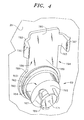
- First end section 63 is preferably domed-shaped so as to receive an inlet nozzle 69 therein (see Figure 4) as will be discussed more fully below.
- spray bar 60 includes a first end portion 90 that extends to a second end portion 91 through an intermediate portion 92 that defines a central trough 97.
- First and second end portions 90 and 91 actually define support members in a manner that will be detailed more fully below.
- spray bar 60 is actually fluidly connected to second end section 64 of inlet conduit 58 so as to receive a flow of washing fluid from inlet nozzle 69. The flow of washing fluid is directed outward from central trough 97 through a plurality of nozzles 104-111.
- trough 97 is divided into first and second lateral sections or zones 114 and 115 by a central support member 112, with nozzles 104-107 being positioned in first lateral zone 114 and nozzles 108-111 being positioned in second lateral zone 115.
- Upper washing mechanism 50 also includes a paddlewheel member 119 rotatably supported within trough 97 of spray bar 60.
- Paddlewheel member 119 actually includes a first paddle support 121 having a first end section 122 that extends to a second end section 123 through an intermediate section 124.
- First paddle support 121 is arranged within first lateral zone 114 of trough 97.
- second paddle support 129 Arranged alongside first paddle support 121, in second lateral zone 115, is a second paddle support 129.
- second paddle support 129 includes a first end section 130, a second end section 131 and an intermediate section 132.
- First and second paddle supports 121 and 129 are rotatably supported upon a central rod 135 that extends substantially the entire length of trough 97.
- central rod 135 includes first and second outer bearing elements 137 and 138 that are rotatably supported upon first and second end sections 90 and 91 of spray bar 60, as well as a central bearing/support portion 139 that rests upon central support member 112.
- first paddle support 121, 129 is substantially, identically constructed, a detailed description will be made with respect to first paddle support 121 with an understanding that second paddle support 129 is correspondingly constructed.
- First paddle support 121 includes a plurality of disk-shaped deflector members 145-147 positioned adjacent nozzles 104, 106 and 107 respectively, as well as a paddle-shaped deflector member 150 positioned adjacent to nozzle 105.
- a jet of washing fluid exiting nozzle 105 impacts paddle-shaped deflector member 150 causing first paddle support 121 to rotate about an axis defined by central rod 135.
- additional jets of washing fluid emanating from nozzles 104, 106 and 107 impact disk-shaped deflector members 145-147 respectively, causing the jets of washing fluid to diverge into streams of washing fluid which are directed onto kitchenware supported upon dishrack 30.
- inlet nozzle 69 includes a main body portion 160 having a base section 162, provided with a circular flange 163, which extends through an intermediate section 164 to a tapered or nozzle section 165.
- Nozzle section 165 is provided with a plurality of openings, one of which is indicated at 167, as well as a diffuser 169.
- Diffuser 169 includes an aperture 171 that receives a mechanical fastener 174 (see Figure 3) which secures upper washing mechanism 50 to washing chamber 28.
- mechanical fastener 174 see Figure 3
- upper washing mechanism 50 is also retained against rear wall 21 by a mounting bracket 184.
- mounting bracket 184 includes a main body 186 having a ring portion 188 from which extends an intermediate or planar portion 189 before terminating in a support portion 190.
- Support portion 190 includes first and second ear elements 192 and 193, each provided with a corresponding tab element 196, 197 that snap-fittingly engages inlet conduit 58.
- mounting bracket 184 is secured against rear wall 21 of washing chamber 28 through circular flange 163 of inlet nozzle 69.
- inlet nozzle 69 is connected to and receives a flow of washing fluid through an inlet feed member 206 extending through rear wall 21 of washing chamber 28.
- Inlet feed member 206 includes a conduit portion 208 and a base portion 210.
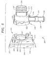
- Conduit portion 208 includes a main body section 214 having a base section 215 from which extend an inlet nipple 216 and an outlet nipple 217.
- Main body section 214 also includes a flange 222 having a pair of mounting ears, one of which is indicated at 225. As will be discussed more fully below, flange 222 acts as an interface between conduit portion 208 and base portion 210.
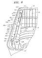
- Outlet nipple 217 includes a hollow interior portion 228 that leads into base section 215 and fluidly connects to inlet nipple 216. Outlet nipple 217 also includes a plurality of external threads 231 which, as best shown in Figure 6, engage with inlet nozzle 69. More specifically, outlet nipple 217 extends through rear wall 21 of washing chamber 28 and ring portion 188 of mounting bracket 184. Once in place, inlet nozzle 69 is secured to inlet feed member 206 through threads 231, with circular flange 163 trapping mounting bracket 184 against rear wall 21.
- inlet nipple 217 is shown to include a pair of outer rings 235 and 236 which provide a positive engagement for a hose 238 that is secured through a clamp 239 (see Figure 7).
- inlet feed member 206 receives a flow of washing fluid from a pump (not shown) through inlet nipple 216. The flow of washing fluid is thereafter redirected outward through outlet nipple 217 into inlet nozzle 69 and into spray bar 60.
- conduit portion 208 is supported upon a base portion 210 through flange 222.
- base member 210 is provided with a main housing 245 that includes a mounting member 247 and a cover 248.
- Mounting member 247 is provided with a pair of supports 260 and 261 that align with mounting ears 225. Supports 260 and 261 are adapted to receive mechanical fasteners, one of which is shown at 265, to secure conduit portion 208 to base portion 210.
- Mounting member 247 further includes a central opening 267 that leads into main housing 245.
- a seal 269 extends about central opening 267 and engages with flange 222 of conduit portion 208.
- cover 248 is pivotally connected to mounting member 247 through a hinge 270 and secured through a tab member 273.
- main housing 245 serves as an enclosure for electronic circuitry 280 (see Figure 7) associated with a flow sensor 283, such as a diaphragm positioned across central opening 267.
- Sensor 283 senses the flow of washing fluid through conduit portion 208 during an overall washing operation.
- an upper wash mechanism 350 includes a water delivery portion 356 having an inlet conduit 358 that is connected to a spray bar 360.
- Spray bar 360 includes a first end section 390 that extends to a second end section 391 through an intermediate section 392.
- arranged at intermediate section 392 is a "T" member 394 that directs a flow of washing fluid into a first lateral zone 360 and a second lateral zone 361.
- Each lateral zone 360, 361 includes a plurality of nozzles 404-406 and 407-409 respectively.
- Jets of washing fluid emanating from nozzles 404-409 impact upon a paddlewheel member 419 that is rotatably mounted to a pair of laterally spaced first and second support members 421 and 429.
- paddlewheel member 419 is provided with a pair of bearings, one of which is indicated at 438, that provide smooth rotation as paddlewheel 419 is impacted and rotated by jets of washing fluid emanating from nozzles 404-409.
- paddlewheel member 419 is provided with a slight twist or spiral which ensures continued exposure to the jets of washing fluid.
- paddlewheel member 419 constitutes an overall deflector member 445 that causes the jets of washing fluid to diverge into a plurality of streams which subsequently impact upon kitchenware supported upon dishrack 30 during an overall washing operation.
- the present invention provides for an efficient upper washing mechanism for directing water to an upper portion of a washing chamber in a drawer-type dishwasher. More particularly, mounting the upper washing mechanism to a wall of the wash chamber advantageously provides protection to various wash system components arranged within outer housing 4. More specifically, the particular positioning of the upper washing mechanism ensures that any residual water remaining within the wash system drops directly into the washing chamber and not onto various components carried within outer housing 4 as would be the case with a wash arm mounted to, for example, lid 37.
- the paddlewheel configuration establishes an extremely efficient and effective washing fluid distribution arrangement that creates streams of washing fluid sprayed randomly about the washing chamber.
Landscapes
- Washing And Drying Of Tableware (AREA)
Applications Claiming Priority (2)
| Application Number | Priority Date | Filing Date | Title |
|---|---|---|---|
| US79324506P | 2006-04-20 | 2006-04-20 | |
| US11/500,997 US7695571B2 (en) | 2006-04-20 | 2006-08-09 | Wash/rinse system for a drawer-type dishwasher |
Publications (3)
| Publication Number | Publication Date |
|---|---|
| EP1847207A2 true EP1847207A2 (de) | 2007-10-24 |
| EP1847207A3 EP1847207A3 (de) | 2007-12-26 |
| EP1847207B1 EP1847207B1 (de) | 2009-08-26 |
Family
ID=38291251
Family Applications (1)
| Application Number | Title | Priority Date | Filing Date |
|---|---|---|---|
| EP07106324A Not-in-force EP1847207B1 (de) | 2006-04-20 | 2007-04-17 | Wasch- und Spülsystem für einen schubladenartigen Geschirrspüler |
Country Status (5)
| Country | Link |
|---|---|
| US (2) | US7695571B2 (de) |
| EP (1) | EP1847207B1 (de) |
| CA (1) | CA2581543A1 (de) |
| DE (1) | DE602007002096D1 (de) |
| MX (1) | MX2007004669A (de) |
Cited By (2)
| Publication number | Priority date | Publication date | Assignee | Title |
|---|---|---|---|---|
| WO2011019740A3 (en) * | 2009-08-10 | 2011-08-04 | Electrolux Home Products, Inc. | Fluid circulation arrangement for providing an intensified wash effect in a dishwasher and an associated method |
| EP2695566A1 (de) * | 2012-08-08 | 2014-02-12 | Miele & Cie. KG | Geschirrspülautomat |
Families Citing this family (33)
| Publication number | Priority date | Publication date | Assignee | Title |
|---|---|---|---|---|
| US9918609B2 (en) | 2009-12-21 | 2018-03-20 | Whirlpool Corporation | Rotating drum filter for a dishwashing machine |
| US9687135B2 (en) | 2009-12-21 | 2017-06-27 | Whirlpool Corporation | Automatic dishwasher with pump assembly |
| US8627832B2 (en) | 2010-12-13 | 2014-01-14 | Whirlpool Corporation | Rotating filter for a dishwashing machine |
| US9119515B2 (en) | 2010-12-03 | 2015-09-01 | Whirlpool Corporation | Dishwasher with unitary wash module |
| US8667974B2 (en) | 2009-12-21 | 2014-03-11 | Whirlpool Corporation | Rotating filter for a dishwashing machine |
| ES1072252Y (es) * | 2010-04-08 | 2010-09-10 | Miquel Pujadas S A | Bandeja para lavaplatos |
| US9668636B2 (en) | 2010-11-16 | 2017-06-06 | Whirlpool Corporation | Method and apparatus for dishwasher with common heating element for multiple treating chambers |
| US9113766B2 (en) | 2010-11-16 | 2015-08-25 | Whirlpool Corporation | Method and apparatus for dishwasher with common heating element for multiple treating chambers |
| US20120138106A1 (en) * | 2010-12-03 | 2012-06-07 | Whirlpool Corporation | Dishwasher with single valve to fill multiple compartments |
| US9034112B2 (en) | 2010-12-03 | 2015-05-19 | Whirlpool Corporation | Dishwasher with shared heater |
| US8733376B2 (en) | 2011-05-16 | 2014-05-27 | Whirlpool Corporation | Dishwasher with filter assembly |
| US9107559B2 (en) | 2011-05-16 | 2015-08-18 | Whirlpool Corporation | Dishwasher with filter assembly |
| US9010344B2 (en) | 2011-06-20 | 2015-04-21 | Whirlpool Corporation | Rotating filter for a dishwashing machine |
| US9265401B2 (en) | 2011-06-20 | 2016-02-23 | Whirlpool Corporation | Rotating filter for a dishwashing machine |
| US9005369B2 (en) | 2011-06-20 | 2015-04-14 | Whirlpool Corporation | Filter assembly for a dishwasher |
| US9861251B2 (en) | 2011-06-20 | 2018-01-09 | Whirlpool Corporation | Filter with artificial boundary for a dishwashing machine |
| US20120318296A1 (en) | 2011-06-20 | 2012-12-20 | Whirlpool Corporation | Ultra micron filter for a dishwasher |
| US9301667B2 (en) | 2012-02-27 | 2016-04-05 | Whirlpool Corporation | Soil chopping system for a dishwasher |
| US9730570B2 (en) | 2012-05-30 | 2017-08-15 | Whirlpool Corporation | Reduced sound with a rotating filter for a dishwasher |
| US9237836B2 (en) | 2012-05-30 | 2016-01-19 | Whirlpool Corporation | Rotating filter for a dishwasher |
| US9532700B2 (en) | 2012-06-01 | 2017-01-03 | Whirlpool Corporation | Dishwasher with overflow conduit |
| US9833120B2 (en) | 2012-06-01 | 2017-12-05 | Whirlpool Corporation | Heating air for drying dishes in a dishwasher using an in-line wash liquid heater |
| US9451862B2 (en) | 2012-06-01 | 2016-09-27 | Whirlpool Corporation | Dishwasher with unitary wash module |
| US9554688B2 (en) | 2012-10-23 | 2017-01-31 | Whirlpool Corporation | Rotating filter for a dishwasher and methods of cleaning a rotating filter |
| US9848754B2 (en) * | 2012-11-19 | 2017-12-26 | Whirlpool Corporation | Dish rack with dispenser unit |
| US9440266B2 (en) | 2012-11-30 | 2016-09-13 | Steris Inc. | Washer / disinfector having a water inlet diffuser |
| KR20150080358A (ko) * | 2013-12-31 | 2015-07-09 | 삼성전자주식회사 | 식기세척기 |
| KR102079942B1 (ko) * | 2013-12-31 | 2020-02-21 | 삼성전자주식회사 | 식기 세척기 |
| US10750924B2 (en) * | 2016-03-24 | 2020-08-25 | Whirlpool Corporation | Dishwasher with tube wash system |
| US10279355B2 (en) | 2016-08-09 | 2019-05-07 | Superior Industries, Inc. | Hydraulic classifiers |
| USD904703S1 (en) | 2018-07-06 | 2020-12-08 | Heatworks Technologies, Inc. | Countertop dishwasher |
| USD918495S1 (en) | 2018-07-06 | 2021-05-04 | Heatworks Technologies, Inc. | Countertop dishwasher |
| US11759087B2 (en) | 2020-10-14 | 2023-09-19 | Whirlpool Corporation | Dishwasher paddle wheel assembly |
Family Cites Families (36)
| Publication number | Priority date | Publication date | Assignee | Title |
|---|---|---|---|---|
| US1477903A (en) | 1921-08-31 | 1923-12-18 | Rosenbaum Harry | Dishwashing apparatus |
| US1679062A (en) * | 1927-03-23 | 1928-07-31 | Alice B Payne | Dishwasher |
| US1916806A (en) | 1931-04-20 | 1933-07-04 | George H Myrick | Washing machine |
| US2436169A (en) * | 1941-08-29 | 1948-02-17 | Murray Corp | Dishwasher |
| US2586398A (en) | 1944-05-02 | 1952-02-19 | Ethan W Vars | Spray-type dish-washing machine having a circulating pump and plural rotatable strainer means selectively cooperable therewith |
| US2614886A (en) | 1948-05-01 | 1952-10-21 | Triumph Dishwashers Ltd | Liquid distributor |
| US2657095A (en) * | 1950-06-08 | 1953-10-27 | Lewis A James | Impeller assembly for dishwashers |
| US2704084A (en) * | 1953-10-19 | 1955-03-15 | James Inc | Dishwashing machine |
| US2905092A (en) | 1954-09-01 | 1959-09-22 | Gen Motors Corp | Domestic appliance |
| US3051182A (en) * | 1957-10-04 | 1962-08-28 | George M Gibson | Fluid circulating power means for a dishwashing machine |
| CH394530A (de) | 1961-02-22 | 1965-06-30 | Siemens Elektrogeraete Gmbh | Geschirrspülmaschine |
| US3255156A (en) * | 1961-05-01 | 1966-06-07 | Du Pont | Process for polymerizing thiocarbonyl compounds |
| FR1335909A (fr) * | 1961-10-12 | 1963-08-23 | Colston Ltd C | Machine à laver la vaisselle |
| US3207167A (en) | 1963-08-30 | 1965-09-21 | Gen Motors Corp | Top loading dishwashing apparatus |
| US3292645A (en) | 1964-10-13 | 1966-12-20 | Gen Motors Corp | Reaction spray dishwasher having an improved water fill system |
| US3288154A (en) | 1964-11-02 | 1966-11-29 | Gen Motors Corp | Plural compartment dishwasher with unitary pump |
| US3288156A (en) | 1964-11-19 | 1966-11-29 | Waste King Corp | Dishwasher with upwardly extensible distributor |
| US3368573A (en) * | 1965-10-07 | 1968-02-13 | Westinghouse Electric Corp | Dishwashing apparatus |
| US3348775A (en) | 1965-10-22 | 1967-10-24 | Gen Motors Corp | Reaction jet spray arm for dishwashers having simultaneous rotation about perpendicular axis |
| US3809106A (en) | 1972-08-23 | 1974-05-07 | Fedders Corp | Dishwasher with improved spray apparatus |
| US3912797A (en) * | 1973-04-10 | 1975-10-14 | Cherne Ind Inc | Liquid cooling apparatus and installations |
| US4014467A (en) * | 1975-11-03 | 1977-03-29 | Duff-Norton Company, Inc. | Dishwasher and coupling |
| US4208359A (en) * | 1979-01-29 | 1980-06-17 | The Marley Company | Low head non-clogging water distribution nozzle for cooling towers |
| US4773436A (en) | 1987-03-09 | 1988-09-27 | Cantrell Industries, Inc. | Pot and pan washing machines |
| EP0618779B1 (de) * | 1991-12-20 | 2000-05-03 | FISHER & PAYKEL LIMITED | Geschirrspülmaschine |
| NZ335414A (en) * | 1997-01-30 | 2000-10-27 | Fisher & Paykel | Dishwasher chamber having drain pump impeller with upper disc sealing against casing, and lower blade roots radially spaced from hub to allow air accumulation for priming |
| US6491049B1 (en) | 1998-09-21 | 2002-12-10 | Maytag Corporation | Lid construction for drawer dishwasher |
| US6460555B1 (en) | 1998-09-21 | 2002-10-08 | Maytag Corporation | Dual dishwasher construction |
| US6260565B1 (en) | 1998-09-21 | 2001-07-17 | Maytag Corporation | Double dishwasher |
| US6869029B2 (en) | 2002-04-02 | 2005-03-22 | Distinctive Appliances, Inc. | Water spray system for a dishwasher |
| US7225818B2 (en) * | 2002-04-02 | 2007-06-05 | Distinctive Appliances, Inc. | Water spraying device and system for dishwashers |
| US7445013B2 (en) * | 2003-06-17 | 2008-11-04 | Whirlpool Corporation | Multiple wash zone dishwasher |
| US7523758B2 (en) | 2003-06-17 | 2009-04-28 | Whirlpool Corporation | Dishwasher having rotating zone wash sprayer |
| US7475696B2 (en) | 2003-06-17 | 2009-01-13 | Whirlpool Corporation | Dishwasher having valved third-level sprayer |
| US20040255988A1 (en) * | 2003-06-17 | 2004-12-23 | Duhack Michael R. | Method and apparatus for sensing water flow through a dishwasher including a magnetic switch |
| US7426933B2 (en) | 2003-09-25 | 2008-09-23 | Maytag Corporation | Dishwasher with kinetic energy water distribution system |
-
2006
- 2006-08-09 US US11/500,997 patent/US7695571B2/en not_active Expired - Fee Related
-
2007
- 2007-03-12 CA CA002581543A patent/CA2581543A1/en not_active Abandoned
- 2007-04-17 EP EP07106324A patent/EP1847207B1/de not_active Not-in-force
- 2007-04-17 DE DE602007002096T patent/DE602007002096D1/de active Active
- 2007-04-18 MX MX2007004669A patent/MX2007004669A/es not_active Application Discontinuation
-
2010
- 2010-02-23 US US12/710,717 patent/US7985298B2/en not_active Expired - Fee Related
Cited By (3)
| Publication number | Priority date | Publication date | Assignee | Title |
|---|---|---|---|---|
| WO2011019740A3 (en) * | 2009-08-10 | 2011-08-04 | Electrolux Home Products, Inc. | Fluid circulation arrangement for providing an intensified wash effect in a dishwasher and an associated method |
| US9301670B2 (en) | 2009-08-10 | 2016-04-05 | Electrolux Home Products, Inc. | Fluid circulation arrangement for providing an intensified wash effect in a dishwasher and an associated method |
| EP2695566A1 (de) * | 2012-08-08 | 2014-02-12 | Miele & Cie. KG | Geschirrspülautomat |
Also Published As
| Publication number | Publication date |
|---|---|
| EP1847207B1 (de) | 2009-08-26 |
| EP1847207A3 (de) | 2007-12-26 |
| MX2007004669A (es) | 2008-12-01 |
| US7695571B2 (en) | 2010-04-13 |
| US20100139700A1 (en) | 2010-06-10 |
| US7985298B2 (en) | 2011-07-26 |
| US20070246078A1 (en) | 2007-10-25 |
| DE602007002096D1 (de) | 2009-10-08 |
| CA2581543A1 (en) | 2007-10-20 |
Similar Documents
| Publication | Publication Date | Title |
|---|---|---|
| EP1847207B1 (de) | Wasch- und Spülsystem für einen schubladenartigen Geschirrspüler | |
| US6869029B2 (en) | Water spray system for a dishwasher | |
| US9326657B2 (en) | Dual direction, double tier spray arm assembly for a dishwashing appliance | |
| US9839944B2 (en) | Dishwasher and control method thereof | |
| US20120291827A1 (en) | Spray tines for a dishwasher rack | |
| US8905053B2 (en) | Variable speed and multi-angle nozzle spray arm assembly for a dishwasher | |
| US10413152B2 (en) | Spray assemblies for dishwasher appliances | |
| US9861260B2 (en) | Dishwasher appliance and a tine assembly for a dishwasher appliance | |
| US20100101611A1 (en) | Dishwasher having multiple spray zones | |
| US20140069469A1 (en) | Dishwasher | |
| US8721804B2 (en) | Dishwasher with auxiliary washing agent dispensing system | |
| US11389043B2 (en) | Dishwasher spray arm assembly | |
| US20080116294A1 (en) | Spray devices and nozzles | |
| US7225818B2 (en) | Water spraying device and system for dishwashers | |
| CA2581770A1 (en) | Dispenser rinse system for a drawer-type dishwasher | |
| EP3813627B1 (de) | Geschirrspüler | |
| KR102493157B1 (ko) | 식기세척기 | |
| US11324381B2 (en) | Dish washer | |
| EP1568304B1 (de) | Geschirrspülmaschine | |
| US11445884B2 (en) | Dishwasher appliance main conduit with pressure relief hole |
Legal Events
| Date | Code | Title | Description |
|---|---|---|---|
| PUAI | Public reference made under article 153(3) epc to a published international application that has entered the european phase |
Free format text: ORIGINAL CODE: 0009012 |
|
| AK | Designated contracting states |
Kind code of ref document: A2 Designated state(s): AT BE BG CH CY CZ DE DK EE ES FI FR GB GR HU IE IS IT LI LT LU LV MC MT NL PL PT RO SE SI SK TR |
|
| AX | Request for extension of the european patent |
Extension state: AL BA HR MK YU |
|
| PUAL | Search report despatched |
Free format text: ORIGINAL CODE: 0009013 |
|
| AK | Designated contracting states |
Kind code of ref document: A3 Designated state(s): AT BE BG CH CY CZ DE DK EE ES FI FR GB GR HU IE IS IT LI LT LU LV MC MT NL PL PT RO SE SI SK TR |
|
| AX | Request for extension of the european patent |
Extension state: AL BA HR MK YU |
|
| 17P | Request for examination filed |
Effective date: 20080604 |
|
| 17Q | First examination report despatched |
Effective date: 20080703 |
|
| AKX | Designation fees paid |
Designated state(s): DE ES FR GB IT PL |
|
| GRAP | Despatch of communication of intention to grant a patent |
Free format text: ORIGINAL CODE: EPIDOSNIGR1 |
|
| GRAS | Grant fee paid |
Free format text: ORIGINAL CODE: EPIDOSNIGR3 |
|
| GRAA | (expected) grant |
Free format text: ORIGINAL CODE: 0009210 |
|
| AK | Designated contracting states |
Kind code of ref document: B1 Designated state(s): DE ES FR GB IT PL |
|
| REG | Reference to a national code |
Ref country code: GB Ref legal event code: FG4D |
|
| REF | Corresponds to: |
Ref document number: 602007002096 Country of ref document: DE Date of ref document: 20091008 Kind code of ref document: P |
|
| PG25 | Lapsed in a contracting state [announced via postgrant information from national office to epo] |
Ref country code: PL Free format text: LAPSE BECAUSE OF FAILURE TO SUBMIT A TRANSLATION OF THE DESCRIPTION OR TO PAY THE FEE WITHIN THE PRESCRIBED TIME-LIMIT Effective date: 20090826 |
|
| PG25 | Lapsed in a contracting state [announced via postgrant information from national office to epo] |
Ref country code: ES Free format text: LAPSE BECAUSE OF FAILURE TO SUBMIT A TRANSLATION OF THE DESCRIPTION OR TO PAY THE FEE WITHIN THE PRESCRIBED TIME-LIMIT Effective date: 20091207 |
|
| PLBE | No opposition filed within time limit |
Free format text: ORIGINAL CODE: 0009261 |
|
| STAA | Information on the status of an ep patent application or granted ep patent |
Free format text: STATUS: NO OPPOSITION FILED WITHIN TIME LIMIT |
|
| 26N | No opposition filed |
Effective date: 20100527 |
|
| REG | Reference to a national code |
Ref country code: FR Ref legal event code: ST Effective date: 20101230 |
|
| PG25 | Lapsed in a contracting state [announced via postgrant information from national office to epo] |
Ref country code: IT Free format text: LAPSE BECAUSE OF FAILURE TO SUBMIT A TRANSLATION OF THE DESCRIPTION OR TO PAY THE FEE WITHIN THE PRESCRIBED TIME-LIMIT Effective date: 20090826 |
|
| GBPC | Gb: european patent ceased through non-payment of renewal fee |
Effective date: 20110417 |
|
| PG25 | Lapsed in a contracting state [announced via postgrant information from national office to epo] |
Ref country code: GB Free format text: LAPSE BECAUSE OF NON-PAYMENT OF DUE FEES Effective date: 20110417 |
|
| PG25 | Lapsed in a contracting state [announced via postgrant information from national office to epo] |
Ref country code: FR Free format text: LAPSE BECAUSE OF NON-PAYMENT OF DUE FEES Effective date: 20100430 |
|
| PGFP | Annual fee paid to national office [announced via postgrant information from national office to epo] |
Ref country code: DE Payment date: 20180404 Year of fee payment: 12 |
|
| REG | Reference to a national code |
Ref country code: DE Ref legal event code: R119 Ref document number: 602007002096 Country of ref document: DE |
|
| PG25 | Lapsed in a contracting state [announced via postgrant information from national office to epo] |
Ref country code: DE Free format text: LAPSE BECAUSE OF NON-PAYMENT OF DUE FEES Effective date: 20191101 |