EP1847338A1 - Axial-Klemmstücksatz zur Herstellung von Agraffen für Deckel von Schaumwein u.a. - Google Patents
Axial-Klemmstücksatz zur Herstellung von Agraffen für Deckel von Schaumwein u.a. Download PDFInfo
- Publication number
- EP1847338A1 EP1847338A1 EP07006568A EP07006568A EP1847338A1 EP 1847338 A1 EP1847338 A1 EP 1847338A1 EP 07006568 A EP07006568 A EP 07006568A EP 07006568 A EP07006568 A EP 07006568A EP 1847338 A1 EP1847338 A1 EP 1847338A1
- Authority
- EP
- European Patent Office
- Prior art keywords
- guide
- cups
- cage
- axis
- cages
- Prior art date
- Legal status (The legal status is an assumption and is not a legal conclusion. Google has not performed a legal analysis and makes no representation as to the accuracy of the status listed.)
- Withdrawn
Links
Images


Classifications
-
- B—PERFORMING OPERATIONS; TRANSPORTING
- B21—MECHANICAL METAL-WORKING WITHOUT ESSENTIALLY REMOVING MATERIAL; PUNCHING METAL
- B21F—WORKING OR PROCESSING OF METAL WIRE
- B21F45/00—Wire-working in the manufacture of other particular articles
- B21F45/04—Wire-working in the manufacture of other particular articles of elements, e.g. levers or links, for bottle stoppers
Definitions
- the present invention relates to an axial-clamping assembly for the production of cages for tops for spumante wine or the like.
- the purpose of the present invention is to provide an axial-clamping assembly for the production of cages for tops for spumante wine or the like which will prevent any kind of sliding of or damage to the cage during its translation or movement from one processing station to another.
- the present invention achieves the aforesaid purpose by means of an axial-clamping assembly for the production of tops for spumante wine or the like presenting the characteristics recalled specifically in the ensuing claims.
- machines for the production and movement of cages for tops for spumante wine or the like in general have rather complex structures made up of numerous devices for movement of the cages from one workstation to another, and comprise a rotary table and a plurality of clamping devices provided with housings for cages set on the rotary table, and with fixed support against which the cages must slide in order not to be expelled in any way from the housings as a result of the centrifugal force due to rotation of the rotary table.
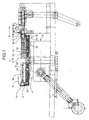
- the assembly 1 is associated to a rotary table 20 designed to be set in rotation about an axis A of rotation by a device D, which is in itself known and does not have any bearing upon the present invention, and comprises a fixed body 40, which is positioned axially above the rotary table 20 and is immobile with respect to the rotary table 20 itself.
- the assembly 1 moreover comprises a plurality of cups 10, which are uniformly distributed about the axis A and, as also illustrated in Figure 4, are fixed along the periphery of the rotary table 20 by means of screws 12 with hexagonal heads.
- Each cup 10 is provided with a respective substantially circular opening 10' made through a surface 10", radially facing the axis A, of the cup 10 itself, and is moreover provided with a respective recess 11, which substantially has the shape of a truncated cone increasing radially on the opposite side with respect to the axis A, has a respective axis 11' of processing lying in a radial direction towards the axis A and transverse thereto, and is designed for housing the body,3 of a cage 2 so that the four legs 4 of the body 3 are inclined by 45° with respect to the axis 11' of processing and so that an annular head 5 of the cage 2 comes out of the opening 10' by a given amount, any radial displacement in the direction of the axis A of the cage 2 itself
- each cup 10 is designed to cause advance of the cages 2 along a path P which extends through an insertion and torsion assembly 60, an unloading station S, set downstream of the assembly 60 along the path P, and a station C, set in a position intermediate between the insertion and torsion assembly 60 and the station S.
- the assembly 1 is designed to keep each body 3 in the corresponding cup 10 in a position of conveyance, preventing it from coming out owing to the centrifugal force exerted on the body 3 itself and following upon rotation of the table 20.
- the assembly 1 is designed to prevent, by means of the recesses 11 and their particular truncated-cone shape, a displacement of the cages 2 towards the axis A and along the axis 11' and, as will be described in greater detail in what follows, is likewise designed to prevent also any displacement of the cages 2 once again along the axis 11' in a direction opposite to the axis A, consequently ensuring maintenance of the position of conveyance of each cage 2 within its own recess 11.
- the assembly 1 moreover comprises a guide 31, mounted on the fixed body 40 and defined by a cylindrical wall 31', which extends about the axis A throughout an arc of amplitude substantially of 180° terminating in a position corresponding to the station C, and is radially delimited outwards by a surface 31" facing the surfaces 10" of the cups 10.
- the cylindrical wall 31' is provided with a plurality of pairs of seats 32', uniformly distributed about the axis A and housed within each of which is a magnetized body or permanent magnet 32.
- the seats 32' of each pair of seats 32' are set in a position symmetrical with respect to a horizontal median line M of the guide 31 identified by the intersection of the axes 11' of processing with the cylindrical wall 31'.
- the guide 31, i.e., its own surface 31" is set, throughout its arc of 180°, at a constant radial distance from the surfaces 10" of the cups 10 and, in any case, at a distance such that the annular head 5 of the cages 2 is always set in the radial space comprised between the surfaces 31" and 10" in all the points of rotation in order to prevent any possible sliding and friction of the annular heads 5 against the guide 31.
- the force exerted by the magnetized bodies 32 on the annular heads 5 is designed to overcome the centrifugal force caused by the rotation of the rotary table 20 and enables the bodies 3 of the cages 2 to be kept in their position of conveyance, with the legs 4 set within the corresponding recess 11 and with the annular head 5 set just outside of the recess 11 through the window 10', likewise enabling advance of the cages 2 to the subsequent workstations.
- a mechanical anchorage 33 comprising a top tab 34 and a bottom tab 35, set in a point corresponding to the processing and torsion assembly 60, where the girdle or brace 7 is inserted in the body 3 of the cage 2.
- the mechanical anchorage 33 is necessary since during return into the position of rest of the assembly 60 for insertion and torsion of the girdle or brace 7, with the rotary table 20 stationary, the force Fy directed outwards from the table 20 is much greater than the centrifugal force Fx produced by the table 20 itself in rotation. In fact, the assembly 60 that comes out after processing exerts on the body 3 of the cage 2 a force much greater than the centrifugal force that originates on the cage 2 during rotation of the table 20.
- the system of mechanical anchorage 33 equipped with tabs 34, 35 enables the body 3 of the cage 2 to remain in position on the cup 10 during movement towards the point of rest of the assembly 60 for insertion of the girdle or brace 7, enabling rotation of the table 20.
- the assembly on account of the force exerted by the magnetized elements 32, overcomes in a relatively easy way the centrifugal force Fx but is unable to overcome the force Fy exerted mechanically by the moving assembly 60. From the foregoing, it emerges that the annular head 5 of the cage 2 is in contact with the tabs 34, 35 of the system of mechanical anchorage 33 so as to overcome a force Fy directed outwards.
- each cage 2 Once each cage 2 has been equipped with the corresponding girdle or brace 7, it is fed through the station C, in a position corresponding to which the cap 6 is inserted in the corresponding body 3, after which, in step-by-step fashion, each cage 2 is made to advance through an arc of amplitude of approximately 90° up to the station S to enable it to be unloaded from the table 20 onto another table (not described or represented), where the operations prior to packaging proceed.
- the assembly 1 comprises a further guide 51, which is mounted on the fixed body 40 between the stations C and S and is defined by a respective cylindrical wall 51', which extends about the axis A for an arc of amplitude substantially of approximately 90°, and is radially delimited outwards by a surface 51" facing the surfaces 10" of the cups 10.
- the cylindrical wall 51' is moreover provided with a plurality of seats 52' uniformly distributed about the axis A and within each of which a magnetized body or permanent magnet 52 is housed, designed to exert a force greater than the centrifugal force to which each cage 2 is subjected during rotation of the rotary table 20 between the stations C and S.
- the seats 52' are set in a substantially aligned position in a respective radial direction with respect to the openings 10' of the cups 10, i.e., they are set along the median line M of the guide 51, whilst the guide 51, i.e., its own surface 51", is set, throughout its arc of 90°, at a constant radial distance from the surfaces 10" of the cups 10 and, in any case, at a distance such that the cap 6 of the cages 2 is once again set in the radial space comprised between the surfaces 51" and 10" in all the points of rotation in order to prevent any possible sliding and friction of the caps 6 against the guide 51.
- the cages 2 are without the corresponding caps 6, it is necessary to have available a plurality of magnetized bodies 31 set above the median line M and schematically acting on a top portion of the annular heads 5, and a plurality of magnetized bodies 31 set beneath the median line M and schematically acting on a bottom portion of the annular heads 5: the simultaneous magnetic action of the magnetized bodies 31 or each pair of magnetized bodies 31 results in a force of magnetic attraction directed in any case along each axis 11' and designed to counter the effect of the centrifugal force on each cage 2 owing to the rotation of the rotary table 20.
Landscapes
- Engineering & Computer Science (AREA)
- Mechanical Engineering (AREA)
- Specific Conveyance Elements (AREA)
Applications Claiming Priority (1)
| Application Number | Priority Date | Filing Date | Title |
|---|---|---|---|
| ITTO20060238 ITTO20060238A1 (it) | 2006-03-30 | 2006-03-30 | Complesso di bloccaggio assiale per la fabbricazione di gabbiette per tappi di spumante o simili |
Publications (1)
| Publication Number | Publication Date |
|---|---|
| EP1847338A1 true EP1847338A1 (de) | 2007-10-24 |
Family
ID=38461787
Family Applications (1)
| Application Number | Title | Priority Date | Filing Date |
|---|---|---|---|
| EP07006568A Withdrawn EP1847338A1 (de) | 2006-03-30 | 2007-03-29 | Axial-Klemmstücksatz zur Herstellung von Agraffen für Deckel von Schaumwein u.a. |
Country Status (2)
| Country | Link |
|---|---|
| EP (1) | EP1847338A1 (de) |
| IT (1) | ITTO20060238A1 (de) |
Cited By (1)
| Publication number | Priority date | Publication date | Assignee | Title |
|---|---|---|---|---|
| ITTO20100628A1 (it) * | 2010-07-21 | 2012-01-22 | Nuova Tecnologia Meccanica S R L | Meccanismo di centraggio su mezzi di trasporto delle gabbiette per tappi di bottiglie di bevande spumanti |
Citations (5)
| Publication number | Priority date | Publication date | Assignee | Title |
|---|---|---|---|---|
| DE2411109B1 (de) * | 1974-03-08 | 1975-07-31 | Otto Sick Kg, 7830 Emmendingen | Vorrichtung zum Aufsetzen von vierstrebigen Drahtverschlüssen |
| DE3817229C1 (de) * | 1988-05-20 | 1990-01-25 | Imc-Sondermaschinenbau, 6550 Bad Kreuznach, De | |
| EP0366955A1 (de) * | 1988-11-03 | 1990-05-09 | Otto Sick Gmbh | Aufsetzvorrichtung für Drahtverschlüsse |
| EP0389859A1 (de) * | 1989-03-31 | 1990-10-03 | Draht- und Metallwarenfabrik Phillip Schneider GmbH & Co. | Anordung zum Transportieren von in einer Reihe von angeordneten Sektflaschendrahtbügeln |
| EP0808793A1 (de) * | 1996-05-21 | 1997-11-26 | Gefin S.r.l. | Förderer zur schrittweisen Förderung von Produkten zwischen aufeinanderfolgenden Bearbeitungsmaschinen |
-
2006
- 2006-03-30 IT ITTO20060238 patent/ITTO20060238A1/it unknown
-
2007
- 2007-03-29 EP EP07006568A patent/EP1847338A1/de not_active Withdrawn
Patent Citations (5)
| Publication number | Priority date | Publication date | Assignee | Title |
|---|---|---|---|---|
| DE2411109B1 (de) * | 1974-03-08 | 1975-07-31 | Otto Sick Kg, 7830 Emmendingen | Vorrichtung zum Aufsetzen von vierstrebigen Drahtverschlüssen |
| DE3817229C1 (de) * | 1988-05-20 | 1990-01-25 | Imc-Sondermaschinenbau, 6550 Bad Kreuznach, De | |
| EP0366955A1 (de) * | 1988-11-03 | 1990-05-09 | Otto Sick Gmbh | Aufsetzvorrichtung für Drahtverschlüsse |
| EP0389859A1 (de) * | 1989-03-31 | 1990-10-03 | Draht- und Metallwarenfabrik Phillip Schneider GmbH & Co. | Anordung zum Transportieren von in einer Reihe von angeordneten Sektflaschendrahtbügeln |
| EP0808793A1 (de) * | 1996-05-21 | 1997-11-26 | Gefin S.r.l. | Förderer zur schrittweisen Förderung von Produkten zwischen aufeinanderfolgenden Bearbeitungsmaschinen |
Cited By (1)
| Publication number | Priority date | Publication date | Assignee | Title |
|---|---|---|---|---|
| ITTO20100628A1 (it) * | 2010-07-21 | 2012-01-22 | Nuova Tecnologia Meccanica S R L | Meccanismo di centraggio su mezzi di trasporto delle gabbiette per tappi di bottiglie di bevande spumanti |
Also Published As
| Publication number | Publication date |
|---|---|
| ITTO20060238A1 (it) | 2007-09-30 |
Similar Documents
| Publication | Publication Date | Title |
|---|---|---|
| US11155423B2 (en) | Beverage bottle holding and transport device for holding and transporting beverage bottles and similar containers | |
| EP3639848A3 (de) | Stabilisierte proteinfreie clostridientoxinzusammensetzungen | |
| US20100071830A1 (en) | Method of labeling bottles and containers in a bottle or container filling plant, and a bottle or container labeling arrangement therefor | |
| DK2687101T3 (en) | Apparatus for processing poultry, comprising one or more transfer units | |
| EP2813445B1 (de) | Vorrichtung und Verfahren zur Handhabung von Probenröhrchen und Laborsystem | |
| KR200480974Y1 (ko) | 행거 자동 회전 장치 | |
| RU2015104713A (ru) | Станок и гибкий производственный модуль для установки направляющих втулок и седел клапанов | |
| CN111056296A (zh) | 工件输送装置 | |
| CN104575863A (zh) | 电子导线二次成型多工位转盘及成型系统和方法 | |
| WO2018085608A3 (en) | Automated high speed metallographic system | |
| KR910008169B1 (ko) | 계란등의 피처리물의 이체장치 | |
| HRP20241386T1 (hr) | Držač za čaše i način njegovog sastavljanja | |
| EP4272909A3 (de) | Vorrichtung, system und verfahren für eine luftlagerstufe für komponenten oder vorrichtungen | |
| US20160361451A1 (en) | Installation de sterilisation d'articles par rayonnement | |
| EP3597573B1 (de) | Werkstückträger für behälter in einer behandlungsmaschine einer abfüllanlage und verfahren zum transport und zur positionierung der behälter | |
| CN105575647A (zh) | 用于连续将电磁铁磁轭压装在底板上的装置 | |
| WO2017198768A3 (de) | Höhenförderer | |
| CN102958818A (zh) | 具有辊支承件的容器定向保持器和容器定向方法 | |
| EP1944102A1 (de) | Haltevorrichtung für eine Fördereinrichtung für Sicherheitskäfige für Flaschendeckel für Brausegetränke | |
| CN107161604B (zh) | 一种规则几何形工件输送带上的夹紧装置 | |
| US20160001986A1 (en) | Installation de transport de recipients | |
| DE10153069A1 (de) | Vorrichtung zum Vereinzeln von Getränkeflaschen mit Halskragen | |
| JP4641745B2 (ja) | 丸くない容器の検査に関連して使用される機械 | |
| MX2018001828A (es) | Montaje de eje balanceador. | |
| CN103785889A (zh) | 一种金属管切割机 |
Legal Events
| Date | Code | Title | Description |
|---|---|---|---|
| PUAI | Public reference made under article 153(3) epc to a published international application that has entered the european phase |
Free format text: ORIGINAL CODE: 0009012 |
|
| AK | Designated contracting states |
Kind code of ref document: A1 Designated state(s): AT BE BG CH CY CZ DE DK EE ES FI FR GB GR HU IE IS IT LI LT LU LV MC MT NL PL PT RO SE SI SK TR |
|
| AX | Request for extension of the european patent |
Extension state: AL BA HR MK YU |
|
| 17P | Request for examination filed |
Effective date: 20080409 |
|
| AKX | Designation fees paid |
Designated state(s): AT BE BG CH CY CZ DE DK EE ES FI FR GB GR HU IE IS IT LI LT LU LV MC MT NL PL PT RO SE SI SK TR |
|
| RAP1 | Party data changed (applicant data changed or rights of an application transferred) |
Owner name: BREVETTI E TECNOLOGIA S.R.L. |
|
| STAA | Information on the status of an ep patent application or granted ep patent |
Free format text: STATUS: THE APPLICATION IS DEEMED TO BE WITHDRAWN |
|
| 18D | Application deemed to be withdrawn |
Effective date: 20101001 |