EP1847366A2 - Fördergerät und Verfahren zur Herstellung einer Wabenstruktur - Google Patents
Fördergerät und Verfahren zur Herstellung einer Wabenstruktur Download PDFInfo
- Publication number
- EP1847366A2 EP1847366A2 EP07007870A EP07007870A EP1847366A2 EP 1847366 A2 EP1847366 A2 EP 1847366A2 EP 07007870 A EP07007870 A EP 07007870A EP 07007870 A EP07007870 A EP 07007870A EP 1847366 A2 EP1847366 A2 EP 1847366A2
- Authority
- EP
- European Patent Office
- Prior art keywords
- wet mixture
- conveyer
- moisture content
- conveyance
- honeycomb structure
- Prior art date
- Legal status (The legal status is an assumption and is not a legal conclusion. Google has not performed a legal analysis and makes no representation as to the accuracy of the status listed.)
- Granted
Links
Images


Classifications
-
- B—PERFORMING OPERATIONS; TRANSPORTING
- B28—WORKING CEMENT, CLAY, OR STONE
- B28B—SHAPING CLAY OR OTHER CERAMIC COMPOSITIONS; SHAPING SLAG; SHAPING MIXTURES CONTAINING CEMENTITIOUS MATERIAL, e.g. PLASTER
- B28B13/00—Feeding the unshaped material to moulds or apparatus for producing shaped articles; Discharging shaped articles from such moulds or apparatus
- B28B13/02—Feeding the unshaped material to moulds or apparatus for producing shaped articles
-
- B—PERFORMING OPERATIONS; TRANSPORTING
- B01—PHYSICAL OR CHEMICAL PROCESSES OR APPARATUS IN GENERAL
- B01J—CHEMICAL OR PHYSICAL PROCESSES, e.g. CATALYSIS OR COLLOID CHEMISTRY; THEIR RELEVANT APPARATUS
- B01J35/00—Catalysts, in general, characterised by their form or physical properties
- B01J35/50—Catalysts, in general, characterised by their form or physical properties characterised by their shape or configuration
- B01J35/56—Foraminous structures having flow-through passages or channels, e.g. grids or three-dimensional [3D] monoliths
- B01J35/57—Honeycombs
-
- B—PERFORMING OPERATIONS; TRANSPORTING
- B65—CONVEYING; PACKING; STORING; HANDLING THIN OR FILAMENTARY MATERIAL
- B65G—TRANSPORT OR STORAGE DEVICES, e.g. CONVEYORS FOR LOADING OR TIPPING, SHOP CONVEYOR SYSTEMS OR PNEUMATIC TUBE CONVEYORS
- B65G47/00—Article or material-handling devices associated with conveyors; Methods employing such devices
- B65G47/52—Devices for transferring articles or materials between conveyors i.e. discharging or feeding devices
- B65G47/72—Devices for transferring articles or materials between conveyors i.e. discharging or feeding devices transferring materials in bulk from one conveyor to several conveyors, or vice versa
-
- B—PERFORMING OPERATIONS; TRANSPORTING
- B65—CONVEYING; PACKING; STORING; HANDLING THIN OR FILAMENTARY MATERIAL
- B65G—TRANSPORT OR STORAGE DEVICES, e.g. CONVEYORS FOR LOADING OR TIPPING, SHOP CONVEYOR SYSTEMS OR PNEUMATIC TUBE CONVEYORS
- B65G65/00—Loading or unloading
- B65G65/30—Methods or devices for filling or emptying bunkers, hoppers, tanks, or like containers, of interest apart from their use in particular chemical or physical processes or their application in particular machines, e.g. not covered by a single other subclass
- B65G65/34—Emptying devices
- B65G65/40—Devices for emptying otherwise than from the top
- B65G65/42—Devices for emptying otherwise than from the top using belt or chain conveyors
-
- C—CHEMISTRY; METALLURGY
- C04—CEMENTS; CONCRETE; ARTIFICIAL STONE; CERAMICS; REFRACTORIES
- C04B—LIME, MAGNESIA; SLAG; CEMENTS; COMPOSITIONS THEREOF, e.g. MORTARS, CONCRETE OR LIKE BUILDING MATERIALS; ARTIFICIAL STONE; CERAMICS; REFRACTORIES; TREATMENT OF NATURAL STONE
- C04B35/00—Shaped ceramic products characterised by their composition; Ceramics compositions; Processing powders of inorganic compounds preparatory to the manufacturing of ceramic products
- C04B35/515—Shaped ceramic products characterised by their composition; Ceramics compositions; Processing powders of inorganic compounds preparatory to the manufacturing of ceramic products based on non-oxide ceramics
- C04B35/56—Shaped ceramic products characterised by their composition; Ceramics compositions; Processing powders of inorganic compounds preparatory to the manufacturing of ceramic products based on non-oxide ceramics based on carbides or oxycarbides
- C04B35/565—Shaped ceramic products characterised by their composition; Ceramics compositions; Processing powders of inorganic compounds preparatory to the manufacturing of ceramic products based on non-oxide ceramics based on carbides or oxycarbides based on silicon carbide
-
- C—CHEMISTRY; METALLURGY
- C04—CEMENTS; CONCRETE; ARTIFICIAL STONE; CERAMICS; REFRACTORIES
- C04B—LIME, MAGNESIA; SLAG; CEMENTS; COMPOSITIONS THEREOF, e.g. MORTARS, CONCRETE OR LIKE BUILDING MATERIALS; ARTIFICIAL STONE; CERAMICS; REFRACTORIES; TREATMENT OF NATURAL STONE
- C04B35/00—Shaped ceramic products characterised by their composition; Ceramics compositions; Processing powders of inorganic compounds preparatory to the manufacturing of ceramic products
- C04B35/622—Forming processes; Processing powders of inorganic compounds preparatory to the manufacturing of ceramic products
- C04B35/626—Preparing or treating the powders individually or as batches ; preparing or treating macroscopic reinforcing agents for ceramic products, e.g. fibres; mechanical aspects section B
- C04B35/62605—Treating the starting powders individually or as mixtures
- C04B35/62625—Wet mixtures
- C04B35/6263—Wet mixtures characterised by their solids loadings, i.e. the percentage of solids
-
- C—CHEMISTRY; METALLURGY
- C04—CEMENTS; CONCRETE; ARTIFICIAL STONE; CERAMICS; REFRACTORIES
- C04B—LIME, MAGNESIA; SLAG; CEMENTS; COMPOSITIONS THEREOF, e.g. MORTARS, CONCRETE OR LIKE BUILDING MATERIALS; ARTIFICIAL STONE; CERAMICS; REFRACTORIES; TREATMENT OF NATURAL STONE
- C04B37/00—Joining burned ceramic articles with other burned ceramic articles or other articles by heating
- C04B37/003—Joining burned ceramic articles with other burned ceramic articles or other articles by heating by means of an interlayer consisting of a combination of materials selected from glass, or ceramic material with metals, metal oxides or metal salts
- C04B37/005—Joining burned ceramic articles with other burned ceramic articles or other articles by heating by means of an interlayer consisting of a combination of materials selected from glass, or ceramic material with metals, metal oxides or metal salts consisting of glass or ceramic material
-
- C—CHEMISTRY; METALLURGY
- C04—CEMENTS; CONCRETE; ARTIFICIAL STONE; CERAMICS; REFRACTORIES
- C04B—LIME, MAGNESIA; SLAG; CEMENTS; COMPOSITIONS THEREOF, e.g. MORTARS, CONCRETE OR LIKE BUILDING MATERIALS; ARTIFICIAL STONE; CERAMICS; REFRACTORIES; TREATMENT OF NATURAL STONE
- C04B38/00—Porous mortars, concrete, artificial stone or ceramic ware; Preparation thereof
- C04B38/0006—Honeycomb structures
-
- C—CHEMISTRY; METALLURGY
- C04—CEMENTS; CONCRETE; ARTIFICIAL STONE; CERAMICS; REFRACTORIES
- C04B—LIME, MAGNESIA; SLAG; CEMENTS; COMPOSITIONS THEREOF, e.g. MORTARS, CONCRETE OR LIKE BUILDING MATERIALS; ARTIFICIAL STONE; CERAMICS; REFRACTORIES; TREATMENT OF NATURAL STONE
- C04B2111/00—Mortars, concrete or artificial stone or mixtures to prepare them, characterised by specific function, property or use
- C04B2111/00474—Uses not provided for elsewhere in C04B2111/00
- C04B2111/00793—Uses not provided for elsewhere in C04B2111/00 as filters or diaphragms
-
- C—CHEMISTRY; METALLURGY
- C04—CEMENTS; CONCRETE; ARTIFICIAL STONE; CERAMICS; REFRACTORIES
- C04B—LIME, MAGNESIA; SLAG; CEMENTS; COMPOSITIONS THEREOF, e.g. MORTARS, CONCRETE OR LIKE BUILDING MATERIALS; ARTIFICIAL STONE; CERAMICS; REFRACTORIES; TREATMENT OF NATURAL STONE
- C04B2235/00—Aspects relating to ceramic starting mixtures or sintered ceramic products
- C04B2235/02—Composition of constituents of the starting material or of secondary phases of the final product
- C04B2235/30—Constituents and secondary phases not being of a fibrous nature
- C04B2235/38—Non-oxide ceramic constituents or additives
- C04B2235/3817—Carbides
- C04B2235/3826—Silicon carbides
-
- C—CHEMISTRY; METALLURGY
- C04—CEMENTS; CONCRETE; ARTIFICIAL STONE; CERAMICS; REFRACTORIES
- C04B—LIME, MAGNESIA; SLAG; CEMENTS; COMPOSITIONS THEREOF, e.g. MORTARS, CONCRETE OR LIKE BUILDING MATERIALS; ARTIFICIAL STONE; CERAMICS; REFRACTORIES; TREATMENT OF NATURAL STONE
- C04B2235/00—Aspects relating to ceramic starting mixtures or sintered ceramic products
- C04B2235/02—Composition of constituents of the starting material or of secondary phases of the final product
- C04B2235/50—Constituents or additives of the starting mixture chosen for their shape or used because of their shape or their physical appearance
- C04B2235/54—Particle size related information
- C04B2235/5418—Particle size related information expressed by the size of the particles or aggregates thereof
- C04B2235/5436—Particle size related information expressed by the size of the particles or aggregates thereof micrometer sized, i.e. from 1 to 100 micron
-
- C—CHEMISTRY; METALLURGY
- C04—CEMENTS; CONCRETE; ARTIFICIAL STONE; CERAMICS; REFRACTORIES
- C04B—LIME, MAGNESIA; SLAG; CEMENTS; COMPOSITIONS THEREOF, e.g. MORTARS, CONCRETE OR LIKE BUILDING MATERIALS; ARTIFICIAL STONE; CERAMICS; REFRACTORIES; TREATMENT OF NATURAL STONE
- C04B2235/00—Aspects relating to ceramic starting mixtures or sintered ceramic products
- C04B2235/02—Composition of constituents of the starting material or of secondary phases of the final product
- C04B2235/50—Constituents or additives of the starting mixture chosen for their shape or used because of their shape or their physical appearance
- C04B2235/54—Particle size related information
- C04B2235/5418—Particle size related information expressed by the size of the particles or aggregates thereof
- C04B2235/5445—Particle size related information expressed by the size of the particles or aggregates thereof submicron sized, i.e. from 0,1 to 1 micron
-
- C—CHEMISTRY; METALLURGY
- C04—CEMENTS; CONCRETE; ARTIFICIAL STONE; CERAMICS; REFRACTORIES
- C04B—LIME, MAGNESIA; SLAG; CEMENTS; COMPOSITIONS THEREOF, e.g. MORTARS, CONCRETE OR LIKE BUILDING MATERIALS; ARTIFICIAL STONE; CERAMICS; REFRACTORIES; TREATMENT OF NATURAL STONE
- C04B2235/00—Aspects relating to ceramic starting mixtures or sintered ceramic products
- C04B2235/60—Aspects relating to the preparation, properties or mechanical treatment of green bodies or pre-forms
- C04B2235/602—Making the green bodies or pre-forms by moulding
- C04B2235/6021—Extrusion moulding
-
- C—CHEMISTRY; METALLURGY
- C04—CEMENTS; CONCRETE; ARTIFICIAL STONE; CERAMICS; REFRACTORIES
- C04B—LIME, MAGNESIA; SLAG; CEMENTS; COMPOSITIONS THEREOF, e.g. MORTARS, CONCRETE OR LIKE BUILDING MATERIALS; ARTIFICIAL STONE; CERAMICS; REFRACTORIES; TREATMENT OF NATURAL STONE
- C04B2237/00—Aspects relating to ceramic laminates or to joining of ceramic articles with other articles by heating
- C04B2237/02—Aspects relating to interlayers, e.g. used to join ceramic articles with other articles by heating
- C04B2237/04—Ceramic interlayers
- C04B2237/08—Non-oxidic interlayers
- C04B2237/083—Carbide interlayers, e.g. silicon carbide interlayers
-
- C—CHEMISTRY; METALLURGY
- C04—CEMENTS; CONCRETE; ARTIFICIAL STONE; CERAMICS; REFRACTORIES
- C04B—LIME, MAGNESIA; SLAG; CEMENTS; COMPOSITIONS THEREOF, e.g. MORTARS, CONCRETE OR LIKE BUILDING MATERIALS; ARTIFICIAL STONE; CERAMICS; REFRACTORIES; TREATMENT OF NATURAL STONE
- C04B2237/00—Aspects relating to ceramic laminates or to joining of ceramic articles with other articles by heating
- C04B2237/30—Composition of layers of ceramic laminates or of ceramic or metallic articles to be joined by heating, e.g. Si substrates
- C04B2237/32—Ceramic
- C04B2237/36—Non-oxidic
- C04B2237/365—Silicon carbide
-
- F—MECHANICAL ENGINEERING; LIGHTING; HEATING; WEAPONS; BLASTING
- F01—MACHINES OR ENGINES IN GENERAL; ENGINE PLANTS IN GENERAL; STEAM ENGINES
- F01N—GAS-FLOW SILENCERS OR EXHAUST APPARATUS FOR MACHINES OR ENGINES IN GENERAL; GAS-FLOW SILENCERS OR EXHAUST APPARATUS FOR INTERNAL-COMBUSTION ENGINES
- F01N2330/00—Structure of catalyst support or particle filter
- F01N2330/30—Honeycomb supports characterised by their structural details
-
- F—MECHANICAL ENGINEERING; LIGHTING; HEATING; WEAPONS; BLASTING
- F01—MACHINES OR ENGINES IN GENERAL; ENGINE PLANTS IN GENERAL; STEAM ENGINES
- F01N—GAS-FLOW SILENCERS OR EXHAUST APPARATUS FOR MACHINES OR ENGINES IN GENERAL; GAS-FLOW SILENCERS OR EXHAUST APPARATUS FOR INTERNAL-COMBUSTION ENGINES
- F01N2450/00—Methods or apparatus for fitting, inserting or repairing different elements
- F01N2450/28—Methods or apparatus for fitting, inserting or repairing different elements by using adhesive material, e.g. cement
-
- F—MECHANICAL ENGINEERING; LIGHTING; HEATING; WEAPONS; BLASTING
- F01—MACHINES OR ENGINES IN GENERAL; ENGINE PLANTS IN GENERAL; STEAM ENGINES
- F01N—GAS-FLOW SILENCERS OR EXHAUST APPARATUS FOR MACHINES OR ENGINES IN GENERAL; GAS-FLOW SILENCERS OR EXHAUST APPARATUS FOR INTERNAL-COMBUSTION ENGINES
- F01N3/00—Exhaust or silencing apparatus having means for purifying, rendering innocuous, or otherwise treating exhaust
- F01N3/02—Exhaust or silencing apparatus having means for purifying, rendering innocuous, or otherwise treating exhaust for cooling, or for removing solid constituents of, exhaust
- F01N3/021—Exhaust or silencing apparatus having means for purifying, rendering innocuous, or otherwise treating exhaust for cooling, or for removing solid constituents of, exhaust by means of filters
- F01N3/022—Exhaust or silencing apparatus having means for purifying, rendering innocuous, or otherwise treating exhaust for cooling, or for removing solid constituents of, exhaust by means of filters characterised by specially adapted filtering structure, e.g. honeycomb, mesh or fibrous
- F01N3/0222—Exhaust or silencing apparatus having means for purifying, rendering innocuous, or otherwise treating exhaust for cooling, or for removing solid constituents of, exhaust by means of filters characterised by specially adapted filtering structure, e.g. honeycomb, mesh or fibrous the structure being monolithic, e.g. honeycombs
Definitions
- the present invention relates to a conveyer apparatus, and a method for manufacturing a honeycomb structure.
- a honeycomb structure when manufacturing a honeycomb structure, first, for example, a ceramic powder, a binder, and a liquid dispersing medium and the like are mixed together to prepare a wet mixture.
- the wet mixture is then extrusion molded continuously by using a die, and the extruded molded body is cut to a prescribed length to produce a rectangular pillar-shaped honeycomb molded body.
- the honeycomb molded body obtained above is dried using microwave drying or hot-air drying, and afterward, prescribed cells are sealed to achieve a sealed state of the cells in which either end of the cells are sealed by the plug material layer. After the sealed state has been achieved, degreasing and firing treatments are carried out, thus producing the honeycomb fired body.
- a sealing material paste is applied onto the side faces of the honeycomb fired body, and honeycomb fired bodies are adhered together to prepare an aggregate of honeycomb fired bodies in which a multitude of honeycomb fired bodies are bonded together by interposing a sealing material layer (an adhesive layer).
- Cutting process is then carried out to obtain a ceramic block using a cutting machine or the like and cutting the obtained aggregate of honeycomb fired bodies into a prescribed form, such as cylindrical or cylindroid form and the like.
- sealing material paste is applied on the periphery of the ceramic block to form a sealing material layer (a coat layer), thus completing the manufacturing of the honeycomb structure.
- the present invention has been devised for the purpose of solving these problems. It is an object of the present invention to provide a conveyer apparatus which enables a small rate of moisture content change of the wet mixture between before and after the conveyance process and enables to supply the wet mixture with a constant quality for the following process. It is also an object of the present invention, particularly in cases used in production of a honeycomb structure, to provide a conveyer apparatus able to prevent cracks and cell cut-off from occurring in extrusion molded bodies, and a method for manufacturing a honeycomb structure in which cracks and cell cut-off do not occur in extrusion molded bodies extruded in the extrusion molding process.
- the conveyer apparatus of the present invention comprises a conveyer portion having disposed therein a conveyer configured to convey a wet mixture; wherein rate of moisture content change of the wet mixture between before after conveyance is 3% or less.
- the above mentioned conveyer apparatus comprise a storage portion for temporarily storing the wet mixture, and it is also preferable that the above mentioned conveyer portion be formed by a casing and a belt conveyer disposed inside of the above mentioned casing.
- a partition member configured to partition off the interior of the casing is disposed near the end portion of the downstream side of the belt conveyer.
- the method for manufacturing a honeycomb structure comprising a honeycomb fired body according to the present invention comprises:
- the above mentioned conveyer apparatus further comprises:
- the above mentioned conveyer portion constituting the above mentioned conveyer apparatus is formed by a casing; and a belt conveyer disposed inside of the casing.
- a partition member configured to partition off the interior of the casing is disposed near the end portion of the downstream side of the belt conveyer constituting the above mentioned conveyer apparatus.
- the moisture content of the above mentioned wet mixture used in the above mentioned method for manufacturing a honeycomb structure is in the range of 10 to 20% by weight after conveyance.
- the conveyer apparatus of the present invention is able to prevent drying of the wet mixture during the conveyance process, as well as to keep the rate of moisture content change of the wet mixture between before and after conveyance to 3% or less. Because of this, it is possible to supply wet mixture of a constant degree of quality to the subsequent processes in a stable manner. Also, in cases of using the conveyer apparatus of the present invention as the conveyer apparatus used before the extrusion molding process in the manufacturing processes of a honeycomb structure for example, because it is possible to supply wet mixture having a suitable moisture content to the extrusion molding apparatus in a stable manner, it is possible to prevent cracks, cell cut-off and the like from occurring in the extrusion molded body.
- the partition member configured to partition the interior of the casing when used near the end portion of the downstream side of the belt conveyer constituting the conveyer apparatus, it is possible to effectively prevent drying of the wet mixture inside of the conveyer apparatus while further reducing the rate of moisture content change of the wet mixture between before and after conveyance process.
- the method for manufacturing a honeycomb structure according to the present invention since it is possible to keep the rate of moisture content change of the wet mixture between before and after conveyance process to 3% or less, it is possible to supply wet mixture having a suitable moisture content to the extrusion molding apparatus in a stable manner, it is possible to prevent cracks, cell cut-off and the like from occurring in the extrusion molded body.
- the moisture content of the wet mixture after conveyance is in the range of 10 to 20% by weight, it is possible to attain an extrusion molded body that has no occurrence of cracks, cell cut-off or the like, and maintains a constant shape.
- the conveyer apparatus comprises a conveyer portion having disposed therein a conveyer configured to convey a wet mixture; wherein rate of moisture content change of the wet mixture between before and after conveyance is 3% or less.
- rate of moisture content change of the wet mixture between before and after conveyance is 3% or less.
- 'rate of moisture content change of the wet mixture between before and after conveyance is 3% or less' means absolute value of the rate of moisture content change of the wet mixture between before and after conveyance is 3% or less.
- Fig. 1 is a cross sectional view schematically showing an example of the conveyer apparatus according to the present invention.
- This conveyer apparatus 30 comprises a conveyer portion 32 configured to convey wet mixture.
- the conveyer portion 32 comprises a casing 33 having a charging port 34 for the purpose of charging a wet mixture, and a belt conveyer 35.
- a wet mixture prepared in a wet mixing apparatus (not shown) is charged into the conveyer portion 32 from the charging port 34, it is deposited on the belt conveyer 35 constituting the conveyer portion 32.
- the conveyer apparatus 30 is constituted in such a manner that the casing 33 entirely covers the belt conveyer 35 and its surroundings and the entirety of the conveyer portion 32 can be hermetically enclosed. In this manner, with regard to the region between the interior and the exterior of the casing 33, it is possible to prevent the moisture contained in the air within the casing 33 from moving out of the casing 33. Because of this, if a prescribed amount of moisture evaporates from the wet mixture inside of the casing 33, thereby once increasing the humidity level of inside of the casing 33, it is possible to subsequently maintain this state of a high humidity inside the casing 33.
- the rate of evaporation of the moisture from the wet mixture inside of the casing 33 per unit time decreases by charging the wet mixture into the casing 33 while inceimpulsly maintaining the state of high humidity inside of the casing 33, it is possible to decrease the amount of the moisture evaporating inside of the casing 33 thereby preventing the drying of the wet mixture. Due to the above mentioned operation, since it is possible to prevent the drying of the wet mixture from occurring inside of the conveyer portion 32, it is thereby possible to conduct conveyance in such a manner that the rate of moisture content change of the wet mixture between before and after conveyance process is kept to 3% or less. Also, it is preferable that the rate of moisture content change of the wet mixture between before and after conveyance process is lower, more preferably as close to 0% as possible.
- the conveyer portion 32 is formed by the casing 33 and the belt conveyer 35 disposed inside of the casing 33.
- the 'casing 33' includes a casing having a box-shaped member with a lid disposed thereon, and a casing pre-formed as a tube-shaped member.
- the casing 33 be a material having a low water permeability. With a material having a high water permeability, it is impossible to prevent moisture from moving between the interior and the exterior of the casing 33, making it unable to serve its purpose.
- the material be a metal, and the kind of metal is not particularly limited.
- a partition member 38 configured to partition off the interior of the casing 33 near the end portion of the downstream side of the belt conveyer 35.
- This partition member 38 is installed in such a manner that its top end is able to rotate over a prescribed angle around a shaft 38a as a center which is disposed on the face of the top plate of the casing 33.
- This partition member 38 is able to partition off the interior of the casing 33, and is able to thereby prevent the moisture from moving between partitioned spaces. With this, it is possible to even more narrowly partition off the space in which the wet mixture exists and thus hold the humidity level of the partitioned space high. By holding the humidity level of the space in which the wet mixture exists high, it is possible to reduce the amount of moisture evaporating from the wet mixture and thereby even further reduce the rate of moisture content change of the wet mixture between before and after conveyance process.
- the top end of the partition member 38 is able to rotate over a prescribed angle around the shaft 38a as a center which is disposed on the face of the top plate of the casing 33, when force is applied to the front end of the partition member 38 by the wet mixture moving on a belt 35a, the partition member 38 rotates slightly around the shaft 38a in the direction of movement of the belt 35a, thereby making it possible to convey the wet mixture in a state in which the end portion of the partition member 38 is in contact with the surface of the wet mixture.
- the material of the partition member 38 is not particularly limited, it is preferable that it be a material having low moisture permeability and low water absorption properties. With a material having a high moisture permeability property, it is not possible to prevent the movement of moisture between the partitioned spaces, and thus to fulfill its role. Also, with a material having a high water absorption property, since the moisture contained in the wet mixture is absorbed by the partition member 38, and the moisture content of the wet mixture thereby decreases, thus again, it does not accomplish its purpose as a partition member. Specifically, resin materials having a low water absorption coefficient such as fluorine resin, or metal materials are preferable.
- the thickness of the partition member 38 is not particularly limited, it is preferable to adjust the thickness, in consideration of the relationship with the water permeability of the partition member 38, to such an extent that moisture cannot permeate the partition member 38. Also, it is preferable that the partition member 38 be a material having bendability. This is because when force is applied to the partition member 38 by the wet mixture moving on the belt 35a, the front end of the partition member 38 can bend and thereby does not become a hindrance to the movement of the wet mixture, making it possible to conduct conveyance in a state in which the partition member 38 is in contact with the surface of the wet mixture.
- partition members 38 it is acceptable to dispose a plurality of the partition members 38 over the conveyance path of the wet mixture. By disposing a plurality of the partition members 38, it is possible to even more narrowly partition off spaces in which the wet mixture exists, thereby making it possible to prevent drying of the wet mixture within the partitioned spaces.
- the belt conveyer 35 is constituted by a belt 35a, and rollers 36a, 36b, and can convey the wet mixture (not shown) deposited on the belt conveyer 35 in the direction of the downstream side of the belt conveyer 35 in a continuous or intermittent manner.
- the material of the belt 35a is not particularly limited. Examples of the material of the belt 35a include resins such as rubber, urethane, vinyl-chloride, fluorine resin, silicone resin, and the like.
- the storage portion 31A and storage portion 31B are disposed on both end sides of the belt conveyer 35.
- the storage portion 31A has on its bottom face an openable and closable discharging port.
- the storage portion 31A can temporarily store a given amount of wet mixture while supplying, under control, wet mixture at a constant amount per unit time from its discharging port to the apparatus of the next process, for example a process of producing a molded body by an extrusion molding apparatus.
- the storage portion 31A has an open/close plate 37 slidable in the left and right directions.
- this open/close plate 37 By setting this open/close plate 37 into a closed state (the state depicted in Fig. 1), it is possible to set the storage portion 31A apart from other regions of the conveyer apparatus 30. In this way, since it is possible to narrowly partition off the space in which the stored wet mixture exists, it is possible to prevent the drying of the wet mixture stored within the storage portion 31A. In cases in which the conveyer apparatus 30 is not working, and the supply of the wet mixture to the storage portion 31A is suspended, setting the open/close plate 37 into a closed state is effective in the prevention of drying of the wet mixture.
- the conveyer apparatus 30 by reversing the direction of rotation of the rollers 36a, 36b, it is possible to convey the wet mixture deposited on the belt conveyer 35 to the storage portion 31B situated on the opposite side of the storage portion 31A in a continuous or intermittent manner, thereby storing the wet mixture in the storage portion 31B.
- the storage portion 31B also has on its bottom face an openable and closable discharging port, thereby making it possible to temporarily store a given amount of wet mixture while supplying, under control, wet mixture at a constant amount per unit time from its discharging port to the apparatus of the next process.
- the storage portion 31B also has the open/close plate 37, making it possible to prevent drying of the wet mixture in the storage portion 31B.
- the conveyer portion 32 comprises a distribution mechanism. Also, in cases in which the wet mixture is distributed and supplied to two extrusion molding apparatuses, it is possible to select the amount of the wet mixture to be allocated among the apparatuses by adjusting factors such as the movement speed of the belt conveyer 35, and the running time and the like in the forward and reverse rotation directions. Also, it is acceptable to simply select how much of the wet mixture is to be sent to either storage in an appropriate manner.
- the storage portion 31A and the storage portion 31B since it is possible for the storage portion 31A and the storage portion 31B to fulfill a role as a buffer, even in cases in which in the wet mixing machine (not shown), which is at the process preceding the conveyer apparatus 30, mixing is continuous and the wet mixture is charged into the conveyer apparatus 30 in a continuous manner while the operation of the subsequent process is currently stopped, it is possible to maintain that state just as it is if the period of time in question is relatively short.
- the conveyer apparatus 30 shown in Fig. 1 is a conveyer apparatus comprising a distribution mechanism, and the distribution mechanism is disposed on the conveyer portion 32.
- the structure of the conveyer apparatus according to the present invention is not limited to this kind, as it is possible for instance to have a structure mentioned below.
- Fig. 2 is a cross sectional view schematically showing another example of the conveyer apparatus according to the present invention.
- the conveyer apparatus 50 shown in Fig. 2 is one comprising a conveyer portion 52 and a storage portion 51
- the conveyer apparatus 50 differs from the conveyer apparatus 30 shown in Fig. 1 at the point of comprising the storage portion 51 in the upstream side from the conveyer portion 52 in the conveyance path of the wet mixture.
- the conveyer apparatus 50 comprises the conveyer portion 52 configured to convey the wet mixture, and the storage portion 51 for temporarily storing the wet mixture.
- the conveyer portion 52 comprises a casing 53, and belt conveyers 55A, 55B.
- Discharging ports 51a, 51b disposed at the bottom face of the storage portion 51 are in communication with the top face of the casing 53, and it is possible to charge the wet mixture into the interior of the casing 53 through the discharging port 51a and the discharging port 51b.
- the conveyer apparatus 50 in the same manner as in the conveyer apparatus 30 shown in Fig. 1, is constituted in a manner that the casing 53 is disposed to entirely cover the belt conveyer 55A, the belt conveyer 55B and their surroundings and the entirety of the conveyer portion 52 can be hermetically enclosed.
- the conveyer apparatus 50 since it is possible to prevent the moisture contained in the air within the casing 53 from moving out of the casing 53 and to prevent the drying of the wet mixture in the conveyer portion 52, it is possible to conduct conveying of the wet mixture while retaining the moisture content of the wet mixture so that the rate of moisture content change of the wet mixture between before and after conveyance process is kept to 3% or less.
- a partition member 58 for partitioning the interior of the casing 53 near the end portion of the downstream side of each of the belt conveyer 55A and the belt conveyer 55B. With this, it is possible to even more narrowly partition off the space in which the wet mixture exists and thereby even further reduce the rate of moisture content change of the wet mixture within the space partitioned off.
- the belt conveyer 55A (constituted by the belt 155a and rollers 56a, 56b), and the belt conveyer 55B (constituted by the belt 155b and rollers 56c, 56d) are disposed, and each of the belt conveyer 55A and belt conveyer 55B is constituted in such a manner that it can convey the wet mixture toward the end portion side of the casing 53.
- the storage portion 51 has an open/close plate 57 slidable in the left and right directions.
- This open/close plate 57 By setting this open/close plate 57 into a closed state (the state depicted in Fig. 2), it is possible to divide the interior space of the storage portion 51 into an upper portion and a lower portion.
- the portion on the lower side of the storage portion 51 divided by the open/close plate 57 comprises at its bottom face the discharging ports 51a, 51b at two places, thereby comprising a distribution mechanism for discharging the wet mixture from only one of the discharging ports.
- a shaft member 59b is installed at a bifurcation point between the discharging port 51a and the discharging port 51b in a manner able to rotate, and one side of a plate-shaped switch plate 59a is fixed onto this shaft member 59b.
- This switch plate 59a is constituted in a manner able to move over a prescribed angle according to the rotation of the shaft member 59b.
- this kind of storage portion 51 in a case in which the open/close plate 57 is closed, it is possible to store wet mixture prepared within a wet mixing machine (not shown) in the upper portion (the portion above the open/close plate 57, in Fig. 2). Also, in a case in which the charge of the wet mixture from the wet mixing machine is currently stopped, it is effective, in the prevention of drying of the wet mixture, to dispose an open/close plate or the like at a wet mixture charging port 54 to close the charging port 54 thereby narrowly partitioning off the space in which the wet mixture exists.
- the amount of the wet mixture to be discharged from either the discharging port 51a or the discharging port 51b can be adjusted by adjusting the degree of openness of the open/close plate 57. Also, by using a vibrator or the like, it is possible to apply vibrations to thereby force wet mixture to fall in a small amount at a time, and by adjusting the strength of the vibrations, it is possible to control the amount of the wet mixture discharged from either the discharging port 51a or the discharging port 51b.
- this storage portion 51 it is possible to temporarily store the wet mixture in the portion above the open/close plate 57 by closing the open/close plate 57, distribute the wet mixture by selecting which discharging port to open (or close off) by the switch plate 59a, and thereby conduct charge of the wet mixture into the interior of the casing 53. More specifically, in a case in which the discharging port 51a of the storage portion 51 is opened, wet mixture is deposited on the belt 155a, and in a case in which the discharging port 51b is opened, the wet mixture is deposited on the belt 155b.
- the storage portion 51 comprises a storage mechanism and a distribution mechanism.
- the wet mixture deposited on each the belt 155a and the belt 155b is conveyed in its prescribed direction by the belt conveyer 55A and the belt conveyer 55B, it is supplied to the apparatus of the next process through a discharging port 53a and a discharging port 53b disposed on the casing 53.
- the conveyer apparatuses explained above with reference to Figs. 1 and 2 are conveyer apparatuses comprising storage portions on either the upstream side or the downstream side of the conveyer portion, it is acceptable if the conveyer apparatus according to the present invention does not even comprise a storage portion, or it comprises storage portions on both the upstream and the downstream sides of the conveyer portion. Also, although in the conveyer apparatuses of Figs. 1 and 2, either the conveyer portion or the storage portion comprises a distribution mechanism, it is acceptable not to comprise a distribution mechanism, or to alternately comprise distribution mechanisms at both the conveyer portion as well as the storage portion. Also, in a case in which the conveyer apparatus according to the present invention comprises a distribution mechanism, the distribution destinations are not limited to be two sites, but can also be three or more.
- the conveyer apparatuses shown in Figs. 1 and 2 comprise belt conveyers using flat-plane belts as the conveyer
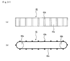
- the conveyer of the conveyer apparatus according to the present invention is not limited to this, and, for instance, may be the one shown in Fig. 3-1(a), 3-1(b), 3-2 (a) or 3-2(b) .
- FIG. 3-1(a) and Fig. 3-2(a) are plan views each schematically showing another example of a conveyer constituting the conveyer apparatus according to the present invention while Fig. 3-1 (b) and Fig. 3-2 (b) are cross sectional views corresponding to Figs. 3-1(a) and 3-2(a), respectively.
- a conveyer 65 shown in Figs. 3-1(a) and 3-1 (b) comprises a cleat type conveyer belt 65a and rollers 66a, 66b. Disposed on the cleat type conveyer belt 65a in the direction roughly perpendicular to the direction of movement of the belt are plate-shaped protrusions 65b.
- the conveyer portion comprising the conveyer 65 comprises a casing, although not shown, similar to the one shown in Fig. 1 or Fig. 2.
- the shape of the cleat type conveyer belt 65a is not particularly limited. By disposing these cleats on the belt, it is possible to conduct conveyance without the wet mixture flowing downward past the surrounding cleats even in cases in which there is an incline present in the conveyance path.
- the material of the cleat type conveyer belt 65a is not particularly limited, and may for example include resins such as rubber, urethane, vinyl-chloride, fluorine resin, silicone resin, and the like.
- a conveyer 75 shown in Figs. 3-2(a) and 3-2(b) is a bucket-mounted chain conveyer, and comprises a bucket-mounted chain 75a, and rollers 76a, 76b. Fixed to the bucket-mounted chain 75a at regular intervals on the surface of the chain are buckets 75b for holding wet mixture.
- the conveyer portion comprising the conveyer 75 comprises a casing, although not shown, similar to the one shown in Fig. 1 or Fig. 2.
- the shape of the bucket-mounted chain 75a is not particularly limited.
- the shape and material of the bucket are not particularly limited. By disposing the buckets, it is possible to conduct conveyance of wet mixture even in cases in which there is an incline present in the conveyance path or it is necessary to convey in vertical directions.
- the material of the chain 75a is not particularly limited, and may for example include resins such as rubber, urethane, vinyl-chloride, fluorine resin, silicone resin, as well as metal materials. These kinds of conveyers shown in Figs. 3-1(a), 3-1(b), 3-2(a) and 3-2(b) can also be used favorably in the conveyer portion constituting the conveyer apparatus according to the present invention.
- the conveyer apparatus according to the present invention to use as the conveyer constituting its conveyer portion a chain conveyer, a pallet conveyer, a trolley conveyer, a flow conveyer, a flight conveyer, a disc conveyer, a power screw, a screw conveyer, or the like, for instance.
- the method for manufacturing a honeycomb structure according to the present invention a method for manufacturing a honeycomb structure comprising a honeycomb fired body comprising:
- Fig. 6 is a perspective view schematically showing an example of a honeycomb structure.
- Fig. 7(a) is a perspective view schematically showing a honeycomb fired body which forms the above-mentioned honeycomb structure, while Fig. 7 (b) is an A-A line cross-sectional view thereof.
- a honeycomb fired body 140 In a honeycomb structure 130, a plurality of honeycomb fired bodies 140, of the kind shown in Fig. 6, are combined with one another by interposing a sealing material layer (an adhesive layer) 131 forming a ceramic block 133, and a sealing material layer (a coat layer) 132 is formed on the periphery of the ceramic block 133.
- the honeycomb fired body 140 comprises, as shown in Figs. 7(a) and 7(b), a multitude of cells 141 placed in parallel in the longitudinal direction, and cell walls 143, which partition the cells 141 individually, and provide filtration functionality.
- the end portion of either the exhaust gas inlet side or the exhaust gas outlet side of the cells 141 formed in the honeycomb fired body 140 are sealed by a plug material layer 142.
- the exhaust gas which enters one cell 141 passes through the cell walls 143 dividing the cells 141 without fail, to flow out through another cell 141.
- particulates contained within the exhaust gas are captured by the cell wall 143, thus purifying the exhaust gas.
- a method for manufacturing a honeycomb structure according to the present invention will be described in process order.
- a method for manufacturing a honeycomb structure in a case wherein silicon carbide powder is used as inorganic powder as an example of a case in which a honeycomb structure chiefly comprising silicon carbide as a main component is manufactured.
- the main component of the honeycomb structure is not limited to silicon carbide, and may be nitride ceramics such as aluminum nitride, silicon nitride, boron nitride, and titanium nitride, carbide ceramics such as zirconium carbide, titanium carbide, tantalum carbide, and tungsten carbide, oxide ceramics such as alumina, zirconia, cordierite, mullite, aluminum titanate, and the like.
- non-oxide ceramics are preferable, and silicon carbide is particularly preferable. This is because they are excellent in thermal resistance, mechanical strength, thermal conductivity and the like.
- silicon-containing ceramic which is the above-mentioned ceramic blended with metallic silicon, as well as ceramic bonded by silicon or silicate compounds can also be used as the constitutional material.
- silicon carbide blended with metallic silicon silicon-containing silicon carbide is preferable.
- organic binder is dry mixed with an inorganic powder such as silicon carbide powder having a varying average particle diameter to prepare a powder blend.
- a liquid blend is prepared by blending liquid plasticizer, lubricating agent, and water.
- the above mentioned powder blend and the above mentioned liquid blend are further blended together using a wet mixing machine, and thus a wet mixture for manufacturing the molded body is prepared.
- the particle diameter of the above mentioned silicon carbide powder is not particularly limited, a particle diameter causing little shrinkage in the following firing process is preferable, and for example, a combination of 100 parts by weight of powders having an average particle diameter of 0.3 to 50 ⁇ m, and 5 to 65 parts by weight of powders having an average particle diameter of 0.1 to 1.0 ⁇ m is preferable.
- the pore diameter can also be adjusted by adjusting the particle diameter of the inorganic powder.
- the above-mentioned organic binder is not particularly limited, and examples thereof may include methyl cellulose, carboxymethyl cellulose, hydroxyethyl cellulose, polyethylene glycol and the like. Among these, methyl cellulose is preferable. It is preferable that the above mentioned binder be blended with the inorganic powder at a ratio of around 1 to 10 weight of binder per 100 weight of inorganic powder.
- the above-mentioned plasticizer is not particularly limited, and examples thereof may include glycerin and the like.
- the above-mentioned lubricant is not particularly limited, and examples thereof may include polyoxyalkylene compounds such as polyoxyethylene alkyl ether, polyoxypropylene alkyl ether, and the like. Specific examples of the lubricant may include, polyoxyethylene monobutyl ether, polyoxypropylene monobutyl ether and the like. Also, in some cases, it is unnecessary to use plasticizer or lubricating agent in the material powder blend.
- a liquid dispersing medium such as water, organic solvents such as benzene, and alcohol such as methanol.
- a molding auxiliary is not limited in particular, and examples thereof may include ethylene glycol, dextrin, fatty acids, fatty acid soap, polyalcohol, or the like.
- balloons which are micro-sized hollow spherical bodies containing oxide ceramic as component, and pore-forming agent such as a spherical acrylic particle or graphite to the above-mentioned wet mixture, if necessary.
- the above-mentioned balloon is not particularly limited, and examples thereof may include alumina balloon, glass micro balloon, shirasu balloon, fly ash balloon (FA balloon), mullite balloon and the like. Among these, alumina balloon is preferable.
- the wet mixture prepared here using silicon carbide powder is preferably at a temperature of 28°C or less. If the temperature that is too high, the organic binder may gelate. Also, it is preferable that the proportion of organic component within the above mentioned wet mixture be 10% by weight or less.
- the above mentioned wet mixture is conveyed after preparation and supplied to a molding apparatus.
- a conveyer apparatus capable of keeping the rate of moisture content change of the wet mixture between before and after conveyance to 3% or less is used.
- the desirable value of the moisture content within the wet mixture is as follows: the desirable lower limit is 10% by weight, more desirably 12% by weight.
- the desirable upper limit is 20% by weight, more desirably 15% by weight. This is because if the moisture content is less than 10% by weight, cracks, cell cut-off and the like easily occur in the molded body, while if the moisture content exceeds 20% by weight, it is difficult for the extruded molded body to maintain a constant shape until it is dried. For this reason, it is necessary to control the moisture content of the wet mixture within the above mentioned range.
- the extrusion molding process using the extrusion molding apparatus mentioned hereinafter is a process that first sets various conditions such as the molding force, molding speed, and the like optimized in accordance with the theoretical moisture content value obtained when mixing the wet mixture supplied to the extrusion molding apparatus, and then conducts extrusion molding with those set condition.
- the extrusion molding conditions are not suitable to attain a molded body of a constant level of quality if the divergence of the theoretical value of the above mentioned moisture content with the actual measured value is great, cracks, cell cut-off and the like may occur in the molded body, or possibly the extruded molded body cannot maintain a constant shape until it is dried.
- the method for manufacturing a honeycomb structure when conveying the prepared wet mixture, it is desirable to store the above mentioned wet mixture in the above mentioned storage portion for a given period of time. This is because the moldability of the wet mixture is improved in the subsequent extrusion molding process. The reason for this is not clear, but it is thought to lie in that when the above mentioned wet mixture is thus stored, it is cooled and aged, and during this time of cooling and aging, the organic binder undergoes swelling and the lubricative properties of the inorganic powder (silicon carbide powder) improves.
- the storage time period is not particularly limited, it is desirable that the lower limit be 1 hour, and is even more desirable if the lower limit is 4 hours. It is desirable that the upper limit of the storage time period be 10 hours, and is even more desirable if the upper limit is 8 hours. This is because, if the storage time period is less than 1 hour, there will be little improvement in the moldability of the wet mixture, and if the storage time period exceeds 10 hours, portions of the wet mixture will undergo drying which will actually adversely degrade the moldability of the wet mixture.
- the extrusion molding process is carried out.
- the extrusion molding apparatus used in the extrusion molding process in the method for manufacturing a honeycomb structure according to the present invention is not particularly limited, explanation will be given hereinbelow concerning an example of an extrusion molding apparatus and an extrusion molding method using the same with reference to the figures.
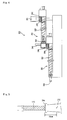
- Fig. 4 is a cross sectional view schematically showing an example of the extrusion molding apparatus used in the extrusion molding process.
- This extrusion molding apparatus 220 comprises two screw mixers including an upper tier screw mixer 241 and a lower tier screw mixer 261.
- a screw comprising an agitation shaft (screw shaft) and an agitation blade (screw blade) is disposed in each the upper tier screw mixer 241 and the lower tier screw mixer 261.
- a charge hopper 231 Disposed on one end portion of the above mentioned upper tier screw mixer 241 is a charge hopper 231 configured to take in a pre-mixed raw material wet mixture, and disposed in a reception port 249 on the bottom of the charge hopper 231 is a knead-press roller 242 configured to press the wet mixture into the interior of the upper tier screw mixer 241.
- the knead-press roller 242 presses the wet mixture that has fallen down through the charge hopper 231 in between a pair of knead-press rollers while kneading the wet mixture, and thereafter pushes the wet mixture out of the underside of the rollers by rotating inwardly, thereby supplying the wet mixture to the interior of the upper tier screw mixer 241.
- the upper tier screw mixer 241 comprises an upper tier screw 243 comprising a feed screw and a take screw disposed at the front end of the feed screw.
- the feed screw has a role of moving the wet mixture while kneading the same, and the take screw is configured mainly to knead the wet mixture.
- a screw blade agitation blade
- the wet mixture is both kneaded and pushed out in a forward direction.
- the take blade there are a plurality of screw blades formed on the screw shaft in a manner forming a ring around the circumferential direction of the screw shaft, and there is a portion that is disconnected in a slanting direction and has no screw blade. Kneading of the wet mixture proceeds further while the wet mixture passes through this portion.
- an upper tier die Situated on the other end of the upper tier screw mixer 241 is an upper tier die (mouth-piece) having a multitude of through holes formed thereon. After passing through the take screw, the wet mixture is pressed into this upper tier die and is extruded in a state in which the wet mixture is shaped like a rod or Japanese noodle, for instance.
- a decompression chamber 246, Disposed on the portion at which the wet mixture is extruded from the upper tier die is a decompression chamber 246, the interior of which is in a state of decompression nearing a vacuum state.
- the interior of the upper tier screw mixer 241 and the lower tier screw mixer 261 are also held in a state of decompression so as not to trap bubbles (air) in the wet mixture. If bubbles are trapped in the wet mixture, it becomes easy for defects caused by bubbles situated inside of the partition walls and the like to occur when producing the molded body.
- an upper tier cutter 245 used as a cutting member. More specifically, the blade of the upper tier cutter 245 is situated in the interior of the decompression chamber 246, and this blade portion is set into reciprocating motion in the up/down directions near the upper tier die by an air cylinder disposed on the decompression chamber 246, in a manner cutting the wet mixture, which has been extruded from the upper tier die in a Japanese noodle shape (or rod shape), into smaller pieces.
- the multitude of cut small pieces immediately fall into a reception port 269 of the underlying lower tier screw mixer 261, and are pressed into the interior of the lower tier screw mixer 261 by a knead-press roller 262 (which is constituted in a manner similar to the above described knead-press roller 242) . In this way, the mixing of the wet mixture proceeds further.
- the lower tier screw mixer 261 comprises a lower tier screw 263 comprising a feed screw and a W blade screw disposed on the front of the feed screw. At the front end portion the wet mixture is pressed quantitatively into a die 264. In this manner, by repeating the action of kneading, the mixing of the wet mixture proceeds sufficiently, and the wet mixture thereby takes the form of a composite exhibiting uniformity in its moisture content, composition, and the like, and is then extruded in a continuous manner from the die 264 to form a continuous rectangular pillar-shaped molded body with a plurality of cells in the longitudinal direction.
- the wet mixture is pressed into the screw mixer by the knead-press machine, it is also acceptable for the wet mixture to be pressed into the screw mixer by another means, and it is also acceptable to only form a charge hopper.
- the assembly arrangement of the screws disposed in the interior of the screw mixer is not limited to the above described assembly arrangement. It is also acceptable, for example, to constitute the screw with feed screws only, or another assembly arrangement is acceptable.
- the time period until it is extruded be in the range of 50 to 90 minutes. This is because it is necessary to achieve a sufficient degree of mixing and to obtain an entirely uniform composition such as moisture and the like. Also, during extrusion molding it is desirable that the speed at which the molded body is extruded be in the range of 3500 to 4500 mm/min. At a speed of less than 3500 mm/min, the production efficiency drops, thus the speed is unfavorable, and at an extrusion speed exceeding 4500 mm/min, it becomes difficult to obtain the honeycomb molded body with the designed dimensions and defects easily occur in the produced honeycomb molded body. Regarding these molding conditions, it is necessary to set the optimum values in accordance with the theoretical value of the moisture content at the time of preparation of the wet mixture.
- the above mentioned honeycomb molded body is dried out. Then, if necessary, the end portion of the outlet side of the group of inlet cells as well as the end portion of the inlet side of the group of outlet cells are filled with a prescribed amount of plug material paste which will serve as plugs, thereby plugging the cells.
- a drying apparatus such as a microwave drying apparatus, a hot air drying apparatus, a dielectric drying apparatus, a reduced pressure drying apparatus, a vacuum drying apparatus, or a freeze drying apparatus.
- plug material paste is not particularly limited, one which makes the porosity of the plug material manufactured in the subsequent processes in the range of 30% to 75% is preferable. It is possible to use for instance a substance identical to the above-mentioned wet mixture as the plug material paste.
- degreasing at 200°C to 500°C, for example
- firing at 1400°C to 2300°C, for example
- a honeycomb fired body comprising a plurality of cells placed in parallel with one another in the longitudinal direction with a cell wall therebetween, and either end portion of each cell is plugged.
- the conditions for degreasing and firing the above-mentioned honeycomb molded body it is possible to apply conventional conditions used for manufacturing a filter comprising porous ceramic.
- the sealing material paste which will serve as the seal layer is applied onto the side of the honeycomb fired body at a uniform thickness to form the sealing material paste layer.
- a process of successively piling up other honeycomb fired bodies on this sealing material paste layer is carried out repeatedly, thereby manufacturing an aggregate of honeycomb fired bodies with a prescribed size.
- Examples of the above-mentioned sealing material paste include a material comprising an inorganic fiber and/or an inorganic particle in addition to an inorganic binder and an organic binder, for instance.
- Examples of the above-mentioned inorganic binder include silica sol, alumina sol and the like, for instance. It is also acceptable to use the above alone or in combination.
- silica sol is preferable.
- Examples of the above-mentioned organic binder include polyvinyl alcohol, methyl cellulose, ethyl cellulose, carboxymethyl cellulose and the like, for instance. It is also acceptable to use the above alone or in combination. Among the above-mentioned organic binders, carboxymethyl cellulose is preferable.
- Examples of the above-mentioned inorganic fiber include a ceramic fiber or the like such as silica-alumina, mullite, alumina, and silica, for instance. It is also acceptable to use the above alone or in combination. Among the above-mentioned inorganic fibers, alumina fiber is preferable.
- Examples of the above-mentioned inorganic particle include carbide, nitride and the like, for instance. More concrete examples include inorganic powders comprising silicon carbide, silicon nitride, or boron nitride. It is also acceptable to use the above alone or in combination. Among the above-mentioned inorganic particle, silicon carbide, excellent in thermal conductivity, is preferable.
- balloons which are micro-sized hollow spherical bodies containing oxide ceramic as component, and pore-forming agent such as a spherical acrylic particle or graphite to the above-mentioned sealing material paste, if necessary.
- the above-mentioned balloon is not particularly limited, and examples thereof may include alumina balloon, glass micro balloon, shirasu balloon, fly ash balloon (FA balloon), mullite balloon and the like. Among these, alumina balloon is preferable.
- this aggregate of honeycomb fired bodies is heated to dry and solidify the sealing material paste layer, thereby forming the sealing material layer (the adhesive layer).
- a cutting process is carried out on the aggregate of the honeycomb fired bodies in which a plurality of honeycomb fired bodies are combined with one another by interposing the sealing material layer (the adhesive layer), thereby manufacturing a cylindrical shaped ceramic block.
- a sealing material layer is formed on the outer periphery of the ceramic block by using the above-mentioned sealing material paste to manufacture a honeycomb structure in which the sealing material layer (coat layer) is formed on the peripheral portion of the cylindrical ceramic block comprising a plurality of the honeycomb fired bodies combined with one another by interposing the sealing material layer (adhesive layer).
- a catalyst is supported on the honeycomb structure if necessary.
- the supporting of the above-mentioned catalyst can be carried out on the honeycomb fired body before manufacturing the aggregate body.
- Examples of methods for forming the alumina film onto the surface of the above-mentioned honeycomb structure include a method of impregnating the honeycomb structure with a solution of a metallic compound containing an aluminum such as Al(NO 3 ) 3 and then heating, a method of impregnating the honeycomb structure with a solution containing an aluminum powder and then heating, and the like, for instance.
- Examples of methods for supplying the co-catalyst to the above-mentioned alumina film include a method of impregnating the honeycomb structure with a metallic compound solution containing rare earth elements or the like such as Ce(NO 3 ) 3 and then heating; and the like, for instance.
- Examples of methods for supplying the catalyst to the above-mentioned alumina film include a method of impregnating the honeycomb structure with a nitric acid solution of diammine dinitro platinum ([Pt(NH 3 ) 2 (NO 2 ) 2 ]HNO 3 , platinum concentration: 4.53% by weight) and the like and then heating, and the like, for instance. It is also acceptable to supply the catalyst by a method of supplying a catalyst to alumina particle in advance, and impregnating the honeycomb structure with a solution containing the alumina powder that has been given the catalyst, and then heating.
- honeycomb structure manufactured by the method for manufacturing a honeycomb structure described above is a honeycomb structure having a structure that a plurality of honeycomb fired bodies are combined with one another by interposing a sealing material layer (adhesive layer) (hereinafter termed 'aggregated honeycomb structure')
- honeycomb structure manufactured by the method for manufacturing according to the present invention can also be a honeycomb structure in which a cylindrical ceramic block is constituted by a single honeycomb fired body (hereinafter termed 'integral honeycomb structure').
- the honeycomb molded body is manufactured using the same methods used in the manufacture of the aggregated honeycomb structure, except that the size of the honeycomb molded body molded by extrusion molding is larger than the size of the honeycomb molded body in the manufacture of the aggregated honeycomb structure.
- methods and the like of conveying and storing the wet mixture yet to be extrusion molded are identical to the method of manufacturing the above mentioned aggregated honeycomb structure, and thus the explanation will be omitted.
- the honeycomb molded body is dried using a microwave drying apparatus, a hot air drying apparatus, a dielectric drying apparatus, a reduced pressure drying apparatus, a vacuum drying apparatus, a freeze drying apparatus, or the like to form a honeycomb dried body. Then, the end portion of the outlet side of the group of inlet cells as well as the end portion of the inlet side of the group of outlet cells are filled with a prescribed amount of the plug material paste which will serve as the plugs, thereby plugging the cells.
- a ceramic block is manufactured by degreasing and firing, and by forming the sealing material layer (the coat layer), if necessary, the integral honeycomb structure is manufactured. It is also possible to support a catalyst using the methods set forth above, in the above-mentioned integral honeycomb structure.
- a conveyer apparatus comprising a distribution mechanism as the conveyer apparatus and carry out the portion of the process up until the point of charge of the wet mixture with a single production line, and then carry out the portion of the process from the process of producing molded bodies using an extrusion molding apparatus with a plurality (two production lines or more) of production lines.
- the wet mixture is distributed and supplied to each production line at the proper time by the distribution mechanism equipped in the above mentioned conveyer apparatus.
- honeycomb molded bodies are produced by extrusion molding process with an extrusion molding apparatus set with molding conditions which are optimum if the moisture content of the wet mixture supplied to the extrusion molding apparatus is 13.4% by weight. Change of the moisture content of the wet mixture after the conveyance process in comparison with before the conveyance process, and the value of the pressure during extrusion molding were measured, while carrying out evaluation of each of the produced honeycomb molded bodies as to their outward appearance (i.e. presence of a parched state in the surface, presence of cracks, presence of holes or fissures on portions of cell wall, or presence of cell cut-off) as well as any formation of warpage.
- outward appearance i.e. presence of a parched state in the surface, presence of cracks, presence of holes or fissures on portions of cell wall, or presence of cell cut-off
- the phrase 'rate of moisture content change of the wet mixture between before and after conveyance process' is used to refer to the rate of moisture content change of the wet mixture obtained from the moisture content of the wet mixture at the time of charging the wet mixture into the conveyer apparatus after kneading (i.e. the moisture content of the wet mixture before it is conveyed), and the moisture content of the wet mixture immediately before the time of charging the wet mixture into the extrusion molding apparatus (i. e.
- the rate is obtained by the following formula (1).
- rate of moisture content change of the wet mixture between before and after conveyance process the moisture content of the wet mixture after it is conveyance - the moisture content of the wet mixture before it is conveyed / the moisture content of the wet mixture before it is conveyed
- the storage is included in the conveyance process and the rate of moisture content change is calculated using the moisture content of the wet mixture immediately before the time of charging the wet mixture into the extrusion molding apparatus (i.e. the moisture content of the wet mixture after it is conveyed).
- Fig. 5 is a cross sectional view schematically showing an area at which the value of the pressure during molding was measured.
- the moisture content of the wet mixture was measured by the halogen moisture meter HR83 manufactured by METTLER TOLEDO using approximately 2g of the wet mixture.
- a conveyer apparatus comprising the casing 33 and the partition members 38 situated at four sites, as shown in Fig. 1, was used as the conveyer apparatus here.
- the conveyer apparatus 30 in Fig. 1 comprises a distribution mechanism, in the present example the wet mixture charged from the charging port 34 was conveyed via the belt conveyer 35 to the storage portion 31A without using the distribution mechanism.
- its structure is as follows. The horizontal distance from the charging port 34 to the storage portion 31A was approximately 5 m, and the charge hopper 231 of the extrusion molding apparatus 220 shown in Fig.
- the wet mixture was stored inside of the storage portion 31A with the storage time period of the wet mixture of 0.5 hour or less, and then the wet mixture was supplied to the charge hopper 231 (of the extrusion molding apparatus 220) connected with and directly under the storage portion 31A.
- a portion of the wet mixture to be supplied to the charge hopper 231 was extracted and the moisture content of the wet mixture after conveyance was measured. Then the measured moisture content of the wet mixture after conveyance was compared to the previously measured moisture content of the wet mixture before conveyance, and rate of moisture content change of the wet mixture between before and after conveyance was calculated.
- extrusion molding was carried out setting the molding speed and the molding pressure of the extrusion molding apparatus 220 to 4000 mm/min and 5.8MPa, respectively, to produce a raw molded body 144 (refer to Fig. 5) having the same shape as the honeycomb fired body 140 (refer to Figs. 7(a) and 7(b)).
- the value of the pressure during extrusion molding is measured by disposing a pressure sensor 270 at 10cm in front of outlet of the die 264 as shown in Fig. 5.
- a stainless small pressure transducer (PGM-500KD) manufactured by KYOWA ELECTRONIC INSTRUMENTS CO., LTD. was used as the pressure sensor here.
- a honeycomb fired body comprising a silicon carbide fired body having a porosity of 40%, an average pore diameter of 12.5 ⁇ m, a size of 34.3 mm x 34.3 mm x 150 mm, the number of cells (cell concentration) of 46.5 pcs/cm 2 , and a cell wall thickness of 0.25 mm.
- a heat resistant sealing material paste containing 30% by weight of alumina fiber with an average fiber length of 20 ⁇ m, 21% by weight of silicon carbide powder with an average particle diameter of 0.6 ⁇ m, 15% by weight of silica sol, 5.6% by weight of carboxymethyl cellulose, and 28.4% by weight of water, a multitude of honeycomb fired bodies were adhered together, and further dried at a temperature of 120°C.
- a cylindrical ceramic block having a 1.0 mm thick sealing material layer (adhesive layer) was produced by carrying out cutting using a diamond cutter.
- silica-alumina fiber (average fiber length of 100 ⁇ m, average fiber diameter of 10 ⁇ m) as inorganic fiber
- 7% by weight of silica sol (SiO 2 content within the sol: 30% by weight) as inorganic binder 0.5% by weight of carboxymethyl cellulose as organic binder, and 39.0% by weight of water were mixed and kneaded together to prepare a sealing material paste.
- a sealing material paste layer with a thickness of 0.2 mm was formed over the peripheral portion of the ceramic block using the above mentioned sealing material paste.
- This sealing material paste layer was then dried at a temperature of 120°C to produce a cylindrical honeycomb structure with dimensions: 143.8 mm Diameter X 150 mm Length, having a sealing material layer (coat layer) formed over the peripheral portion.
- the above mentioned production process was repeatedly carried to produce 10 samples of honeycomb structures.
- the measurement of the warpage amount was carried out using a warpage amount measurement jig.
- a warpage-amount measuring jig the following was used: a straight rectangular block which has a length of roughly the same as the full length of the molded body; contact members of identical thickness disposed on both ends of this block; and a scale, which is slidable in the direction perpendicular to the longitudinal direction of the above-mentioned block, installed at the center of this block.
- the above-mentioned contact members were made to contact near both ends of the molded body, a scale for measuring warpage amount was then moved toward the molded body, and the warpage amount was measured by reading the amount of movement of the scale when the above-mentioned scale contacted the molded body.
Landscapes
- Chemical & Material Sciences (AREA)
- Engineering & Computer Science (AREA)
- Ceramic Engineering (AREA)
- Materials Engineering (AREA)
- Organic Chemistry (AREA)
- Manufacturing & Machinery (AREA)
- Structural Engineering (AREA)
- Mechanical Engineering (AREA)
- Inorganic Chemistry (AREA)
- Chemical Kinetics & Catalysis (AREA)
- Devices For Post-Treatments, Processing, Supply, Discharge, And Other Processes (AREA)
- Press-Shaping Or Shaping Using Conveyers (AREA)
Priority Applications (1)
| Application Number | Priority Date | Filing Date | Title |
|---|---|---|---|
| PL07007870T PL1847366T3 (pl) | 2006-04-20 | 2007-04-18 | Sposób wytwarzania konstrukcji o strukturze plastra miodu |
Applications Claiming Priority (1)
| Application Number | Priority Date | Filing Date | Title |
|---|---|---|---|
| PCT/JP2006/308353 WO2007122716A1 (ja) | 2006-04-20 | 2006-04-20 | 搬送装置、及び、ハニカム構造体の製造方法 |
Publications (3)
| Publication Number | Publication Date |
|---|---|
| EP1847366A2 true EP1847366A2 (de) | 2007-10-24 |
| EP1847366A3 EP1847366A3 (de) | 2007-11-21 |
| EP1847366B1 EP1847366B1 (de) | 2010-11-10 |
Family
ID=38198576
Family Applications (1)
| Application Number | Title | Priority Date | Filing Date |
|---|---|---|---|
| EP07007870A Active EP1847366B1 (de) | 2006-04-20 | 2007-04-18 | Verfahren zur Herstellung einer Wabenstruktur |
Country Status (5)
| Country | Link |
|---|---|
| US (1) | US20080211127A1 (de) |
| EP (1) | EP1847366B1 (de) |
| DE (1) | DE602007010373D1 (de) |
| PL (1) | PL1847366T3 (de) |
| WO (1) | WO2007122716A1 (de) |
Cited By (2)
| Publication number | Priority date | Publication date | Assignee | Title |
|---|---|---|---|---|
| CN106091701A (zh) * | 2016-06-23 | 2016-11-09 | 芜湖新兴铸管有限责任公司 | 卸料布料方法 |
| CN119897929A (zh) * | 2025-02-18 | 2025-04-29 | 蚌埠学院 | 一种建筑垃圾再生处理设备及方法 |
Families Citing this family (34)
| Publication number | Priority date | Publication date | Assignee | Title |
|---|---|---|---|---|
| JPWO2003067041A1 (ja) | 2002-02-05 | 2005-06-02 | イビデン株式会社 | 排気ガス浄化用ハニカムフィルタ、接着剤、塗布材、及び、排気ガス浄化用ハニカムフィルタの製造方法 |
| DE60321831D1 (de) * | 2002-03-15 | 2008-08-07 | Ibiden Co Ltd | Keramikfilter zur Abgasreinigung |
| ATE376880T1 (de) | 2002-03-22 | 2007-11-15 | Ibiden Co Ltd | Herstellungsverfahren eines wabenfilters zur reinigung von abgas |
| CN100371562C (zh) | 2002-04-10 | 2008-02-27 | 揖斐电株式会社 | 废气净化用蜂窝状过滤器 |
| EP1500799B1 (de) * | 2002-04-11 | 2007-10-24 | Ibiden Co., Ltd. | Wabenfilter zur reinigung von abgas |
| WO2005026074A1 (ja) | 2003-09-12 | 2005-03-24 | Ibiden Co., Ltd. | セラミック焼結体およびセラミックフィルタ |
| JP4849891B2 (ja) * | 2003-11-05 | 2012-01-11 | イビデン株式会社 | ハニカム構造体の製造方法 |
| JPWO2005108328A1 (ja) * | 2004-05-06 | 2008-03-21 | イビデン株式会社 | ハニカム構造体及びその製造方法 |
| EP1930058A3 (de) * | 2004-05-18 | 2008-07-30 | Ibiden Co., Ltd. | Wabenstrukturkörper und Abgasreinigungsvorrichtung |
| WO2006003736A1 (ja) * | 2004-07-01 | 2006-01-12 | Ibiden Co., Ltd. | セラミック焼成用治具及び多孔質セラミック体の製造方法 |
| JPWO2006013651A1 (ja) * | 2004-08-04 | 2008-05-01 | イビデン株式会社 | 焼成炉及びこれを用いた多孔質セラミック部材の製造方法 |
| EP1666826A4 (de) * | 2004-08-06 | 2008-04-09 | Ibiden Co Ltd | Sinterofen und verfahren zur herstellung eines gesinterten körpers aus poröser keramik unter verwendung dieses ofens |
| EP1677063A4 (de) * | 2004-08-25 | 2007-05-30 | Ibiden Co Ltd | KILN und Herstellungsverfahren eines porösen aus Keramik gebackenen Produktes unter Verwendung des KILN |
| WO2006082938A1 (ja) * | 2005-02-04 | 2006-08-10 | Ibiden Co., Ltd. | セラミックハニカム構造体およびその製造方法 |
| JP4812316B2 (ja) * | 2005-03-16 | 2011-11-09 | イビデン株式会社 | ハニカム構造体 |
| KR100822246B1 (ko) | 2005-04-07 | 2008-04-16 | 이비덴 가부시키가이샤 | 허니컴 구조체 |
| CN100540111C (zh) * | 2005-08-26 | 2009-09-16 | 揖斐电株式会社 | 蜂窝结构体及其制造方法 |
| CN101309883B (zh) * | 2006-01-27 | 2012-12-26 | 揖斐电株式会社 | 蜂窝结构体及其制造方法 |
| JPWO2007097056A1 (ja) * | 2006-02-23 | 2009-07-09 | イビデン株式会社 | ハニカム構造体および排ガス浄化装置 |
| WO2007096986A1 (ja) * | 2006-02-24 | 2007-08-30 | Ibiden Co., Ltd. | 端面加熱装置、ハニカム集合体の端面乾燥方法、及び、ハニカム構造体の製造方法 |
| JP4863904B2 (ja) * | 2006-03-31 | 2012-01-25 | イビデン株式会社 | ハニカム構造体およびその製造方法 |
| WO2008099450A1 (ja) * | 2007-02-09 | 2008-08-21 | Ibiden Co., Ltd. | ハニカム構造体および排気ガス処理装置 |
| WO2008099454A1 (ja) * | 2007-02-09 | 2008-08-21 | Ibiden Co., Ltd. | ハニカム構造体および排気ガス処理装置 |
| ATE532760T1 (de) * | 2007-03-29 | 2011-11-15 | Ibiden Co Ltd | Wabenstruktur und zugehöriges herstellungsverfahren |
| JP5164575B2 (ja) * | 2007-03-29 | 2013-03-21 | イビデン株式会社 | ハニカム構造体、ハニカム構造体の製造方法、排ガス浄化装置及び排ガス浄化装置の製造方法 |
| JP5180835B2 (ja) * | 2007-10-31 | 2013-04-10 | イビデン株式会社 | ハニカム構造体用梱包体、及び、ハニカム構造体の輸送方法 |
| WO2009066388A1 (ja) * | 2007-11-21 | 2009-05-28 | Ibiden Co., Ltd. | ハニカム構造体及びハニカム構造体の製造方法 |
| WO2009101682A1 (ja) * | 2008-02-13 | 2009-08-20 | Ibiden Co., Ltd. | ハニカム構造体、排ガス浄化装置、及び、ハニカム構造体の製造方法 |
| WO2009101683A1 (ja) | 2008-02-13 | 2009-08-20 | Ibiden Co., Ltd. | ハニカム構造体の製造方法 |
| WO2009107230A1 (ja) * | 2008-02-29 | 2009-09-03 | イビデン株式会社 | ハニカム構造体用シール材、ハニカム構造体、及び、ハニカム構造体の製造方法 |
| WO2009118814A1 (ja) * | 2008-03-24 | 2009-10-01 | イビデン株式会社 | ハニカムフィルタ |
| WO2009118813A1 (ja) * | 2008-03-24 | 2009-10-01 | イビデン株式会社 | ハニカム構造体及びハニカム構造体の製造方法 |
| WO2009118862A1 (ja) * | 2008-03-27 | 2009-10-01 | イビデン株式会社 | ハニカム構造体の製造方法 |
| EP3075718B1 (de) * | 2015-03-31 | 2019-06-19 | NGK Insulators, Ltd. | Verfahren zur herstellung eines keramischen formkörpers |
Citations (4)
| Publication number | Priority date | Publication date | Assignee | Title |
|---|---|---|---|---|
| US4164597A (en) | 1976-07-27 | 1979-08-14 | Midcon Pipeline Equipment Co. | Method of mixing and spraying concrete onto pipe |
| JPH05131432A (ja) | 1991-11-11 | 1993-05-28 | Ngk Insulators Ltd | 耐火物用粉体供給装置 |
| JP2002255353A (ja) | 2001-03-01 | 2002-09-11 | Ngk Insulators Ltd | 原料定量供給装置 |
| EP1803666A1 (de) | 2005-12-27 | 2007-07-04 | Ibiden Co., Ltd. | Fördervorrichtung und Verfahren zur Herstellung eines Wabenstrukturkörpers |
Family Cites Families (86)
| Publication number | Priority date | Publication date | Assignee | Title |
|---|---|---|---|---|
| JPS6237104A (ja) * | 1985-08-12 | 1987-02-18 | 日本碍子株式会社 | 耐火物用坏土の成形装置 |
| US4798802A (en) * | 1987-07-28 | 1989-01-17 | Ryan Richard M | Method for accelerating composting of organic matter and composting reactor therefor |
| US5925444A (en) * | 1992-12-09 | 1999-07-20 | Hitachi, Ltd. | Organic binder for shaping ceramic, its production method and product employing the same |
| US5914187A (en) * | 1996-01-12 | 1999-06-22 | Ibiden Co., Ltd. | Ceramic structural body |
| DE60033977T2 (de) * | 1999-09-29 | 2007-12-20 | Ibiden Co., Ltd., Ogaki | Wabenförmiger Filter und Anordnung von keramischen Filtern |
| US6375450B1 (en) * | 2000-03-17 | 2002-04-23 | Corning Incorporated | Extrusion apparatus for ceramic honeycomb articles |
| US20040161596A1 (en) * | 2001-05-31 | 2004-08-19 | Noriyuki Taoka | Porous ceramic sintered body and method of producing the same, and diesel particulate filter |
| PL205740B1 (pl) * | 2001-12-06 | 2010-05-31 | Ngk Insulators Ltd | Proces wytwarzania struktury podobnej do plastra pszczelego |
| JPWO2003067041A1 (ja) * | 2002-02-05 | 2005-06-02 | イビデン株式会社 | 排気ガス浄化用ハニカムフィルタ、接着剤、塗布材、及び、排気ガス浄化用ハニカムフィルタの製造方法 |
| EP1479882B2 (de) * | 2002-02-05 | 2012-08-22 | Ibiden Co., Ltd. | Wabenfilter für abgasentgiftung |
| US7427308B2 (en) * | 2002-03-04 | 2008-09-23 | Ibiden Co., Ltd. | Honeycomb filter for exhaust gas decontamination and exhaust gas decontamination apparatus |
| DE60321831D1 (de) * | 2002-03-15 | 2008-08-07 | Ibiden Co Ltd | Keramikfilter zur Abgasreinigung |
| ATE376880T1 (de) * | 2002-03-22 | 2007-11-15 | Ibiden Co Ltd | Herstellungsverfahren eines wabenfilters zur reinigung von abgas |
| WO2003084640A1 (en) * | 2002-04-09 | 2003-10-16 | Ibiden Co., Ltd. | Honeycomb filter for clarification of exhaust gas |
| CN100371562C (zh) * | 2002-04-10 | 2008-02-27 | 揖斐电株式会社 | 废气净化用蜂窝状过滤器 |
| EP1500799B1 (de) * | 2002-04-11 | 2007-10-24 | Ibiden Co., Ltd. | Wabenfilter zur reinigung von abgas |
| ATE481151T1 (de) * | 2003-02-28 | 2010-10-15 | Ibiden Co Ltd | Keramische wabenstruktur |
| CN100386505C (zh) * | 2003-05-06 | 2008-05-07 | 揖斐电株式会社 | 蜂巢式结构体 |
| WO2005026074A1 (ja) * | 2003-09-12 | 2005-03-24 | Ibiden Co., Ltd. | セラミック焼結体およびセラミックフィルタ |
| JP4849891B2 (ja) * | 2003-11-05 | 2012-01-11 | イビデン株式会社 | ハニカム構造体の製造方法 |
| EP1790623B1 (de) * | 2003-11-12 | 2009-05-13 | Ibiden Co., Ltd. | Verfahren zur Herstellung der Keramikstruktur |
| US7387829B2 (en) * | 2004-01-13 | 2008-06-17 | Ibiden Co., Ltd. | Honeycomb structure, porous body, pore forming material for the porous body, and methods for manufacturing the pore forming material, the porous body and the honeycomb structure |
| WO2005099865A1 (ja) * | 2004-04-05 | 2005-10-27 | Ibiden Co., Ltd. | ハニカム構造体、ハニカム構造体の製造方法及び排気ガス浄化装置 |
| JPWO2005108328A1 (ja) * | 2004-05-06 | 2008-03-21 | イビデン株式会社 | ハニカム構造体及びその製造方法 |
| EP1930058A3 (de) * | 2004-05-18 | 2008-07-30 | Ibiden Co., Ltd. | Wabenstrukturkörper und Abgasreinigungsvorrichtung |
| WO2006003736A1 (ja) * | 2004-07-01 | 2006-01-12 | Ibiden Co., Ltd. | セラミック焼成用治具及び多孔質セラミック体の製造方法 |
| KR100842595B1 (ko) * | 2004-08-04 | 2008-07-01 | 이비덴 가부시키가이샤 | 연속 소성로 및 이것을 이용한 다공질 세라믹 부재의 제조방법 |
| JPWO2006013651A1 (ja) * | 2004-08-04 | 2008-05-01 | イビデン株式会社 | 焼成炉及びこれを用いた多孔質セラミック部材の製造方法 |
| EP1818639A4 (de) * | 2004-08-04 | 2007-08-29 | Ibiden Co Ltd | Brennofen und verfahren zur herstellung eines gebrannten porösen keramikartikels unter verwendung des brennofens |
| EP1666826A4 (de) * | 2004-08-06 | 2008-04-09 | Ibiden Co Ltd | Sinterofen und verfahren zur herstellung eines gesinterten körpers aus poröser keramik unter verwendung dieses ofens |
| EP1657511B1 (de) * | 2004-08-10 | 2007-11-28 | Ibiden Co., Ltd. | Brennofen und verfahren zur herstellung von keramischen teilen mit diesem brennofen |
| EP1677063A4 (de) * | 2004-08-25 | 2007-05-30 | Ibiden Co Ltd | KILN und Herstellungsverfahren eines porösen aus Keramik gebackenen Produktes unter Verwendung des KILN |
| EP1795261A4 (de) * | 2004-09-30 | 2009-07-08 | Ibiden Co Ltd | Wabenstruktur |
| WO2006035822A1 (ja) * | 2004-09-30 | 2006-04-06 | Ibiden Co., Ltd. | ハニカム構造体 |
| DE602005015610D1 (de) * | 2004-10-12 | 2009-09-03 | Ibiden Co Ltd | Keramische wabenstruktur |
| EP1818098A4 (de) * | 2004-11-26 | 2008-02-06 | Ibiden Co Ltd | Wabenstruktur |
| KR100820619B1 (ko) * | 2004-12-28 | 2008-04-08 | 이비덴 가부시키가이샤 | 필터 및 필터 집합체 |
| WO2006082938A1 (ja) * | 2005-02-04 | 2006-08-10 | Ibiden Co., Ltd. | セラミックハニカム構造体およびその製造方法 |
| CN101010266A (zh) * | 2005-02-04 | 2007-08-01 | 揖斐电株式会社 | 陶瓷蜂窝结构体 |
| JP2006223983A (ja) * | 2005-02-17 | 2006-08-31 | Ibiden Co Ltd | ハニカム構造体 |
| JP4812316B2 (ja) * | 2005-03-16 | 2011-11-09 | イビデン株式会社 | ハニカム構造体 |
| KR100810476B1 (ko) * | 2005-03-28 | 2008-03-07 | 이비덴 가부시키가이샤 | 허니컴 구조체 |
| JP4870559B2 (ja) * | 2005-03-28 | 2012-02-08 | イビデン株式会社 | ハニカム構造体 |
| JPWO2006112052A1 (ja) * | 2005-03-30 | 2008-11-27 | イビデン株式会社 | 炭化珪素含有粒子、炭化珪素質焼結体を製造する方法、炭化珪素質焼結体、及びフィルター |
| KR100822246B1 (ko) * | 2005-04-07 | 2008-04-16 | 이비덴 가부시키가이샤 | 허니컴 구조체 |
| JP2006289237A (ja) * | 2005-04-08 | 2006-10-26 | Ibiden Co Ltd | ハニカム構造体 |
| JP4937116B2 (ja) * | 2005-04-28 | 2012-05-23 | イビデン株式会社 | ハニカム構造体 |
| JPWO2006126278A1 (ja) * | 2005-05-27 | 2008-12-25 | イビデン株式会社 | ハニカム構造体 |
| CN1954137B (zh) * | 2005-07-21 | 2011-12-21 | 揖斐电株式会社 | 蜂窝结构体以及废气净化装置 |
| CN100540111C (zh) * | 2005-08-26 | 2009-09-16 | 揖斐电株式会社 | 蜂窝结构体及其制造方法 |
| WO2007037222A1 (ja) * | 2005-09-28 | 2007-04-05 | Ibiden Co., Ltd. | ハニカムフィルタ |
| JPWO2007039991A1 (ja) * | 2005-10-05 | 2009-04-16 | イビデン株式会社 | 押出成形用金型及び多孔質セラミック部材の製造方法 |
| KR100831836B1 (ko) * | 2005-10-12 | 2008-05-28 | 이비덴 가부시키가이샤 | 벌집형 유닛 및 벌집형 구조체 |
| JPWO2007058006A1 (ja) * | 2005-11-18 | 2009-04-30 | イビデン株式会社 | ハニカム構造体 |
| KR100882401B1 (ko) * | 2005-11-18 | 2009-02-05 | 이비덴 가부시키가이샤 | 벌집형 구조체 |
| US20070187651A1 (en) * | 2005-12-26 | 2007-08-16 | Kazuya Naruse | Method for mixing powder, agitation apparatus, and method for manufacturing honeycomb structured body |
| CN101312809A (zh) * | 2005-12-26 | 2008-11-26 | 揖斐电株式会社 | 蜂窝结构体的制造方法 |
| WO2007074528A1 (ja) * | 2005-12-27 | 2007-07-05 | Ibiden Co., Ltd. | 脱脂用治具、セラミック成形体の脱脂方法、及び、ハニカム構造体の製造方法 |
| CN101309883B (zh) * | 2006-01-27 | 2012-12-26 | 揖斐电株式会社 | 蜂窝结构体及其制造方法 |
| WO2007086143A1 (ja) * | 2006-01-30 | 2007-08-02 | Ibiden Co., Ltd. | ハニカム構造体の検査方法、及び、ハニカム構造体の製造方法 |
| JPWO2007097056A1 (ja) * | 2006-02-23 | 2009-07-09 | イビデン株式会社 | ハニカム構造体および排ガス浄化装置 |
| WO2007097000A1 (ja) * | 2006-02-24 | 2007-08-30 | Ibiden Co., Ltd. | ハニカム成形体用封口装置、封止材ペーストの充填方法、及び、ハニカム構造体の製造方法 |
| WO2007096986A1 (ja) * | 2006-02-24 | 2007-08-30 | Ibiden Co., Ltd. | 端面加熱装置、ハニカム集合体の端面乾燥方法、及び、ハニカム構造体の製造方法 |
| EP1825979B1 (de) * | 2006-02-28 | 2012-03-28 | Ibiden Co., Ltd. | Verfahren zur Herstellung von einem Wabenstrukturkörper |
| WO2007102216A1 (ja) * | 2006-03-08 | 2007-09-13 | Ibiden Co., Ltd. | 脱脂炉投入装置、及び、ハニカム構造体の製造方法 |
| WO2007108076A1 (ja) * | 2006-03-17 | 2007-09-27 | Ibiden Co., Ltd. | 乾燥装置、セラミック成形体の乾燥方法及びハニカム構造体の製造方法 |
| JP4863904B2 (ja) * | 2006-03-31 | 2012-01-25 | イビデン株式会社 | ハニカム構造体およびその製造方法 |
| WO2007116529A1 (ja) * | 2006-04-11 | 2007-10-18 | Ibiden Co., Ltd. | 成形体切断装置、セラミック成形体の切断方法、及び、ハニカム構造体の製造方法 |
| WO2007122680A1 (ja) * | 2006-04-13 | 2007-11-01 | Ibiden Co., Ltd. | 押出成形機、押出成形方法及びハニカム構造体の製造方法 |
| WO2007122707A1 (ja) * | 2006-04-19 | 2007-11-01 | Ibiden Co., Ltd. | ハニカム構造体の製造方法 |
| EP1864774A1 (de) * | 2006-06-05 | 2007-12-12 | Ibiden Co., Ltd. | Verfahren und Vorrichtung zum Schneiden von einer Wabenstruktur |
| PL1875997T3 (pl) * | 2006-07-07 | 2009-08-31 | Ibiden Co Ltd | Urządzenie do obróbki powierzchni czołowej, sposób obróbki powierzchni czołowej formowanego korpusu o strukturze plastra miodu oraz sposób wytwarzania struktury o kształcie plastra miodu |
| WO2008099450A1 (ja) * | 2007-02-09 | 2008-08-21 | Ibiden Co., Ltd. | ハニカム構造体および排気ガス処理装置 |
| WO2008099454A1 (ja) * | 2007-02-09 | 2008-08-21 | Ibiden Co., Ltd. | ハニカム構造体および排気ガス処理装置 |
| WO2008114335A1 (ja) * | 2007-02-21 | 2008-09-25 | Ibiden Co., Ltd. | 加熱炉及びハニカム構造体の製造方法 |
| ATE532760T1 (de) * | 2007-03-29 | 2011-11-15 | Ibiden Co Ltd | Wabenstruktur und zugehöriges herstellungsverfahren |
| JP5164575B2 (ja) * | 2007-03-29 | 2013-03-21 | イビデン株式会社 | ハニカム構造体、ハニカム構造体の製造方法、排ガス浄化装置及び排ガス浄化装置の製造方法 |
| WO2008120386A1 (ja) * | 2007-03-29 | 2008-10-09 | Ibiden Co., Ltd. | ハニカム構造体 |
| WO2008126319A1 (ja) * | 2007-03-30 | 2008-10-23 | Ibiden Co., Ltd. | 多孔質炭化ケイ素焼結体の製造方法 |
| WO2008129691A1 (ja) * | 2007-03-30 | 2008-10-30 | Ibiden Co., Ltd. | ハニカムフィルタ |
| WO2008126320A1 (ja) * | 2007-03-30 | 2008-10-23 | Ibiden Co., Ltd. | ハニカム構造体の製造方法 |
| WO2008139581A1 (ja) * | 2007-05-09 | 2008-11-20 | Ibiden Co., Ltd. | 炭化ケイ素焼成用原料の製造方法、及び、ハニカム構造体の製造方法 |
| WO2008149435A1 (ja) * | 2007-06-06 | 2008-12-11 | Ibiden Co., Ltd. | 焼成用治具及びハニカム構造体の製造方法 |
| WO2008155856A1 (ja) * | 2007-06-21 | 2008-12-24 | Ibiden Co., Ltd. | ハニカム構造体、及び、ハニカム構造体の製造方法 |
| JP5180835B2 (ja) * | 2007-10-31 | 2013-04-10 | イビデン株式会社 | ハニカム構造体用梱包体、及び、ハニカム構造体の輸送方法 |
| WO2009066388A1 (ja) * | 2007-11-21 | 2009-05-28 | Ibiden Co., Ltd. | ハニカム構造体及びハニカム構造体の製造方法 |
-
2006
- 2006-04-20 WO PCT/JP2006/308353 patent/WO2007122716A1/ja not_active Ceased
-
2007
- 2007-04-18 PL PL07007870T patent/PL1847366T3/pl unknown
- 2007-04-18 EP EP07007870A patent/EP1847366B1/de active Active
- 2007-04-18 DE DE602007010373T patent/DE602007010373D1/de active Active
- 2007-12-06 US US11/951,949 patent/US20080211127A1/en not_active Abandoned
Patent Citations (5)
| Publication number | Priority date | Publication date | Assignee | Title |
|---|---|---|---|---|
| US4164597A (en) | 1976-07-27 | 1979-08-14 | Midcon Pipeline Equipment Co. | Method of mixing and spraying concrete onto pipe |
| JPH05131432A (ja) | 1991-11-11 | 1993-05-28 | Ngk Insulators Ltd | 耐火物用粉体供給装置 |
| JP2002255353A (ja) | 2001-03-01 | 2002-09-11 | Ngk Insulators Ltd | 原料定量供給装置 |
| US20020162853A1 (en) | 2001-03-01 | 2002-11-07 | Ngk Insulators, Ltd. | Apparatus for supplying raw materials at constant amounts |
| EP1803666A1 (de) | 2005-12-27 | 2007-07-04 | Ibiden Co., Ltd. | Fördervorrichtung und Verfahren zur Herstellung eines Wabenstrukturkörpers |
Cited By (2)
| Publication number | Priority date | Publication date | Assignee | Title |
|---|---|---|---|---|
| CN106091701A (zh) * | 2016-06-23 | 2016-11-09 | 芜湖新兴铸管有限责任公司 | 卸料布料方法 |
| CN119897929A (zh) * | 2025-02-18 | 2025-04-29 | 蚌埠学院 | 一种建筑垃圾再生处理设备及方法 |
Also Published As
| Publication number | Publication date |
|---|---|
| EP1847366B1 (de) | 2010-11-10 |
| WO2007122716A1 (ja) | 2007-11-01 |
| US20080211127A1 (en) | 2008-09-04 |
| EP1847366A3 (de) | 2007-11-21 |
| PL1847366T3 (pl) | 2011-04-29 |
| DE602007010373D1 (de) | 2010-12-23 |
Similar Documents
| Publication | Publication Date | Title |
|---|---|---|
| EP1847366B1 (de) | Verfahren zur Herstellung einer Wabenstruktur | |
| US8124002B2 (en) | Extrusion-molding machine, extrusion-molding method, and method for manufacturing honeycomb structured body | |
| EP1834936B1 (de) | Verfahren zur Trocknung an der Stirnseite einer Zusammensetzung von wabenförmigen Formkörpern, Vorrichtung zur Durchführung des Verfahrens und Verfahren zur Herstellung einer wabenförmigen Struktur | |
| EP1900709B1 (de) | Verfahren zur Herstellung eines Wabenkörpers und Zusammensetzung für Sinterwabenkörper | |
| EP1847518B2 (de) | Verfahren zur Herstellung eines Körpers mit Wabenstruktur | |
| EP1975138A1 (de) | Herstellungsverfahren für einen porösen Siliziumcarbid-Sinterkörper | |
| US20070152382A1 (en) | Transporting apparatus and method for manufacturing honeycomb structured body | |
| EP1835249A1 (de) | Trocknungsgerät, Trocknungsverfahren für Keramikformkörper und Verfahren zur Herstellung eines wabenförmig strukturierten Körpers | |
| EP1825977B1 (de) | Anlage zum Abdichten von Wabenkörpern, Verfahren zum Abdichten mit einer Paste und Verfahren zur Herstellung eines wabenförmig strukturierten Körpers | |
| EP1844912B1 (de) | Schneidgerät für Formkörper, Schneidverfahren für Keramikformkörper und Verfahren zur Herstellung eines wabenförmig strukturierten Körpers | |
| US7632452B2 (en) | Method for manufacturing honeycomb structure | |
| US20070187651A1 (en) | Method for mixing powder, agitation apparatus, and method for manufacturing honeycomb structured body | |
| EP1992600A1 (de) | Verfahren zur Herstellung von Material für einen gebrannten Siliciumcarbidkörper und Verfahren zur Herstellung eines Körpers mit Wabenstruktur | |
| EP1975139B1 (de) | Wabenstrukturkörper | |
| EP1974788A1 (de) | Wabenstruktur | |
| US20080106009A1 (en) | Wet mixing apparatus, wet mixing method and method for manufacturing honeycomb structure | |
| EP1977813B1 (de) | Wabenfilter | |
| EP1905752A2 (de) | Verfahren zur Herstellung von wabenförmig strukturierten Körpern und Materialzusammensetzung für einen wabenförmigen gebrannten Körper | |
| US20080236724A1 (en) | Method for manufacturing honeycomb structure | |
| EP1800736A2 (de) | Verfahren zum Mischen von Pulver, Mischvorrichtung, und Verfahren zur Herstellung eines Wabenkörpers | |
| JP2008133133A (ja) | 搬送装置、及び、ハニカム構造体の製造方法 | |
| JP2008132752A (ja) | 押出成形機、押出成形方法及びハニカム構造体の製造方法 |
Legal Events
| Date | Code | Title | Description |
|---|---|---|---|
| PUAI | Public reference made under article 153(3) epc to a published international application that has entered the european phase |
Free format text: ORIGINAL CODE: 0009012 |
|
| PUAL | Search report despatched |
Free format text: ORIGINAL CODE: 0009013 |
|
| 17P | Request for examination filed |
Effective date: 20070418 |
|
| AK | Designated contracting states |
Kind code of ref document: A2 Designated state(s): AT BE BG CH CY CZ DE DK EE ES FI FR GB GR HU IE IS IT LI LT LU LV MC MT NL PL PT RO SE SI SK TR |
|
| AX | Request for extension of the european patent |
Extension state: AL BA HR MK YU |
|
| AK | Designated contracting states |
Kind code of ref document: A3 Designated state(s): AT BE BG CH CY CZ DE DK EE ES FI FR GB GR HU IE IS IT LI LT LU LV MC MT NL PL PT RO SE SI SK TR |
|
| AX | Request for extension of the european patent |
Extension state: AL BA HR MK YU |
|
| 17Q | First examination report despatched |
Effective date: 20080428 |
|
| AKX | Designation fees paid |
Designated state(s): AT BE BG CH CY CZ DE DK EE ES FI FR GB GR HU IE IS IT LI LT LU LV MC MT NL PL PT RO SE SI SK TR |
|
| GRAP | Despatch of communication of intention to grant a patent |
Free format text: ORIGINAL CODE: EPIDOSNIGR1 |
|
| RTI1 | Title (correction) |
Free format text: METHOD FOR MANUFACTURING A HONEYCOMB STRUCTURE |
|
| GRAC | Information related to communication of intention to grant a patent modified |
Free format text: ORIGINAL CODE: EPIDOSCIGR1 |
|
| GRAC | Information related to communication of intention to grant a patent modified |
Free format text: ORIGINAL CODE: EPIDOSCIGR1 |
|
| GRAS | Grant fee paid |
Free format text: ORIGINAL CODE: EPIDOSNIGR3 |
|
| GRAA | (expected) grant |
Free format text: ORIGINAL CODE: 0009210 |
|
| AK | Designated contracting states |
Kind code of ref document: B1 Designated state(s): AT BE BG CH CY CZ DE DK EE ES FI FR GB GR HU IE IS IT LI LT LU LV MC MT NL PL PT RO SE SI SK TR |
|
| REG | Reference to a national code |
Ref country code: GB Ref legal event code: FG4D |
|
| REG | Reference to a national code |
Ref country code: CH Ref legal event code: EP |
|
| REG | Reference to a national code |
Ref country code: IE Ref legal event code: FG4D |
|
| REF | Corresponds to: |
Ref document number: 602007010373 Country of ref document: DE Date of ref document: 20101223 Kind code of ref document: P |
|
| REG | Reference to a national code |
Ref country code: NL Ref legal event code: VDEP Effective date: 20101110 |
|
| LTIE | Lt: invalidation of european patent or patent extension |
Effective date: 20101110 |
|
| PG25 | Lapsed in a contracting state [announced via postgrant information from national office to epo] |
Ref country code: LT Free format text: LAPSE BECAUSE OF FAILURE TO SUBMIT A TRANSLATION OF THE DESCRIPTION OR TO PAY THE FEE WITHIN THE PRESCRIBED TIME-LIMIT Effective date: 20101110 |
|
| REG | Reference to a national code |
Ref country code: PL Ref legal event code: T3 |
|
| PG25 | Lapsed in a contracting state [announced via postgrant information from national office to epo] |
Ref country code: SE Free format text: LAPSE BECAUSE OF FAILURE TO SUBMIT A TRANSLATION OF THE DESCRIPTION OR TO PAY THE FEE WITHIN THE PRESCRIBED TIME-LIMIT Effective date: 20101110 Ref country code: SI Free format text: LAPSE BECAUSE OF FAILURE TO SUBMIT A TRANSLATION OF THE DESCRIPTION OR TO PAY THE FEE WITHIN THE PRESCRIBED TIME-LIMIT Effective date: 20101110 Ref country code: PT Free format text: LAPSE BECAUSE OF FAILURE TO SUBMIT A TRANSLATION OF THE DESCRIPTION OR TO PAY THE FEE WITHIN THE PRESCRIBED TIME-LIMIT Effective date: 20110310 Ref country code: IS Free format text: LAPSE BECAUSE OF FAILURE TO SUBMIT A TRANSLATION OF THE DESCRIPTION OR TO PAY THE FEE WITHIN THE PRESCRIBED TIME-LIMIT Effective date: 20110310 Ref country code: NL Free format text: LAPSE BECAUSE OF FAILURE TO SUBMIT A TRANSLATION OF THE DESCRIPTION OR TO PAY THE FEE WITHIN THE PRESCRIBED TIME-LIMIT Effective date: 20101110 Ref country code: AT Free format text: LAPSE BECAUSE OF FAILURE TO SUBMIT A TRANSLATION OF THE DESCRIPTION OR TO PAY THE FEE WITHIN THE PRESCRIBED TIME-LIMIT Effective date: 20101110 Ref country code: LV Free format text: LAPSE BECAUSE OF FAILURE TO SUBMIT A TRANSLATION OF THE DESCRIPTION OR TO PAY THE FEE WITHIN THE PRESCRIBED TIME-LIMIT Effective date: 20101110 Ref country code: CY Free format text: LAPSE BECAUSE OF FAILURE TO SUBMIT A TRANSLATION OF THE DESCRIPTION OR TO PAY THE FEE WITHIN THE PRESCRIBED TIME-LIMIT Effective date: 20101110 Ref country code: FI Free format text: LAPSE BECAUSE OF FAILURE TO SUBMIT A TRANSLATION OF THE DESCRIPTION OR TO PAY THE FEE WITHIN THE PRESCRIBED TIME-LIMIT Effective date: 20101110 Ref country code: BG Free format text: LAPSE BECAUSE OF FAILURE TO SUBMIT A TRANSLATION OF THE DESCRIPTION OR TO PAY THE FEE WITHIN THE PRESCRIBED TIME-LIMIT Effective date: 20110210 |
|
| PG25 | Lapsed in a contracting state [announced via postgrant information from national office to epo] |
Ref country code: GR Free format text: LAPSE BECAUSE OF FAILURE TO SUBMIT A TRANSLATION OF THE DESCRIPTION OR TO PAY THE FEE WITHIN THE PRESCRIBED TIME-LIMIT Effective date: 20110211 |
|
| PG25 | Lapsed in a contracting state [announced via postgrant information from national office to epo] |
Ref country code: ES Free format text: LAPSE BECAUSE OF FAILURE TO SUBMIT A TRANSLATION OF THE DESCRIPTION OR TO PAY THE FEE WITHIN THE PRESCRIBED TIME-LIMIT Effective date: 20110221 Ref country code: EE Free format text: LAPSE BECAUSE OF FAILURE TO SUBMIT A TRANSLATION OF THE DESCRIPTION OR TO PAY THE FEE WITHIN THE PRESCRIBED TIME-LIMIT Effective date: 20101110 Ref country code: CZ Free format text: LAPSE BECAUSE OF FAILURE TO SUBMIT A TRANSLATION OF THE DESCRIPTION OR TO PAY THE FEE WITHIN THE PRESCRIBED TIME-LIMIT Effective date: 20101110 Ref country code: BE Free format text: LAPSE BECAUSE OF FAILURE TO SUBMIT A TRANSLATION OF THE DESCRIPTION OR TO PAY THE FEE WITHIN THE PRESCRIBED TIME-LIMIT Effective date: 20101110 |
|
| PG25 | Lapsed in a contracting state [announced via postgrant information from national office to epo] |
Ref country code: DK Free format text: LAPSE BECAUSE OF FAILURE TO SUBMIT A TRANSLATION OF THE DESCRIPTION OR TO PAY THE FEE WITHIN THE PRESCRIBED TIME-LIMIT Effective date: 20101110 Ref country code: RO Free format text: LAPSE BECAUSE OF FAILURE TO SUBMIT A TRANSLATION OF THE DESCRIPTION OR TO PAY THE FEE WITHIN THE PRESCRIBED TIME-LIMIT Effective date: 20101110 Ref country code: SK Free format text: LAPSE BECAUSE OF FAILURE TO SUBMIT A TRANSLATION OF THE DESCRIPTION OR TO PAY THE FEE WITHIN THE PRESCRIBED TIME-LIMIT Effective date: 20101110 |
|
| PLBE | No opposition filed within time limit |
Free format text: ORIGINAL CODE: 0009261 |
|
| STAA | Information on the status of an ep patent application or granted ep patent |
Free format text: STATUS: NO OPPOSITION FILED WITHIN TIME LIMIT |
|
| 26N | No opposition filed |
Effective date: 20110811 |
|
| PG25 | Lapsed in a contracting state [announced via postgrant information from national office to epo] |
Ref country code: MC Free format text: LAPSE BECAUSE OF NON-PAYMENT OF DUE FEES Effective date: 20110430 |
|
| REG | Reference to a national code |
Ref country code: CH Ref legal event code: PL |
|
| REG | Reference to a national code |
Ref country code: DE Ref legal event code: R097 Ref document number: 602007010373 Country of ref document: DE Effective date: 20110811 |
|
| GBPC | Gb: european patent ceased through non-payment of renewal fee |
Effective date: 20110418 |
|
| PG25 | Lapsed in a contracting state [announced via postgrant information from national office to epo] |
Ref country code: MT Free format text: LAPSE BECAUSE OF FAILURE TO SUBMIT A TRANSLATION OF THE DESCRIPTION OR TO PAY THE FEE WITHIN THE PRESCRIBED TIME-LIMIT Effective date: 20101110 Ref country code: IT Free format text: LAPSE BECAUSE OF FAILURE TO SUBMIT A TRANSLATION OF THE DESCRIPTION OR TO PAY THE FEE WITHIN THE PRESCRIBED TIME-LIMIT Effective date: 20101110 |
|
| REG | Reference to a national code |
Ref country code: FR Ref legal event code: ST Effective date: 20111230 |
|
| PG25 | Lapsed in a contracting state [announced via postgrant information from national office to epo] |
Ref country code: LI Free format text: LAPSE BECAUSE OF NON-PAYMENT OF DUE FEES Effective date: 20110430 Ref country code: FR Free format text: LAPSE BECAUSE OF NON-PAYMENT OF DUE FEES Effective date: 20110502 Ref country code: CH Free format text: LAPSE BECAUSE OF NON-PAYMENT OF DUE FEES Effective date: 20110430 |
|
| REG | Reference to a national code |
Ref country code: IE Ref legal event code: MM4A |
|
| PG25 | Lapsed in a contracting state [announced via postgrant information from national office to epo] |
Ref country code: GB Free format text: LAPSE BECAUSE OF NON-PAYMENT OF DUE FEES Effective date: 20110418 |
|
| PG25 | Lapsed in a contracting state [announced via postgrant information from national office to epo] |
Ref country code: IE Free format text: LAPSE BECAUSE OF NON-PAYMENT OF DUE FEES Effective date: 20110418 |
|
| PG25 | Lapsed in a contracting state [announced via postgrant information from national office to epo] |
Ref country code: LU Free format text: LAPSE BECAUSE OF NON-PAYMENT OF DUE FEES Effective date: 20110418 |
|
| PG25 | Lapsed in a contracting state [announced via postgrant information from national office to epo] |
Ref country code: TR Free format text: LAPSE BECAUSE OF FAILURE TO SUBMIT A TRANSLATION OF THE DESCRIPTION OR TO PAY THE FEE WITHIN THE PRESCRIBED TIME-LIMIT Effective date: 20101110 |
|
| PG25 | Lapsed in a contracting state [announced via postgrant information from national office to epo] |
Ref country code: HU Free format text: LAPSE BECAUSE OF FAILURE TO SUBMIT A TRANSLATION OF THE DESCRIPTION OR TO PAY THE FEE WITHIN THE PRESCRIBED TIME-LIMIT Effective date: 20101110 |
|
| PGFP | Annual fee paid to national office [announced via postgrant information from national office to epo] |
Ref country code: PL Payment date: 20160314 Year of fee payment: 10 |
|
| PG25 | Lapsed in a contracting state [announced via postgrant information from national office to epo] |
Ref country code: PL Free format text: LAPSE BECAUSE OF NON-PAYMENT OF DUE FEES Effective date: 20170418 |
|
| PGFP | Annual fee paid to national office [announced via postgrant information from national office to epo] |
Ref country code: DE Payment date: 20250305 Year of fee payment: 19 |