EP1847445A2 - Struktur vor einem Kraftfahrzeug und ein entsprechendes Verfahren - Google Patents
Struktur vor einem Kraftfahrzeug und ein entsprechendes Verfahren Download PDFInfo
- Publication number
- EP1847445A2 EP1847445A2 EP07300952A EP07300952A EP1847445A2 EP 1847445 A2 EP1847445 A2 EP 1847445A2 EP 07300952 A EP07300952 A EP 07300952A EP 07300952 A EP07300952 A EP 07300952A EP 1847445 A2 EP1847445 A2 EP 1847445A2
- Authority
- EP
- European Patent Office
- Prior art keywords
- sheet metal
- metal part
- branches
- branch
- spar
- Prior art date
- Legal status (The legal status is an assumption and is not a legal conclusion. Google has not performed a legal analysis and makes no representation as to the accuracy of the status listed.)
- Granted
Links
Images
Classifications
-
- B—PERFORMING OPERATIONS; TRANSPORTING
- B62—LAND VEHICLES FOR TRAVELLING OTHERWISE THAN ON RAILS
- B62D—MOTOR VEHICLES; TRAILERS
- B62D25/00—Superstructure or monocoque structure sub-units; Parts or details thereof not otherwise provided for
- B62D25/08—Front or rear portions
-
- B—PERFORMING OPERATIONS; TRANSPORTING
- B62—LAND VEHICLES FOR TRAVELLING OTHERWISE THAN ON RAILS
- B62D—MOTOR VEHICLES; TRAILERS
- B62D21/00—Understructures, i.e. chassis frame on which a vehicle body may be mounted
- B62D21/15—Understructures, i.e. chassis frame on which a vehicle body may be mounted having impact absorbing means, e.g. a frame designed to permanently or temporarily change shape or dimension upon impact with another body
- B62D21/152—Front or rear frames
-
- B—PERFORMING OPERATIONS; TRANSPORTING
- B62—LAND VEHICLES FOR TRAVELLING OTHERWISE THAN ON RAILS
- B62D—MOTOR VEHICLES; TRAILERS
- B62D29/00—Superstructures, understructures, or sub-units thereof, characterised by the material thereof
Definitions
- the present invention relates to the field of front structures of a motor vehicle and in particular a front spar and a method of manufacturing such a spar.
- a structure which comprises two longitudinal members extending substantially longitudinally towards the front of the vehicle and forming a high path of absorption of forces, the front end of these longitudinal members being connected by means of a pendeloque to a frame cradle disposed beneath longitudinal members and forming a low path of effort absorption.
- the lower track carries functional elements of the vehicle for the powertrain. This low path makes it possible to attenuate the vibrations originating from the rolling of the vehicle on the roadway and coming from the engine supported, thanks to the fact that the cradle is partly "decoupled" from the body.
- This type of structure in combination with shock bars extending in front of the longitudinal members and / or the low effort absorption channel, aims to better distribute the energy developed during a frontal impact to protect the passengers of the vehicle.
- a spar is formed such that its deformation is predictable and with a reduced risk of separation of one or more branches compared to an arrangement where branches are separated and attached to a spar.
- the passage of efforts towards the first branch and the floor during a frontal impact is easier through a continuous material between the three branches.
- the two pieces could be fixed along the longitudinal axis over all or a significant part of the length of the three branches, and also preferably at the junction.
- An area of said sheet metal part forming the junction between the second and third limbs may be curved to lower the stress in the junction between the second and third limbs.
- the first sheet metal part can be folded over at least a portion of the length of its free edge to form a channel with the second sheet metal part and can exceed the latter, the second sheet metal part being folded outwardly of said channel on at least a portion of the length of its free edge to form between the two sheet metal parts a connecting strip capable of being welded, for example by spot welding applied from the outside of said channel.
- the third branch of the first sheet metal part can be folded over at least a portion of the length of its oriented edge of said first and second sub-parts towards the free zone between the second and third branches and over at least a part of the length on the other edge of the second subpart, the free edges facing the second sheet metal part being bent outwardly of the channel to form between the two sheet metal parts connection strips may be welded, for example , by spot welding applied from the outside of said channel.
- the second branch of the second sheet metal part can be folded over at least a part of the length of its free edge to form a closed section with the first sheet metal part, this free edge of the second sheet metal part being folded towards the outside of said closed section to form between the two sheet metal parts a connecting strip capable of being welded, for example, by spot welding applied from the outside of said channel.
- the first sheet metal part can form a shell whose branches have a channel section open in the vertical plane and oriented towards the second sheet metal part.
- the second sheet metal part may be a flat sheet closing said channel.
- the first sheet metal part may have outwardly oriented connection strips on the periphery of the second and third branches, including the junction between the two and also on the other edge of the second subpart of the third branch, said second sheet metal part remaining flat on the corresponding edges to form between the two sheet metal parts, lower and upper connecting strips capable of being welded, for example by spot welding applied from the outside of said closed section.
- the free edge of the first sheet metal part and the other edge of the first leg and the first subpart of the third leg may extend beyond the free edge of the second sheet metal part to form the closed section with the second sheet metal part. , the latter being folded outwardly of said closed section over at least a part of the length of the corresponding edges to form between the two sheet metal parts lower and upper connecting strips which can be welded, for example by welding point applied from outside said closed section.
- the parts are sheet metal which means that they are sheets of iron or steel obtained by rolling.
- these parts can be made with other materials such as aluminum or a light metal.
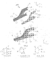
- a front structure for a motor vehicle is described in the form of a spar 10.
- the spar 10 is adapted to be mounted for part of its length under the floor P of a vehicle body. It extends substantially longitudinally along the longitudinal axis of the vehicle and it is expected to absorb the energy caused by frontal impacts and at two different heights of the body. Normally, it is possible to envisage a spar 10 per side of the compartment located in front of the deck.
- the spar 10 is formed of a first left part 12 and a second straight part 14 separated, both longitudinal and made of sheet metal, for example, by stamping. They can be realized in any material capable of forming a motor vehicle spar.
- FIGS. 2 to 3C illustrate the two parts 12, 14 after assembly in spar 10 which comprises a first 16, a second 18 and a third branch 20.
- the first branch 16 is the portion of the spar below the floor P at a height H ', substantially equal to the height of the floor and has a U-shaped section open on the upper edges 22, 24. Each edge 22, 24 is folded outward to present a connecting strip adapted to be secured along the length of the first branch 16 to the floor P of the body, for example by spot welding.
- the second branch 18 extends towards the front of the vehicle, and is substantially aligned with the axis of the first branch 16. It is disposed at the same height as the latter.
- the third branch 20 is above the second branch 18 and the space between these two branches 20, 18 forms a free zone.
- the two parts 12, 14 have flat outer faces. They are stamped from a flat sheet and the outer faces of the first 16 and second 18 branches are straight and continuous, forming a continuous lower edge 32.
- the upper free edge 22 of the first branch 16 and the upper free edge 36 of the second branch 18 are straight relative to each other.
- the junction zone 26 interrupts the upper free edges 22, 36. It is at this interruption of the upper free edges 22, 36 that the third branch 20 divides. Thanks to the continuity of the materials constituting the two parts 12, 14 in the length of the spar 10 and the fact that it has a branch constituted by the third branch 20, the spar 10 has a general shape of Y.
- the lower free edge 40 of its first and second sub-portions 28, 30 is folded perpendicular to the main surface of the first piece 12 from the junction 26 to the front edge 42.
- the upper free edge 44 of the first piece 12 is folded perpendicularly to the main surface of the first piece 12 over the entire length of the second sub-portion 30 so that these two folded portions are parallel and thus to form a U-shaped section channel.
- the second sub-portion 30 is closed between its upper edges 44 and lower 40 to form a closed section in the form of a quadrilateral when the two parts 12 and 14 are secured together.
- the spar 10 is formed of two parts 12, 14 separated stamped.
- the first sheet metal part 12 constitutes the left side of the spar 10.
- the first 16 and second branch 18 of this piece 12 has a shape of "L” formed by the folding of the sheet from the continuous lower free edge 43 towards the 10.
- the lower part of the "L” separates the two pieces 12, 14 to constitute the bottom of a channel and extends beyond the second piece 14 to form a connecting strip 46 with this second piece 14.
- the latter has a free lower edge 45 folded outwards to attach to the connecting strip 46, this is shown in FIG. 3A .
- the second branch 18 of the second piece 14 is folded along the length of its upper edge 48 towards the inside of the spar 10 so as to form a closed section in the form of a quadrilateral.
- the upper edge 48 is then folded vertically to form a connecting strip 50 with the upper edge 36 of the second branch 18 of the first part 12. With this connecting strip 50 the two parts 12 and 14 can be assembled for example by spot welding with reference to FIG. 3B.
- the third limb 20 of the first workpiece 12 is folded at its lower edge 40 from the curved portion 38 of the junction zone 26 along its length and along the length of the second subpart 30. This folding are then folded down the spar 10 to form a connecting strip 52 with the lower edge 40 of the third branch 20 of the second piece 14. With this connecting strip 52 the two parts 12 and 14 can assemble for example, by spot welding with reference to Figure 3C.
- the upper free edge 44 of the second sub-portion 30 of the third leg 20 of the second piece 12 is folded along the length of its upper edge 44 towards the inside of the spar 10. Then it is folded vertically to form a strip of connection 54 intended to be welded with the upper free edge 44 of the third branch 20 of the second part 14 so as to form a closed section in the form of a quadrilateral, with reference to FIG. 3C.
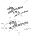
- the difference with the first embodiment lies in the fact that the two sides of the spar 100 are formed by a so-called “straight" part in the form of a shell 60 and a so-called “left” portion in the form of a flat sheet 62.
- Both 60, 62 comprise a first 64, a second 66 and third 68 branches of the same appearance as those 12, 14 of the spar 10 according to the first embodiment.
- the third branch 68 is above the second branch 66 and the space between these two branches 66, 68 forms a free zone.
- the shell 60 which is a first sheet metal part has a channel section open in the vertical plane and facing the sheet 62 which is a second sheet metal part.
- the shell 60 has outwardly facing connecting strips around the periphery of the second 66 and third 68 branches, including the junction 70 between the two 66 and 68 and also on the other edge of the second sub-portion 74. of the third leg 68, said second piece 62 in sheet metal remaining flat on the corresponding edges to form between the two sheet metal parts 60, 62, lower and upper connecting strips that can be welded, for example, by spot welding applied from outside said closed section.
- This The arrangement is visible in section for the second branch 66 with reference to FIG. 6B and for the third branch 68 with reference to FIG. 6C.
- the channel defined by the first branch 64 and the second branch 66 is continuous.
- the junction area 70 is formed by the departure of a channel to form the third branch 68 in a manner similar to the provision of the first sub-portion 28 of the third branch 20 of the first embodiment.
- the lower free edge 76 which extends over the entire length of the shell 60 and the other edge of its first leg 64 and the first sub-portion 72 of the third leg 68 exceeds the free edge of the sheet 62 to form a closed section with the sheet 62.
- the latter is folded outwardly of said closed section over a portion of the length of the corresponding edges to form between the two parts 60, 62, lower and upper connection strips may be welded for example, by spot welding applied from the outside of said closed section, with reference to FIG. 6A.
- the spar has branches of the same length, in fact, the length of the branches can vary depending on the type of vehicle.
- the two sheet metal parts may be according to the constraints imposed by each vehicle indifferently disposed towards the inside or the outside of the vehicle.
- the fixing between the two parts of the spar for each embodiment can be achieved by welding by point or by equivalent means such as gluing.
- the two pieces are fixed along the longitudinal axis over all or a significant part of the length and preferably also at the junction. Separating them in the event of a frontal impact is thus more difficult because the force forces are in the same longitudinal direction, for example in comparison with bolted systems where all the attachment means of the branches can be sheared.
- a spar is formed such that its deformation is predictable and with a reduced risk of separation of one or more branches compared to an arrangement where branches are separated and attached to a spar.
- the passage of forces towards the first branch and the floor during a frontal impact is easier through a continuous material between the three branches that through some existing assemblies branches, made, for example, by screwing as proposed in JP 2001-1310755 .
- the curved shape of the junction, in all the embodiments, between the second and the third branch significantly avoids a stress concentration, due to an impact, between the two branches to prevent them from separating. This advantage combines with the continuity between the branches for the best transmission of forces during a shock.
- the stamping could be made from two sheets of sheet metal with an automated attachment between them to obtain a reproducible quality and inexpensive. Their shape makes it possible to use a similar tool for both pieces.
- the shape of the spar according to the second embodiment that is to say closed over its entire length, has a stiffness even greater than the first embodiment.
- the closing sheet is simple to stamp and the attachment to the shell could be automated even simpler than the first embodiment, that is to say on one side of the spar.
Landscapes
- Engineering & Computer Science (AREA)
- Chemical & Material Sciences (AREA)
- Combustion & Propulsion (AREA)
- Transportation (AREA)
- Mechanical Engineering (AREA)
- Architecture (AREA)
- Structural Engineering (AREA)
- Body Structure For Vehicles (AREA)
Applications Claiming Priority (1)
| Application Number | Priority Date | Filing Date | Title |
|---|---|---|---|
| FR0651421A FR2900121B1 (fr) | 2006-04-21 | 2006-04-21 | Structure avant de vehicule automobile et un procede correspondant |
Publications (3)
| Publication Number | Publication Date |
|---|---|
| EP1847445A2 true EP1847445A2 (de) | 2007-10-24 |
| EP1847445A3 EP1847445A3 (de) | 2008-02-27 |
| EP1847445B1 EP1847445B1 (de) | 2009-07-15 |
Family
ID=37499699
Family Applications (1)
| Application Number | Title | Priority Date | Filing Date |
|---|---|---|---|
| EP20070300952 Not-in-force EP1847445B1 (de) | 2006-04-21 | 2007-04-16 | Struktur vor einem Kraftfahrzeug und ein entsprechendes Verfahren |
Country Status (3)
| Country | Link |
|---|---|
| EP (1) | EP1847445B1 (de) |
| DE (1) | DE602007001552D1 (de) |
| FR (1) | FR2900121B1 (de) |
Cited By (1)
| Publication number | Priority date | Publication date | Assignee | Title |
|---|---|---|---|---|
| EP2080691A1 (de) | 2008-01-21 | 2009-07-22 | Peugeot Citroën Automobiles S.A. | Aussteifung der Rahmenkonstruktion eines Kraftfahrzeugs, Rahmenkonstruktion und Befestigungsverfahren einer solchen Aussteifung auf der Rahmenkonstruktion |
Citations (1)
| Publication number | Priority date | Publication date | Assignee | Title |
|---|---|---|---|---|
| JP2001131755A (ja) | 1996-09-10 | 2001-05-15 | Hitachi Maxell Ltd | プラズマcvd装置 |
Family Cites Families (6)
| Publication number | Priority date | Publication date | Assignee | Title |
|---|---|---|---|---|
| JPS58126262A (ja) * | 1982-01-18 | 1983-07-27 | Mazda Motor Corp | キヤブオ−バ型自動車の下部車体構造 |
| JPS58188760A (ja) * | 1982-04-26 | 1983-11-04 | Mazda Motor Corp | 自動車の車体前部の構造 |
| DE3522447C2 (de) * | 1985-01-24 | 1995-01-05 | Volkswagen Ag | Vorderwagen für ein Kraftfahrzeug |
| FR2615156B1 (fr) * | 1987-05-13 | 1989-08-18 | Peugeot Aciers Et Outillage | Structure modulaire pour vehicule et son application a l'assemblage automatique de celui-ci |
| DE19727615A1 (de) * | 1996-08-14 | 1999-02-04 | Opel Adam Ag | Karosserievorderbau für ein Kraftfahrzeug |
| JP4558137B2 (ja) | 2000-04-28 | 2010-10-06 | 富士重工業株式会社 | 車両の車体前部構造 |
-
2006
- 2006-04-21 FR FR0651421A patent/FR2900121B1/fr not_active Expired - Fee Related
-
2007
- 2007-04-16 EP EP20070300952 patent/EP1847445B1/de not_active Not-in-force
- 2007-04-16 DE DE200760001552 patent/DE602007001552D1/de active Active
Patent Citations (1)
| Publication number | Priority date | Publication date | Assignee | Title |
|---|---|---|---|---|
| JP2001131755A (ja) | 1996-09-10 | 2001-05-15 | Hitachi Maxell Ltd | プラズマcvd装置 |
Cited By (2)
| Publication number | Priority date | Publication date | Assignee | Title |
|---|---|---|---|---|
| EP2080691A1 (de) | 2008-01-21 | 2009-07-22 | Peugeot Citroën Automobiles S.A. | Aussteifung der Rahmenkonstruktion eines Kraftfahrzeugs, Rahmenkonstruktion und Befestigungsverfahren einer solchen Aussteifung auf der Rahmenkonstruktion |
| FR2926527A1 (fr) * | 2008-01-21 | 2009-07-24 | Peugeot Citroen Automobiles Sa | Raidisseur d'ossature de vehicule automobile, ossature et procede de fixation d'un tel raidisseur sur une ossature |
Also Published As
| Publication number | Publication date |
|---|---|
| FR2900121B1 (fr) | 2008-09-19 |
| DE602007001552D1 (de) | 2009-08-27 |
| FR2900121A1 (fr) | 2007-10-26 |
| EP1847445B1 (de) | 2009-07-15 |
| EP1847445A3 (de) | 2008-02-27 |
Similar Documents
| Publication | Publication Date | Title |
|---|---|---|
| FR2791628A1 (fr) | Combinaison d'une peau de pare-chocs et d'un carenage sous moteur pour vehicule | |
| FR3069517A1 (fr) | Traverse de planche de bord a jambe de force effacee pour vehicule automobile | |
| EP1884416B1 (de) | Blockrahmen vor Kraftfahrzeugen | |
| EP2744698B1 (de) | Kraftfahrzeugkarosserie mit einer versteifungsvorrichtung | |
| EP4294706B1 (de) | Untergestellstruktur für ein kraftfahrzeug mit einem seitlichen verstärkungsteil | |
| EP4511277B1 (de) | Kraftfahrzeug mit einem seitenglied mit einem verstärkungsteil | |
| EP1847445B1 (de) | Struktur vor einem Kraftfahrzeug und ein entsprechendes Verfahren | |
| FR3094326A1 (fr) | Structure arrière de caisse de véhicule automobile comportant des platines de renfort fixées sur les longeronnets avant | |
| FR3022520A1 (fr) | Plancher de vehicule automobile avec podium de renfort composite | |
| EP1693283B1 (de) | Vorderbau für ein Kraftfahrzeug | |
| FR2977222A3 (fr) | Renfort d'ensemble de jupe arriere | |
| EP3386807A1 (de) | Stossfänger für ein kraftfahrzeug mit einem querträger und stossdämpfer | |
| WO2024089341A1 (fr) | Module d'entrée d'air pilotée pour face avant de véhicule automobile, face avant de véhicule automobile comportant un tel module et véhicule automobile comportant une telle face avant | |
| FR2912371A1 (fr) | Dispositif de bloc avant de vehicule automobile | |
| EP2176093B1 (de) | Stossfängerschild | |
| WO2025032290A1 (fr) | Plancher de vehicule equipe d'un dispositif anti deversement des traverses d'assise | |
| EP3199409B1 (de) | Formelement eines belüftungsgitters für die frontseite eines kraftfahrzeugs | |
| FR3072070B1 (fr) | Partie arriere d’un vehicule adaptee pour amortir un choc arriere qui comporte un puits dans lequel est positionnee une roue de secours | |
| FR3018231A1 (fr) | Traverse d’assise renforcee pour vehicule automobile | |
| FR2882327A1 (fr) | Structure avant de vehicule automobile | |
| FR3160141A1 (fr) | Siège à dossiers rabattables transmettant les efforts en cas de choc latéral, pour un véhicule terrestre | |
| WO2023180645A1 (fr) | Structure de montage d'une gâche d'un capot | |
| FR3017360A1 (fr) | Longeron automobile a raidisseur oblique pour deversement programme en choc mur | |
| FR2924667A1 (fr) | Dispositif anti-echappement d'un ouvrant lateral de vehicule automobile en cas de choc frontal. | |
| FR2982814A1 (fr) | Systeme de resistance aux chocs comprenant une piece de renfort. |
Legal Events
| Date | Code | Title | Description |
|---|---|---|---|
| PUAI | Public reference made under article 153(3) epc to a published international application that has entered the european phase |
Free format text: ORIGINAL CODE: 0009012 |
|
| AK | Designated contracting states |
Kind code of ref document: A2 Designated state(s): AT BE BG CH CY CZ DE DK EE ES FI FR GB GR HU IE IS IT LI LT LU LV MC MT NL PL PT RO SE SI SK TR |
|
| AX | Request for extension of the european patent |
Extension state: AL BA HR MK YU |
|
| PUAL | Search report despatched |
Free format text: ORIGINAL CODE: 0009013 |
|
| AK | Designated contracting states |
Kind code of ref document: A3 Designated state(s): AT BE BG CH CY CZ DE DK EE ES FI FR GB GR HU IE IS IT LI LT LU LV MC MT NL PL PT RO SE SI SK TR |
|
| AX | Request for extension of the european patent |
Extension state: AL BA HR MK YU |
|
| 17P | Request for examination filed |
Effective date: 20080625 |
|
| 17Q | First examination report despatched |
Effective date: 20080812 |
|
| AKX | Designation fees paid |
Designated state(s): AT BE BG CH CY CZ DE DK EE ES FI FR GB GR HU IE IS IT LI LT LU LV MC MT NL PL PT RO SE SI SK TR |
|
| GRAP | Despatch of communication of intention to grant a patent |
Free format text: ORIGINAL CODE: EPIDOSNIGR1 |
|
| GRAS | Grant fee paid |
Free format text: ORIGINAL CODE: EPIDOSNIGR3 |
|
| GRAA | (expected) grant |
Free format text: ORIGINAL CODE: 0009210 |
|
| AK | Designated contracting states |
Kind code of ref document: B1 Designated state(s): AT BE BG CH CY CZ DE DK EE ES FI FR GB GR HU IE IS IT LI LT LU LV MC MT NL PL PT RO SE SI SK TR |
|
| REG | Reference to a national code |
Ref country code: CH Ref legal event code: EP Ref country code: GB Ref legal event code: FG4D Free format text: NOT ENGLISH |
|
| REG | Reference to a national code |
Ref country code: IE Ref legal event code: FG4D |
|
| REF | Corresponds to: |
Ref document number: 602007001552 Country of ref document: DE Date of ref document: 20090827 Kind code of ref document: P |
|
| NLV1 | Nl: lapsed or annulled due to failure to fulfill the requirements of art. 29p and 29m of the patents act | ||
| PG25 | Lapsed in a contracting state [announced via postgrant information from national office to epo] |
Ref country code: LT Free format text: LAPSE BECAUSE OF FAILURE TO SUBMIT A TRANSLATION OF THE DESCRIPTION OR TO PAY THE FEE WITHIN THE PRESCRIBED TIME-LIMIT Effective date: 20090715 Ref country code: ES Free format text: LAPSE BECAUSE OF FAILURE TO SUBMIT A TRANSLATION OF THE DESCRIPTION OR TO PAY THE FEE WITHIN THE PRESCRIBED TIME-LIMIT Effective date: 20091026 Ref country code: IS Free format text: LAPSE BECAUSE OF FAILURE TO SUBMIT A TRANSLATION OF THE DESCRIPTION OR TO PAY THE FEE WITHIN THE PRESCRIBED TIME-LIMIT Effective date: 20091115 Ref country code: SE Free format text: LAPSE BECAUSE OF FAILURE TO SUBMIT A TRANSLATION OF THE DESCRIPTION OR TO PAY THE FEE WITHIN THE PRESCRIBED TIME-LIMIT Effective date: 20090715 Ref country code: AT Free format text: LAPSE BECAUSE OF FAILURE TO SUBMIT A TRANSLATION OF THE DESCRIPTION OR TO PAY THE FEE WITHIN THE PRESCRIBED TIME-LIMIT Effective date: 20090715 Ref country code: FI Free format text: LAPSE BECAUSE OF FAILURE TO SUBMIT A TRANSLATION OF THE DESCRIPTION OR TO PAY THE FEE WITHIN THE PRESCRIBED TIME-LIMIT Effective date: 20090715 |
|
| REG | Reference to a national code |
Ref country code: IE Ref legal event code: FD4D |
|
| PG25 | Lapsed in a contracting state [announced via postgrant information from national office to epo] |
Ref country code: NL Free format text: LAPSE BECAUSE OF FAILURE TO SUBMIT A TRANSLATION OF THE DESCRIPTION OR TO PAY THE FEE WITHIN THE PRESCRIBED TIME-LIMIT Effective date: 20090715 Ref country code: PL Free format text: LAPSE BECAUSE OF FAILURE TO SUBMIT A TRANSLATION OF THE DESCRIPTION OR TO PAY THE FEE WITHIN THE PRESCRIBED TIME-LIMIT Effective date: 20090715 Ref country code: LV Free format text: LAPSE BECAUSE OF FAILURE TO SUBMIT A TRANSLATION OF THE DESCRIPTION OR TO PAY THE FEE WITHIN THE PRESCRIBED TIME-LIMIT Effective date: 20090715 Ref country code: SI Free format text: LAPSE BECAUSE OF FAILURE TO SUBMIT A TRANSLATION OF THE DESCRIPTION OR TO PAY THE FEE WITHIN THE PRESCRIBED TIME-LIMIT Effective date: 20090715 |
|
| PG25 | Lapsed in a contracting state [announced via postgrant information from national office to epo] |
Ref country code: BG Free format text: LAPSE BECAUSE OF FAILURE TO SUBMIT A TRANSLATION OF THE DESCRIPTION OR TO PAY THE FEE WITHIN THE PRESCRIBED TIME-LIMIT Effective date: 20091015 Ref country code: PT Free format text: LAPSE BECAUSE OF FAILURE TO SUBMIT A TRANSLATION OF THE DESCRIPTION OR TO PAY THE FEE WITHIN THE PRESCRIBED TIME-LIMIT Effective date: 20091115 |
|
| PG25 | Lapsed in a contracting state [announced via postgrant information from national office to epo] |
Ref country code: IE Free format text: LAPSE BECAUSE OF FAILURE TO SUBMIT A TRANSLATION OF THE DESCRIPTION OR TO PAY THE FEE WITHIN THE PRESCRIBED TIME-LIMIT Effective date: 20090715 Ref country code: RO Free format text: LAPSE BECAUSE OF FAILURE TO SUBMIT A TRANSLATION OF THE DESCRIPTION OR TO PAY THE FEE WITHIN THE PRESCRIBED TIME-LIMIT Effective date: 20090715 Ref country code: EE Free format text: LAPSE BECAUSE OF FAILURE TO SUBMIT A TRANSLATION OF THE DESCRIPTION OR TO PAY THE FEE WITHIN THE PRESCRIBED TIME-LIMIT Effective date: 20090715 Ref country code: CZ Free format text: LAPSE BECAUSE OF FAILURE TO SUBMIT A TRANSLATION OF THE DESCRIPTION OR TO PAY THE FEE WITHIN THE PRESCRIBED TIME-LIMIT Effective date: 20090715 Ref country code: DK Free format text: LAPSE BECAUSE OF FAILURE TO SUBMIT A TRANSLATION OF THE DESCRIPTION OR TO PAY THE FEE WITHIN THE PRESCRIBED TIME-LIMIT Effective date: 20090715 |
|
| PLBE | No opposition filed within time limit |
Free format text: ORIGINAL CODE: 0009261 |
|
| STAA | Information on the status of an ep patent application or granted ep patent |
Free format text: STATUS: NO OPPOSITION FILED WITHIN TIME LIMIT |
|
| PG25 | Lapsed in a contracting state [announced via postgrant information from national office to epo] |
Ref country code: SK Free format text: LAPSE BECAUSE OF FAILURE TO SUBMIT A TRANSLATION OF THE DESCRIPTION OR TO PAY THE FEE WITHIN THE PRESCRIBED TIME-LIMIT Effective date: 20090715 |
|
| 26N | No opposition filed |
Effective date: 20100416 |
|
| PG25 | Lapsed in a contracting state [announced via postgrant information from national office to epo] |
Ref country code: GR Free format text: LAPSE BECAUSE OF FAILURE TO SUBMIT A TRANSLATION OF THE DESCRIPTION OR TO PAY THE FEE WITHIN THE PRESCRIBED TIME-LIMIT Effective date: 20091016 |
|
| BERE | Be: lapsed |
Owner name: RENAULT S.A.S. Effective date: 20100430 |
|
| PG25 | Lapsed in a contracting state [announced via postgrant information from national office to epo] |
Ref country code: MC Free format text: LAPSE BECAUSE OF NON-PAYMENT OF DUE FEES Effective date: 20100430 |
|
| PG25 | Lapsed in a contracting state [announced via postgrant information from national office to epo] |
Ref country code: IT Free format text: LAPSE BECAUSE OF FAILURE TO SUBMIT A TRANSLATION OF THE DESCRIPTION OR TO PAY THE FEE WITHIN THE PRESCRIBED TIME-LIMIT Effective date: 20090715 Ref country code: BE Free format text: LAPSE BECAUSE OF NON-PAYMENT OF DUE FEES Effective date: 20100430 |
|
| PG25 | Lapsed in a contracting state [announced via postgrant information from national office to epo] |
Ref country code: MT Free format text: LAPSE BECAUSE OF FAILURE TO SUBMIT A TRANSLATION OF THE DESCRIPTION OR TO PAY THE FEE WITHIN THE PRESCRIBED TIME-LIMIT Effective date: 20090715 |
|
| REG | Reference to a national code |
Ref country code: CH Ref legal event code: PL |
|
| PG25 | Lapsed in a contracting state [announced via postgrant information from national office to epo] |
Ref country code: CH Free format text: LAPSE BECAUSE OF NON-PAYMENT OF DUE FEES Effective date: 20110430 Ref country code: LI Free format text: LAPSE BECAUSE OF NON-PAYMENT OF DUE FEES Effective date: 20110430 |
|
| PG25 | Lapsed in a contracting state [announced via postgrant information from national office to epo] |
Ref country code: CY Free format text: LAPSE BECAUSE OF FAILURE TO SUBMIT A TRANSLATION OF THE DESCRIPTION OR TO PAY THE FEE WITHIN THE PRESCRIBED TIME-LIMIT Effective date: 20090715 |
|
| PG25 | Lapsed in a contracting state [announced via postgrant information from national office to epo] |
Ref country code: LU Free format text: LAPSE BECAUSE OF NON-PAYMENT OF DUE FEES Effective date: 20100416 Ref country code: HU Free format text: LAPSE BECAUSE OF FAILURE TO SUBMIT A TRANSLATION OF THE DESCRIPTION OR TO PAY THE FEE WITHIN THE PRESCRIBED TIME-LIMIT Effective date: 20100116 |
|
| PG25 | Lapsed in a contracting state [announced via postgrant information from national office to epo] |
Ref country code: TR Free format text: LAPSE BECAUSE OF FAILURE TO SUBMIT A TRANSLATION OF THE DESCRIPTION OR TO PAY THE FEE WITHIN THE PRESCRIBED TIME-LIMIT Effective date: 20090715 |
|
| REG | Reference to a national code |
Ref country code: FR Ref legal event code: PLFP Year of fee payment: 9 |
|
| REG | Reference to a national code |
Ref country code: FR Ref legal event code: PLFP Year of fee payment: 10 |
|
| REG | Reference to a national code |
Ref country code: FR Ref legal event code: PLFP Year of fee payment: 11 |
|
| REG | Reference to a national code |
Ref country code: FR Ref legal event code: PLFP Year of fee payment: 12 |
|
| PGFP | Annual fee paid to national office [announced via postgrant information from national office to epo] |
Ref country code: GB Payment date: 20220420 Year of fee payment: 16 Ref country code: FR Payment date: 20220421 Year of fee payment: 16 Ref country code: DE Payment date: 20220420 Year of fee payment: 16 |
|
| REG | Reference to a national code |
Ref country code: DE Ref legal event code: R119 Ref document number: 602007001552 Country of ref document: DE |
|
| GBPC | Gb: european patent ceased through non-payment of renewal fee |
Effective date: 20230416 |
|
| PG25 | Lapsed in a contracting state [announced via postgrant information from national office to epo] |
Ref country code: GB Free format text: LAPSE BECAUSE OF NON-PAYMENT OF DUE FEES Effective date: 20230416 |
|
| PG25 | Lapsed in a contracting state [announced via postgrant information from national office to epo] |
Ref country code: GB Free format text: LAPSE BECAUSE OF NON-PAYMENT OF DUE FEES Effective date: 20230416 Ref country code: FR Free format text: LAPSE BECAUSE OF NON-PAYMENT OF DUE FEES Effective date: 20230430 Ref country code: DE Free format text: LAPSE BECAUSE OF NON-PAYMENT OF DUE FEES Effective date: 20231103 |