EP1847677A2 - Rollladenkasten für Rollläden, der zur Montage an einer Zarge eines Fensterrahmens konzipiert ist - Google Patents
Rollladenkasten für Rollläden, der zur Montage an einer Zarge eines Fensterrahmens konzipiert ist Download PDFInfo
- Publication number
- EP1847677A2 EP1847677A2 EP07008088A EP07008088A EP1847677A2 EP 1847677 A2 EP1847677 A2 EP 1847677A2 EP 07008088 A EP07008088 A EP 07008088A EP 07008088 A EP07008088 A EP 07008088A EP 1847677 A2 EP1847677 A2 EP 1847677A2
- Authority
- EP
- European Patent Office
- Prior art keywords
- frame
- box
- tunnel
- wall
- tunnel box
- Prior art date
- Legal status (The legal status is an assumption and is not a legal conclusion. Google has not performed a legal analysis and makes no representation as to the accuracy of the status listed.)
- Withdrawn
Links
Images



Classifications
-
- E—FIXED CONSTRUCTIONS
- E06—DOORS, WINDOWS, SHUTTERS, OR ROLLER BLINDS IN GENERAL; LADDERS
- E06B—FIXED OR MOVABLE CLOSURES FOR OPENINGS IN BUILDINGS, VEHICLES, FENCES OR LIKE ENCLOSURES IN GENERAL, e.g. DOORS, WINDOWS, BLINDS, GATES
- E06B9/00—Screening or protective devices for wall or similar openings, with or without operating or securing mechanisms; Closures of similar construction
- E06B9/02—Shutters, movable grilles, or other safety closing devices, e.g. against burglary
- E06B9/08—Roll-type closures
- E06B9/11—Roller shutters
- E06B9/17—Parts or details of roller shutters, e.g. suspension devices, shutter boxes, wicket doors, ventilation openings
- E06B9/17061—Connection of the box to the guides
-
- E—FIXED CONSTRUCTIONS
- E06—DOORS, WINDOWS, SHUTTERS, OR ROLLER BLINDS IN GENERAL; LADDERS
- E06B—FIXED OR MOVABLE CLOSURES FOR OPENINGS IN BUILDINGS, VEHICLES, FENCES OR LIKE ENCLOSURES IN GENERAL, e.g. DOORS, WINDOWS, BLINDS, GATES
- E06B9/00—Screening or protective devices for wall or similar openings, with or without operating or securing mechanisms; Closures of similar construction
- E06B9/02—Shutters, movable grilles, or other safety closing devices, e.g. against burglary
- E06B9/08—Roll-type closures
- E06B9/11—Roller shutters
- E06B9/17—Parts or details of roller shutters, e.g. suspension devices, shutter boxes, wicket doors, ventilation openings
- E06B9/17007—Shutter boxes; Details or component parts thereof
Definitions
- the present invention relates to a tunnel box for roller shutter intended to rest on the upper cross member of a frame provided with slides, the tunnel box comprising a box closed at its lateral ends by a pair of cheeks, the latter being respectively provided two anchors provided to be mounted behind the scenes.
- a tunnel box for roller shutter is an accessory that is placed above an embrasure made in a wall to receive a window or a door in order to conceal, by means of an apron, at least partially said embrasure .
- the tunnel box thus comprises a box consisting of an inverted U section section, closed at its free ends by two cheeks between which is held a drive drum around which can roll or unfold the deck.
- the box can be integrated in the construction of the masonry, above the embrasure or be placed later.
- the invention is concerned with this latter configuration.
- a box and generally a tunnel box after the construction of the wall, it can be fixed on a frame of a frame that is then secured in the doorway.
- the frame includes in particular two vertical uprights joined at their ends by a lower cross and an upper cross. Two slides are contiguous to the vertical uprights, at the back of the frame, to allow the sliding of the ends of the constituent blades of the deck.
- the tunnel box is usually provided on its cheeks with two legs as shown in the patent application.
- FR-A-2,343,117 These legs, which project downward, are planned to fit into two scenes.
- the installation of the tunnel box in the wings is achieved by a vertical movement of the latter so that the legs can be embedded in the wings.
- the tunnel box then rests on the upper cross member of the frame.
- the assembly that is to say the frame provided with its tunnel box, is then mounted in the doorway. For this, and taking into account the mass of the assembly, the lower cross member of the frame is placed on the lower wall of the recess and the assembly is tilted in said opening.
- the fixation of the tunnel box on the frame is not always satisfactory because although held by its legs fixed behind the scenes, the tunnel-box is mounted cantilevered at the back of the giving so that it remains hidden as much what can be done at the end of his pose. Moreover, because of its cantilevered mounting, it protrudes from the rear part of the frame so that it is necessary to provide a greater height of the doorway in order to accommodate the frame and the tunnel box in that frame. this.
- the residual space between the upper wall of the embrasure and the wall of the box of the tunnel box, of relatively large height, must be filled by a binder to fix the tunnel box also with the wall. A thinner binder thickness would be better to obtain a good adhesion of the box against the upper wall of the embrasure.
- the object of the invention is therefore to provide a tunnel box which can provide a solution to these various problems.
- a shutter tunnel box for assembly to a frame of a frame, the frame being capable of being embedded in an embrasure, the frame being provided with slides, the tunnel box comprising a box closed at its lateral ends by a pair of cheeks, the latter being provided respectively with two anchors provided to be mounted behind the scenes.
- the anchoring tabs are articulately assembled on the cheeks.
- the tunnel box can be tilted during the mounting of the anchoring tabs in the slides, which has the advantage of being able to facilitate its assembly with the upper cross member of the frame by means of an additional fastening means. to improve its fixation or facilitate the mounting of the frame provided with its tunnel box in an embrasure.
- the frame comprises an upper rail, the box comprising a pair of branches joined by an arch wall, a tongue being fixed under a branch so as to cooperate with a housing provided on the upper rail the frame to fix said tunnel box on said frame.
- the tunnel box is also assembled with the upper cross member of the frame.
- the housing consists of a location between a folded blade and the upper cross member, the folded blade comprising a first branch attached to said upper cross member, an intermediate branch inclined relative to the first and which extends as well as a third branch which extends the intermediate branch parallel to the first, the projecting portion of the tongue being recessed between the third branch of the blade and the upper cross.
- the box comprises a vault wall, the latter being provided with a stop adapted to cooperate with the inner wall of a wall flanking an embrasure.
- the abutment consists of a section of triangular section.
- the slides are fixed against the vertical uprights of the frame and each slide is provided with a housing adapted to receive the projecting portion of an anchoring tab.
- each anchor tab is assembled outside a corresponding cheek via a hinge.
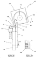
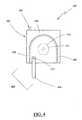
- the tunnel box 100 shown in FIG. 1 is intended to be placed in the upper part of an embrasure made in a wall to at least partially obscure, and through an apron, said embrasure.
- the tunnel box 100 thus comprises a box 200 closed at its lateral ends by a pair of cheeks 300, a fastening means 400 of the tunnel box with, on the one hand, the upper cross member of a frame of a frame and on the other hand, a backstage game.
- the box 200 consists of a profile, for example a profile made of polystyrene, inverted U-shaped section. It thus comprises a first branch 202 and a second branch 204 joined by an edge by an arch wall 206.
- the two cheeks 300 respectively close the two lateral ends of the box 200 in order to be able to hold, by its two free ends, the axis of a winding drum 310 around which is wrapped the concealment apron of the doorway.
- the fastening means 400 comprises a pair of anchoring tabs 410 respectively mounted in an articulated manner on the two cheeks 300, as well as a tongue 420.
- the two anchoring lugs 410 are thus assembled by one of their ends and by means of articulations 412 on the two cheeks 300. They are preferably, and as it appears in this FIG. 1, mounted outside the cheeks 300.
- the tongue 420 is advantageously constituted by a metal blade fixed under a branch and here the first branch 202 of the box 200.
- the tongue 420 projects at the rear of the first branch 202.
- FIG. 2a there is shown a tunnel box 100 being mounted on a pair of slides Co and on the upper rail Ts of the frame D of a frame.
- the assembly thus formed can be mounted in a single operation in the doorway, which reduces the exposure time of the assembly.
- the fixing means 400 further comprises a housing 430 provided on the upper cross member Ts of the frame D and which is able to receive the protruding portion of the tongue 420.
- the housing 430 is constituted here of a location between a folded blade and the upper crossbar Ts on which it is fixed.
- the folded blade thus comprises a first branch attached to the upper cross member Ts, an intermediate branch inclined relative to the first and which extends, and a third branch which extends the intermediate branch parallel to the first.
- the protruding portion of the tongue 420 can thus be embedded between the third branch of the blade and the upper cross member Ts.
- the two wings Co are contiguous to the uprights Mv of the frame D. Only one of these slides is visible in this FIG. They are designed to allow the sliding of the rolled apron on the winding drum 310 guiding the ends of the blades that constitute it.
- Each slide Co is provided in FIG. 2b of a housing Lo adapted to receive the free end of an anchor lug.
- the housing Lo is arranged in the bottom of the slide Co so that the apron can slide between the free branches of said slides.
- tunnel box 100 The mounting of tunnel box 100 is preferably done in the factory and in the following manner.
- the anchoring lugs 410 are lowered in a combined movement in the free ends of the wings Co as shown by the arrow F1 and the tunnel box 100 is turned according to the arrow F2 so that the tongue 420 can be held in the housing 430. It can thus deliver the window or door equipped with its tunnel box.
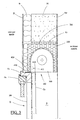
- the assembly comprising the tunnel box 100, the frame D of the frame and the slides Co is installed according to the rules of art in an embrasure E made in a wall M.
- the finishing is then carried out.
- a binder Li such as cement is introduced between the wall M and the arch wall 206 of the box 200 to also secure it to the wall M.
- a protective coating Ep is applied to the wall of the box facing outwards. .
- Plaster Pl is still deposited in the form of plates against the inner wall of the wall M over an insulator Is and so as to mask the casing 200.
- the tunnel box of the invention can thus be simply and effectively fastened to the frame of a frame. Its mounting on the frame is advantageously done in the factory
- the tunnel trunk 100 is always provided with a fastening means 400 'comprising a pair of anchoring lugs 410 respectively hingedly mounted on the two cheeks 300, but it no longer has a tongue.
- the casing 200 is provided on its arch wall 206 with a stop 450. This is constituted in this FIG. a section of fixed triangular section, preferably by gluing on said arch wall 206.
- tunnel box 100 is no longer factory mounted but is mounted during the installation of the window in the recess.
- the anchor tabs 410 of the tunnel box 100 were mounted in the wings.
- the assembly comprising the tunnel box 100, the frame D of the frame as well as the slides CC is being placed in the recess E.
- the foot of the frame D on the wall bottom of the recess E we rock the assembly following an arc materialized by the arrow F3 to embed it in said embrasure.
- the tunnel box 100 is tilted slightly forwards around its hinges 412 during this operation so that its most protruding part can pass under the upper wall Ps of the embrasure E. This tilting is materialized by the arrow F4.
- the assembly is mounted in the recess E.
- the box 200 has been abutted against the inner wall of the wall M, via its stop 450, for the straighten.
- Stop 450 is positioned so that the branch intended to be turned towards the outside of the wall M, here the second branch 204, is placed substantially in line with the outer wall of the wall M.
- a binder Li such as cement is introduced between the wall M and the arch wall 206 of the box 200 to also secure it to the wall M.
- a protective coating Ep is applied to the wall of the box facing outwards.
- Plaster Pl is still deposited in the form of plates against the inner wall of the wall M over an insulator Is so as to mask the casing 200.
- the space between the upper wall of the wall M and the upper wall of the box 200 can be reduced so that the Thickness e of the binder layer Li is lower than in an assembly incorporating a tunnel box of the prior art, thus providing better fixing of the box with the wall M.
- the mounting of the tunnel box on the frame is advantageously carried out during the installation thereof in the recess.
Landscapes
- Engineering & Computer Science (AREA)
- Structural Engineering (AREA)
- Architecture (AREA)
- Civil Engineering (AREA)
- Housing For Livestock And Birds (AREA)
- Operating, Guiding And Securing Of Roll- Type Closing Members (AREA)
- Blinds (AREA)
Applications Claiming Priority (1)
| Application Number | Priority Date | Filing Date | Title |
|---|---|---|---|
| FR0603536A FR2900189B1 (fr) | 2006-04-20 | 2006-04-20 | Coffre-tunnel de volet roulant destine a etre assemble a un dormant d'une huisserie |
Publications (2)
| Publication Number | Publication Date |
|---|---|
| EP1847677A2 true EP1847677A2 (de) | 2007-10-24 |
| EP1847677A3 EP1847677A3 (de) | 2007-12-26 |
Family
ID=37546942
Family Applications (1)
| Application Number | Title | Priority Date | Filing Date |
|---|---|---|---|
| EP07008088A Withdrawn EP1847677A3 (de) | 2006-04-20 | 2007-04-20 | Rollladenkasten für Rollläden, der zur Montage an einer Zarge eines Fensterrahmens konzipiert ist |
Country Status (2)
| Country | Link |
|---|---|
| EP (1) | EP1847677A3 (de) |
| FR (1) | FR2900189B1 (de) |
Cited By (2)
| Publication number | Priority date | Publication date | Assignee | Title |
|---|---|---|---|---|
| DE102016002848A1 (de) * | 2016-03-10 | 2017-09-14 | Roma Kg | Gebäudeöffnungsverschattungsvorrichtung sowie Befestigungsanordnung zur Befestigung deren Wickelwellenkastens an einem Fenster- oder Türrahmen |
| EP4481152A1 (de) * | 2023-06-19 | 2024-12-25 | VKR Holding A/S | Innendachfensterabdeckungsanordnung mit einem verbindungsarm und verfahren zur installation solch einer abschirmungsanordnung |
Family Cites Families (4)
| Publication number | Priority date | Publication date | Assignee | Title |
|---|---|---|---|---|
| DE2345891A1 (de) * | 1973-09-12 | 1975-04-10 | Rau Dieter | Rolladen-fuehrungsvorrichtung |
| DE4019773A1 (de) * | 1990-06-21 | 1992-01-02 | Armin Besler | Zusammenfassung eines an einem blendrahmen ansetzbaren rolladenkastens mit dem blendrahmen |
| FR2809762B1 (fr) * | 2000-05-31 | 2003-03-14 | Simbac S P A | Procede d'assemblage d'un bloc baie et d'un caisson, ensemble forme d'un bloc baie et d'un caisson et console d'extremite d'un tel caisson |
| DE10139426A1 (de) * | 2001-08-17 | 2003-02-27 | Helmut Lehr Rolladenkasten | Rolladenkasten |
-
2006
- 2006-04-20 FR FR0603536A patent/FR2900189B1/fr not_active Expired - Lifetime
-
2007
- 2007-04-20 EP EP07008088A patent/EP1847677A3/de not_active Withdrawn
Cited By (3)
| Publication number | Priority date | Publication date | Assignee | Title |
|---|---|---|---|---|
| DE102016002848A1 (de) * | 2016-03-10 | 2017-09-14 | Roma Kg | Gebäudeöffnungsverschattungsvorrichtung sowie Befestigungsanordnung zur Befestigung deren Wickelwellenkastens an einem Fenster- oder Türrahmen |
| DE102016002848B4 (de) * | 2016-03-10 | 2020-04-16 | Roma Kg | Gebäudeöffnungsverschattungsvorrichtung sowie Befestigungsanordnung zur Befestigung deren Wickelwellenkastens an einem Fenster- oder Türrahmen |
| EP4481152A1 (de) * | 2023-06-19 | 2024-12-25 | VKR Holding A/S | Innendachfensterabdeckungsanordnung mit einem verbindungsarm und verfahren zur installation solch einer abschirmungsanordnung |
Also Published As
| Publication number | Publication date |
|---|---|
| FR2900189B1 (fr) | 2008-06-13 |
| EP1847677A3 (de) | 2007-12-26 |
| FR2900189A1 (fr) | 2007-10-26 |
Similar Documents
| Publication | Publication Date | Title |
|---|---|---|
| EP1847677A2 (de) | Rollladenkasten für Rollläden, der zur Montage an einer Zarge eines Fensterrahmens konzipiert ist | |
| EP1803887B1 (de) | Kasten mit Rolladen und Fensterrahmenblock | |
| EP1336716B1 (de) | Befestigungsvorrichtung für einen Verschlussdeckel auf einem Rolladenkasten | |
| FR2992017A1 (fr) | Coffre-tunnel incorporant une patte de fixation entre un linteau et le dormant d'une menuiserie | |
| EP0851089B1 (de) | Rolladenkasten und Fensterzusammenbau | |
| EP1045106B1 (de) | Verfahren zum Anbringen eines Rahmenbauteils mit Rolladenkasten | |
| EP2942472B1 (de) | Verschlussvorrichtung vom typ jalousie, rollladen oder ähnliches, insbesondere für ein dachfenster | |
| EP2366863B1 (de) | Verschalungstunnel, der eine Armierung zur Verstärkung seiner Struktur beinhaltet | |
| EP1022427B1 (de) | Tür- oder Fenster- und Rolladenbaueinheit oder dergleichen | |
| FR2969203A1 (fr) | Dispositif de mise en place et de maintien d'un caisson d'un systeme d'occultation, caisson, coulisse et procede de montage correspondants. | |
| EP2108777B1 (de) | Rollladenkasten | |
| EP0841461B1 (de) | Befestigungsvorrichtung für Schiebepaneel | |
| FR2974592A1 (fr) | Equipement de baie et coffre a volet roulant renforce faisant partie de cet equipement | |
| FR2873400A1 (fr) | Ensemble de lames articulees, tablier de volet roulant et volet roulant ainsi forme | |
| EP2325434B1 (de) | Rollladenkasten, der mit einer Verbindungsschiene für eine Zarge ausgestattet ist | |
| EP2947257B1 (de) | Rollladenkasten, der mit einer aufnahmebohrung für ein verbindungsmittel zwischen einem sturz und einer zarge einer tür-/fenstereinfassung ausgestattet ist | |
| EP2080868B1 (de) | Schiebetür- oder Fensterflügel, insbesondere vom Typ Rollladen | |
| EP3623564B1 (de) | Schliess- und verdunkelungsvorrichtung mit schutzgitter und einbruchsicherungssystem | |
| FR2877985A1 (fr) | Joue pour coffre de volet et coffre comprenant au moins deux joues | |
| FR2803329A1 (fr) | Dispositif obturateur pour coffre-tunnel pour volet roulant | |
| FR2854194A1 (fr) | Dispositif pour le coffrage de volet roulant, notamment pour construction legere, telle que veranda | |
| FR2913046A1 (fr) | Talon de fermeture partielle d'un debouche longitudinal d'un coffre-tunnel | |
| FR2941995A1 (fr) | Systeme de volet roulant comportant au moins une joue et/ou un talon | |
| FR2893348A1 (fr) | Dispositif de montage d'un volet roulant en partie superieure d'une menuiserie de type porte ou fentre | |
| FR2952962A1 (fr) | Coffre-tunnel pourvu d'un rail de liaison pour un dormant. |
Legal Events
| Date | Code | Title | Description |
|---|---|---|---|
| PUAI | Public reference made under article 153(3) epc to a published international application that has entered the european phase |
Free format text: ORIGINAL CODE: 0009012 |
|
| AK | Designated contracting states |
Kind code of ref document: A2 Designated state(s): AT BE BG CH CY CZ DE DK EE ES FI FR GB GR HU IE IS IT LI LT LU LV MC MT NL PL PT RO SE SI SK TR |
|
| AX | Request for extension of the european patent |
Extension state: AL BA HR MK YU |
|
| PUAL | Search report despatched |
Free format text: ORIGINAL CODE: 0009013 |
|
| AK | Designated contracting states |
Kind code of ref document: A3 Designated state(s): AT BE BG CH CY CZ DE DK EE ES FI FR GB GR HU IE IS IT LI LT LU LV MC MT NL PL PT RO SE SI SK TR |
|
| AX | Request for extension of the european patent |
Extension state: AL BA HR MK YU |
|
| AKX | Designation fees paid | ||
| REG | Reference to a national code |
Ref country code: DE Ref legal event code: 8566 |
|
| STAA | Information on the status of an ep patent application or granted ep patent |
Free format text: STATUS: THE APPLICATION IS DEEMED TO BE WITHDRAWN |
|
| 18D | Application deemed to be withdrawn |
Effective date: 20080627 |