EP1847685A2 - Plaque avant de retenue de manchon et procédé - Google Patents
Plaque avant de retenue de manchon et procédé Download PDFInfo
- Publication number
- EP1847685A2 EP1847685A2 EP07105838A EP07105838A EP1847685A2 EP 1847685 A2 EP1847685 A2 EP 1847685A2 EP 07105838 A EP07105838 A EP 07105838A EP 07105838 A EP07105838 A EP 07105838A EP 1847685 A2 EP1847685 A2 EP 1847685A2
- Authority
- EP
- European Patent Office
- Prior art keywords
- cutout
- retainer member
- sleeve
- axial end
- disposed
- Prior art date
- Legal status (The legal status is an assumption and is not a legal conclusion. Google has not performed a legal analysis and makes no representation as to the accuracy of the status listed.)
- Withdrawn
Links
- 238000000034 method Methods 0.000 title claims description 7
- 238000003466 welding Methods 0.000 claims description 2
- 230000007704 transition Effects 0.000 description 11
- 239000011324 bead Substances 0.000 description 5
- 238000005336 cracking Methods 0.000 description 5
- 238000002485 combustion reaction Methods 0.000 description 3
- 230000000977 initiatory effect Effects 0.000 description 2
- 230000000712 assembly Effects 0.000 description 1
- 238000000429 assembly Methods 0.000 description 1
- 239000012141 concentrate Substances 0.000 description 1
- 230000000694 effects Effects 0.000 description 1
- 239000002184 metal Substances 0.000 description 1
- 238000012986 modification Methods 0.000 description 1
- 230000004048 modification Effects 0.000 description 1
- 238000011144 upstream manufacturing Methods 0.000 description 1
Images


Classifications
-
- F—MECHANICAL ENGINEERING; LIGHTING; HEATING; WEAPONS; BLASTING
- F02—COMBUSTION ENGINES; HOT-GAS OR COMBUSTION-PRODUCT ENGINE PLANTS
- F02C—GAS-TURBINE PLANTS; AIR INTAKES FOR JET-PROPULSION PLANTS; CONTROLLING FUEL SUPPLY IN AIR-BREATHING JET-PROPULSION PLANTS
- F02C7/00—Features, components parts, details or accessories, not provided for in, or of interest apart form groups F02C1/00 - F02C6/00; Air intakes for jet-propulsion plants
-
- F—MECHANICAL ENGINEERING; LIGHTING; HEATING; WEAPONS; BLASTING
- F01—MACHINES OR ENGINES IN GENERAL; ENGINE PLANTS IN GENERAL; STEAM ENGINES
- F01D—NON-POSITIVE DISPLACEMENT MACHINES OR ENGINES, e.g. STEAM TURBINES
- F01D9/00—Stators
- F01D9/02—Nozzles; Nozzle boxes; Stator blades; Guide conduits, e.g. individual nozzles
- F01D9/023—Transition ducts between combustor cans and first stage of the turbine in gas-turbine engines; their cooling or sealings
-
- F—MECHANICAL ENGINEERING; LIGHTING; HEATING; WEAPONS; BLASTING
- F02—COMBUSTION ENGINES; HOT-GAS OR COMBUSTION-PRODUCT ENGINE PLANTS
- F02C—GAS-TURBINE PLANTS; AIR INTAKES FOR JET-PROPULSION PLANTS; CONTROLLING FUEL SUPPLY IN AIR-BREATHING JET-PROPULSION PLANTS
- F02C3/00—Gas-turbine plants characterised by the use of combustion products as the working fluid
-
- F—MECHANICAL ENGINEERING; LIGHTING; HEATING; WEAPONS; BLASTING
- F05—INDEXING SCHEMES RELATING TO ENGINES OR PUMPS IN VARIOUS SUBCLASSES OF CLASSES F01-F04
- F05D—INDEXING SCHEME FOR ASPECTS RELATING TO NON-POSITIVE-DISPLACEMENT MACHINES OR ENGINES, GAS-TURBINES OR JET-PROPULSION PLANTS
- F05D2230/00—Manufacture
- F05D2230/20—Manufacture essentially without removing material
- F05D2230/23—Manufacture essentially without removing material by permanently joining parts together
- F05D2230/232—Manufacture essentially without removing material by permanently joining parts together by welding
Definitions
- the present invention relates to the mechanical design of a retainer plate for a combustor transition piece forward sleeve.
- FIGURE 1 schematically depicts a typical combustor 10 in cross-section.
- the transition piece 12 includes a radially inner transition piece body 14 and a radially outer transition piece impingement sleeve 16 spaced from the transition piece body 14. Upstream thereof is the combustion liner 17 and the combustor flow sleeve 18 defined in surrounding relation thereto. The encircled region is the transition piece forward sleeve assembly 20. When assembling the impingement sleeve, the impingement sleeve parts are aligned and held at the split seam thereof.
- a retainer plate 22 is disposed at the forward joint where the impingement halves come together and is welded to the forward sleeve to help hold the halves of the impingement sleeve tightly together.
- the forward sleeve mounting plate 22 typically found on transition pieces is a simple, rectangular-shaped plate.
- the present invention provides a forward sleeve retainer plate configuration that lowers the stresses at the beginning of the fillet weld bead, where there is a built in crack, by sheltering the beginning of the weld bead from stress, and thus prevents the assembly from cracking.
- the proposed configuration also helps to spread out the load over a larger distance.
- the invention employs specific stress concentration reducing geometries to a structural plate in order to minimize the stress concentration effect from being imparted into an undesirable location of the attachment weld.
- the invention may be embodied in a method of retaining impingement sleeve parts in a gas turbine combustor, comprising: providing an impingement sleeve comprised of abutted impingement sleeve parts, a junction of said impingement sleeve parts extending longitudinally along said impingement sleeve; disposing a forward sleeve to substantially encircle a forward end of the impingement sleeve; disposing a retainer member to overlie at least a portion of a length of said junction, said retainer member having first and second axial end edges and first and second side edges, said side edges being disposed generally in parallel with said junction and said axial end edges being disposed substantially transverse to said junction; and welding said retainer member to at least one of said impingement sleeve and said forward sleeve, wherein at least one of said axial end edges of said retainer member has a cutout defined therein, said retainer member being a
- the invention may also be embodied in the combination of, in a gas combustor section, a forward sleeve disposed to substantially encircle a leading end of an impingement sleeve, the impingement sleeve being comprised of first and second impingement sleeve parts abutted along a longitudinal junction thereof; and a retainer member disposed to overlie at least a portion of said longitudinal junction, said retainer member being welded to at least one of said forward sleeve and said impingement sleeve, said retainer member having first and second axial end edges and first and second side edges, said side edges being disposed generally in parallel with said longitudinal junction and said axial end edges being disposed substantially transverse to said longitudinal junction, wherein at least one of said axial end edges of said retainer member has a cutout defined therein, said retainer member being disposed and welded so that said cutout generally overlies said longitudinal junction.
- the invention may further be embodied in a gas turbine combustor section comprising: a transition piece including a transition piece body and an impingement sleeve disposed in surrounding relation thereto, said impingement sleeve comprising at least first and second impingement parts abutting along a spit seam; a combustion piece comprised of a combustion liner and a flow sleeve disposed in surrounding relation thereto; and a retainer member disposed to overlie at least a portion of a length of said split seam, said retainer member having first and second axial end edges and first and second side edges, said side edges being disposed generally in parallel with said split seam and said axial end edges being disposed substantially transverse to said split seam, and wherein at least one of said axial end edges of said retainer member has a cutout defined therein, said retainer member being disposed so that said cutout generally overlies said split seam.
- FIGURE 1 shows a typical combustor cross-section and major components of the combustor system are identified therein.
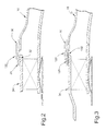
- the forward sleeve area is circled at 20 and cross-sectional views of example configurations thereof are provided in FIGURES 2 and 3.
- a forward sleeve retainer plate embodying the invention may be incorporated in either of said cross-sectional geometries and others.
- FIGURES 2 and 3 like reference numerals are used to identify structures corresponding to those discussed with reference to FIGURE 1 and reference numerals incremented by 100 indicate corresponding but structurally different parts.
- the transition piece forward sleeve assembly is the junction of the forward sleeve land 34 and the impingement sleeve 16.
- the impingement sleeve parts 24,26 are abutted to define the impingement sleeve 16.
- the forward sleeve 28 is disposed to encircle the leading end of the impingement sleeve 16 and the forward sleeve retainer plate 122 is welded to the forward sleeve as at 30 to hold the forward sleeve and hence the two halves of the impingement sleeve 16 tightly together.
- seal wear pads 32 are provided between the forward sleeve 28 and the forward sleeve land 34. Seal wear pads 32 are small pieces of metal that act as wear pads.
- FIGURE 3 depicts an alternate configuration of a forward sleeve assembly 20.
- a hula type wear seal 132 is disposed between the forward sleeve 128 and forward sleeve land 34.
- the forward sleeve 128 of the FIGURE 3 embodiment is recessed to accommodate the hula type wear seal 132.
- the forward sleeve retainer plate 122 configuration can be the same for each of the FIGURE 2 and FIGURE 3 assemblies. Further, the retainer plate of the invention can be included in other forward sleeve to forward sleeve land junctions without departing from the scope of this invention.
- impingement sleeve 16 is comprised of impingement sleeve halves 24,26 that are abutted as at 36 to define a split seam.
- the seal retainer plate is disposed to overlie the longitudinal junction (split seam) 36 of the impingement sleeve halves 24,26.
- the retainer plate 22 is welded to the forward sleeve 28,128 as schematically illustrated at 30, around its outer periphery on respective sides of the split seam.
- reference 40 identifies the outside corner where the fillet weld is typically started. This location is the area where the highest stresses would be seen on a conventional rectangular plate. Fillet welds in a structural application are generally not considered desirable because there is a built in crack between the two items being joined. One particularly bad area of the fillet weld configuration is the initiation point where the weld starts. This is because of the high rate of transition in the geometry of the parts and the resultant stress concentration.
- the improved sleeve retainer plate 122 of the invention lowers the stresses at the beginning of the fillet weld bead by including a stress relief feature in the form of a cutout 42,44 having a curved profile on at least one of the leading and trailing ends of the retainer plate.
- a stress field is formed in the retainer plate. Due to the stress reducing cutout(s) 42,44, however the stress field, (a part of which is schematically illustrated with dashed lines) is formed wherein the stress field is distributed so as not to concentrate and cause cracking in the plate.
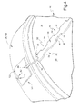
- a zipper strip 38 (FIGURE 4) is further disposed to overlie the junction of the impingement sleeve halves.
- the zipper strip is continuously welded along each side.
- the leading end of the zipper strip also includes a stress relief feature, illustrated at 46, in the form of a cutout having a curved profile.
- the stress relief feature is defined at the axial end(s) of the zipper strip where the end of the zipper strip overlies the junction of the impingement sleeve parts to redistribute the forces due to pressures on the impingement sleeve. This reduces stress concentration particularly at the initiation point of the fillet weld provided between the zipper strip and the impingement sleeve parts.
- the zipper strip illustrated in FIGURE 4 is elongated having spaced recesses 52 on each side thereof, along the length thereof. As illustrated, the recesses 52 have respectively curved leading 54 and trailing 56 ends, which also reduces stress concentration, and a straight portion 58.
- the stress relief features 42,44,46 are curved cutouts. More specifically, in the illustrated examples, the cutouts 42,44,46 are substantially continuously curved as at 48 from the outer periphery of the plate or zipper strip inwardly, but include a generally straight portion 50 parallel to the outer side edge. However, other stress relief feature configurations may be provided including a continuously curved cutout, semi-circular cutout, or the like.
- FIGURE 4 schematically depicts the retainer plate 122 as having corners that are substantial right angles. It is to be understood that rather than straight corners, the retainer plate can be formed with curved corners as depicted at 60 in the FIGURE 5 embodiment.
Landscapes
- Engineering & Computer Science (AREA)
- Mechanical Engineering (AREA)
- General Engineering & Computer Science (AREA)
- Chemical & Material Sciences (AREA)
- Combustion & Propulsion (AREA)
- Turbine Rotor Nozzle Sealing (AREA)
- Laser Beam Processing (AREA)
- Standing Axle, Rod, Or Tube Structures Coupled By Welding, Adhesion, Or Deposition (AREA)
Applications Claiming Priority (1)
| Application Number | Priority Date | Filing Date | Title |
|---|---|---|---|
| US11/402,857 US7681403B2 (en) | 2006-04-13 | 2006-04-13 | Forward sleeve retainer plate and method |
Publications (1)
| Publication Number | Publication Date |
|---|---|
| EP1847685A2 true EP1847685A2 (fr) | 2007-10-24 |
Family
ID=38016676
Family Applications (1)
| Application Number | Title | Priority Date | Filing Date |
|---|---|---|---|
| EP07105838A Withdrawn EP1847685A2 (fr) | 2006-04-13 | 2007-04-10 | Plaque avant de retenue de manchon et procédé |
Country Status (4)
| Country | Link |
|---|---|
| US (2) | US7681403B2 (fr) |
| EP (1) | EP1847685A2 (fr) |
| JP (1) | JP5306607B2 (fr) |
| KR (1) | KR101385890B1 (fr) |
Cited By (7)
| Publication number | Priority date | Publication date | Assignee | Title |
|---|---|---|---|---|
| WO2009103658A1 (fr) * | 2008-02-20 | 2009-08-27 | Alstom Technology Ltd | Turbine à gaz à chambre de combustion annulaire |
| WO2012161941A1 (fr) * | 2011-05-20 | 2012-11-29 | Siemens Energy, Inc. | Système de combustion de turbine s'accouplant à une plaque d'usure ajustable et procédé d'assemblage correspondant |
| EP2148139A3 (fr) * | 2008-07-21 | 2013-09-11 | United Technologies Corporation | Manchon d'écoulement avec refroidissement par projection utilisant un anneau de répartition |
| EP2216510A3 (fr) * | 2009-02-10 | 2014-03-05 | United Technologies Corporation | Ensemble de conduite de transition et systèmes de moteur à turbine à gaz impliquant de tels ensembles |
| US9163527B2 (en) | 2012-02-27 | 2015-10-20 | Hamilton Sundstrand Corporation | Burner pressure transducer thermal management design |
| EP3136000A1 (fr) * | 2015-08-24 | 2017-03-01 | General Electric Company | Système de patin d'usure pour systèmes de combustion à turbine et procédé de couplage d'un patin d'usure dans un système de combustion à turbine |
| WO2017058155A1 (fr) * | 2015-09-29 | 2017-04-06 | Siemens Aktiengesellschaft | Arrangement de refroidissement par contact pour conduites de transition de turbine à gaz |
Families Citing this family (14)
| Publication number | Priority date | Publication date | Assignee | Title |
|---|---|---|---|---|
| US7681403B2 (en) | 2006-04-13 | 2010-03-23 | General Electric Company | Forward sleeve retainer plate and method |
| US20100225902A1 (en) * | 2006-09-14 | 2010-09-09 | General Electric Company | Methods and apparatus for robotically inspecting gas turbine combustion components |
| US8544277B2 (en) * | 2007-09-28 | 2013-10-01 | General Electric Company | Turbulated aft-end liner assembly and cooling method |
| US9074005B2 (en) * | 2009-01-02 | 2015-07-07 | Washington State University | Compositions and methods for modulating plant disease resistance and immunity |
| US8549861B2 (en) * | 2009-01-07 | 2013-10-08 | General Electric Company | Method and apparatus to enhance transition duct cooling in a gas turbine engine |
| US8276391B2 (en) * | 2010-04-19 | 2012-10-02 | General Electric Company | Combustor liner cooling at transition duct interface and related method |
| US8448444B2 (en) | 2011-02-18 | 2013-05-28 | General Electric Company | Method and apparatus for mounting transition piece in combustor |
| EP2742291B1 (fr) * | 2011-08-11 | 2020-07-08 | General Electric Company | Système pour injecter du carburant dans un moteur à turbine à gaz |
| US9267687B2 (en) * | 2011-11-04 | 2016-02-23 | General Electric Company | Combustion system having a venturi for reducing wakes in an airflow |
| JP6092597B2 (ja) * | 2012-11-30 | 2017-03-08 | 三菱日立パワーシステムズ株式会社 | ガスタービン燃焼器 |
| WO2014179328A1 (fr) * | 2013-04-29 | 2014-11-06 | United Technologies Corporation | Joint pour fermer une fente entre des segments de carter d'une chambre de combustion de moteur à turbine à gaz industriel |
| US9739201B2 (en) | 2013-05-08 | 2017-08-22 | General Electric Company | Wake reducing structure for a turbine system and method of reducing wake |
| US9322553B2 (en) | 2013-05-08 | 2016-04-26 | General Electric Company | Wake manipulating structure for a turbine system |
| US9435221B2 (en) | 2013-08-09 | 2016-09-06 | General Electric Company | Turbomachine airfoil positioning |
Family Cites Families (17)
| Publication number | Priority date | Publication date | Assignee | Title |
|---|---|---|---|---|
| GB584820A (en) * | 1944-12-22 | 1947-01-23 | Lucas Ltd Joseph | Improvements relating to internal combustion prime movers |
| US2592060A (en) * | 1946-03-25 | 1952-04-08 | Rolls Royce | Mounting of combustion chambers in jet-propulsion and gas-turbine power-units |
| US4413470A (en) * | 1981-03-05 | 1983-11-08 | Electric Power Research Institute, Inc. | Catalytic combustion system for a stationary combustion turbine having a transition duct mounted catalytic element |
| US4567730A (en) | 1983-10-03 | 1986-02-04 | General Electric Company | Shielded combustor |
| US5361577A (en) * | 1991-07-15 | 1994-11-08 | General Electric Company | Spring loaded cross-fire tube |
| DE4223733C2 (de) * | 1992-07-18 | 1995-05-18 | Gutehoffnungshuette Man | Verbindung von Mischrohr und Flammrohr einer Gasturbine |
| US5400586A (en) * | 1992-07-28 | 1995-03-28 | General Electric Co. | Self-accommodating brush seal for gas turbine combustor |
| US6484505B1 (en) | 2000-02-25 | 2002-11-26 | General Electric Company | Combustor liner cooling thimbles and related method |
| US6412268B1 (en) | 2000-04-06 | 2002-07-02 | General Electric Company | Cooling air recycling for gas turbine transition duct end frame and related method |
| JP2004037035A (ja) * | 2002-07-05 | 2004-02-05 | Hitachi Ltd | ガスタービン燃焼器 |
| ITMI20031673A1 (it) * | 2003-08-28 | 2005-02-28 | Nuovo Pignone Spa | Sistema di fissaggio di un tubo di fiamma o "liner". |
| US7269957B2 (en) * | 2004-05-28 | 2007-09-18 | Martling Vincent C | Combustion liner having improved cooling and sealing |
| FR2871845B1 (fr) * | 2004-06-17 | 2009-06-26 | Snecma Moteurs Sa | Montage de chambre de combustion de turbine a gaz avec distributeur integre de turbine haute pression |
| US7647779B2 (en) * | 2005-04-27 | 2010-01-19 | United Technologies Corporation | Compliant metal support for ceramic combustor liner in a gas turbine engine |
| US7546743B2 (en) * | 2005-10-12 | 2009-06-16 | General Electric Company | Bolting configuration for joining ceramic combustor liner to metal mounting attachments |
| US7805946B2 (en) * | 2005-12-08 | 2010-10-05 | Siemens Energy, Inc. | Combustor flow sleeve attachment system |
| US7681403B2 (en) | 2006-04-13 | 2010-03-23 | General Electric Company | Forward sleeve retainer plate and method |
-
2006
- 2006-04-13 US US11/402,857 patent/US7681403B2/en not_active Expired - Fee Related
-
2007
- 2007-04-10 EP EP07105838A patent/EP1847685A2/fr not_active Withdrawn
- 2007-04-11 JP JP2007103589A patent/JP5306607B2/ja not_active Expired - Fee Related
- 2007-04-12 KR KR1020070036122A patent/KR101385890B1/ko not_active Expired - Fee Related
-
2010
- 2010-02-22 US US12/656,951 patent/US8327646B2/en not_active Expired - Fee Related
Cited By (14)
| Publication number | Priority date | Publication date | Assignee | Title |
|---|---|---|---|---|
| WO2009103658A1 (fr) * | 2008-02-20 | 2009-08-27 | Alstom Technology Ltd | Turbine à gaz à chambre de combustion annulaire |
| EP2148139A3 (fr) * | 2008-07-21 | 2013-09-11 | United Technologies Corporation | Manchon d'écoulement avec refroidissement par projection utilisant un anneau de répartition |
| EP2216510A3 (fr) * | 2009-02-10 | 2014-03-05 | United Technologies Corporation | Ensemble de conduite de transition et systèmes de moteur à turbine à gaz impliquant de tels ensembles |
| US8955331B2 (en) | 2011-05-20 | 2015-02-17 | Siemens Energy, Inc. | Turbine combustion system coupling with adjustable wear pad |
| KR20140015560A (ko) * | 2011-05-20 | 2014-02-06 | 지멘스 에너지, 인코포레이티드 | 조정 가능한 마모 패드를 구비한 터빈 연소 시스템 커플링 및 대응 조립 방법 |
| CN103717841A (zh) * | 2011-05-20 | 2014-04-09 | 西门子能量股份有限公司 | 联接有可调整的磨损垫的涡轮燃烧系统及相应的组装方式 |
| WO2012161941A1 (fr) * | 2011-05-20 | 2012-11-29 | Siemens Energy, Inc. | Système de combustion de turbine s'accouplant à une plaque d'usure ajustable et procédé d'assemblage correspondant |
| CN103717841B (zh) * | 2011-05-20 | 2016-01-20 | 西门子能量股份有限公司 | 联接有可调整的磨损垫的涡轮燃烧系统及相应的组装方式 |
| US9163527B2 (en) | 2012-02-27 | 2015-10-20 | Hamilton Sundstrand Corporation | Burner pressure transducer thermal management design |
| EP3136000A1 (fr) * | 2015-08-24 | 2017-03-01 | General Electric Company | Système de patin d'usure pour systèmes de combustion à turbine et procédé de couplage d'un patin d'usure dans un système de combustion à turbine |
| CN106482155A (zh) * | 2015-08-24 | 2017-03-08 | 通用电气公司 | 涡轮燃烧系统的防磨衬垫系统和联接防磨衬垫的方法 |
| US10634349B2 (en) | 2015-08-24 | 2020-04-28 | General Electric Company | Wear pad system for turbine combustion systems and method for coupling wear pad into turbine combustion system |
| CN106482155B (zh) * | 2015-08-24 | 2020-12-15 | 通用电气公司 | 涡轮燃烧系统的防磨衬垫系统和联接防磨衬垫的方法 |
| WO2017058155A1 (fr) * | 2015-09-29 | 2017-04-06 | Siemens Aktiengesellschaft | Arrangement de refroidissement par contact pour conduites de transition de turbine à gaz |
Also Published As
| Publication number | Publication date |
|---|---|
| US20070251240A1 (en) | 2007-11-01 |
| KR20070101806A (ko) | 2007-10-17 |
| JP2007285692A (ja) | 2007-11-01 |
| US20100154436A1 (en) | 2010-06-24 |
| US8327646B2 (en) | 2012-12-11 |
| JP5306607B2 (ja) | 2013-10-02 |
| US7681403B2 (en) | 2010-03-23 |
| KR101385890B1 (ko) | 2014-04-15 |
Similar Documents
| Publication | Publication Date | Title |
|---|---|---|
| US8327646B2 (en) | Forward sleeve retainer plate and method | |
| US3936206A (en) | Tubular pole slip joint construction | |
| EP2245358B1 (fr) | Serre-joint à sangle à boulon unique doté d'une nervure centrale à joints et joint à recouvrement de tuyau utilisant le serre-joint | |
| US7845857B2 (en) | Thrust bearing assembly | |
| US7938626B2 (en) | Shim for a turbojet blade | |
| KR101872043B1 (ko) | 동체 섹션들을 결합하기 위한 이음부 및 이와 관련된 방법 | |
| US20100180417A1 (en) | Replacement of part of engine case with dissimilar material | |
| EP3246610B1 (fr) | Tuyau caréné | |
| JPH0765604B2 (ja) | ひだ付き蛇腹を固定するエンドレス嵌合リング | |
| US5544849A (en) | Swaged wear sleeve and method | |
| US7708319B2 (en) | Piping joint structure | |
| EP1010928A2 (fr) | Collier de serrage | |
| US9068459B2 (en) | Turbine diaphragm airfoil, diaphragm assembly, and method of repair | |
| EP1092840A1 (fr) | Distributeur assemblé pour turbine à vapeur | |
| US4797065A (en) | Turbine blade retainer | |
| US12104719B2 (en) | Element joint and manufacturing method therefor | |
| JP2003287128A (ja) | 2ピース型組合せオイルリング | |
| US7062887B1 (en) | Intersecting structural member and a method for joining same | |
| CN100447384C (zh) | 车辆排气管的连接结构 | |
| JP4578386B2 (ja) | 排気管とフランジの溶接方法 | |
| US5116084A (en) | Steel eyejoint | |
| US12172245B2 (en) | Extruded weld joint backing insert | |
| JP7560032B2 (ja) | セグメントの連結構造 | |
| US20040150208A1 (en) | Vehicle structure having cross members overlapped by apertured rails | |
| JP3208511B2 (ja) | エンジンバルブ及びバルブガイド |
Legal Events
| Date | Code | Title | Description |
|---|---|---|---|
| PUAI | Public reference made under article 153(3) epc to a published international application that has entered the european phase |
Free format text: ORIGINAL CODE: 0009012 |
|
| AK | Designated contracting states |
Kind code of ref document: A2 Designated state(s): AT BE BG CH CY CZ DE DK EE ES FI FR GB GR HU IE IS IT LI LT LU LV MC MT NL PL PT RO SE SI SK TR |
|
| AX | Request for extension of the european patent |
Extension state: AL BA HR MK YU |
|
| STAA | Information on the status of an ep patent application or granted ep patent |
Free format text: STATUS: THE APPLICATION IS DEEMED TO BE WITHDRAWN |
|
| 18D | Application deemed to be withdrawn |
Effective date: 20141101 |