EP1847773B1 - Refroidisseur de cendres intégré pour lit fluidisé - Google Patents
Refroidisseur de cendres intégré pour lit fluidisé Download PDFInfo
- Publication number
- EP1847773B1 EP1847773B1 EP07251631.3A EP07251631A EP1847773B1 EP 1847773 B1 EP1847773 B1 EP 1847773B1 EP 07251631 A EP07251631 A EP 07251631A EP 1847773 B1 EP1847773 B1 EP 1847773B1
- Authority
- EP
- European Patent Office
- Prior art keywords
- fluidized bed
- section
- ash
- ash cooler
- cooler
- Prior art date
- Legal status (The legal status is an assumption and is not a legal conclusion. Google has not performed a legal analysis and makes no representation as to the accuracy of the status listed.)
- Not-in-force
Links
Images




Classifications
-
- F—MECHANICAL ENGINEERING; LIGHTING; HEATING; WEAPONS; BLASTING
- F23—COMBUSTION APPARATUS; COMBUSTION PROCESSES
- F23C—METHODS OR APPARATUS FOR COMBUSTION USING FLUID FUEL OR SOLID FUEL SUSPENDED IN A CARRIER GAS OR AIR
- F23C10/00—Fluidised bed combustion apparatus
- F23C10/18—Details; Accessories
-
- F—MECHANICAL ENGINEERING; LIGHTING; HEATING; WEAPONS; BLASTING
- F23—COMBUSTION APPARATUS; COMBUSTION PROCESSES
- F23J—REMOVAL OR TREATMENT OF COMBUSTION PRODUCTS OR COMBUSTION RESIDUES; FLUES
- F23J1/00—Removing ash, clinker, or slag from combustion chambers
-
- F—MECHANICAL ENGINEERING; LIGHTING; HEATING; WEAPONS; BLASTING
- F23—COMBUSTION APPARATUS; COMBUSTION PROCESSES
- F23J—REMOVAL OR TREATMENT OF COMBUSTION PRODUCTS OR COMBUSTION RESIDUES; FLUES
- F23J2900/00—Special arrangements for conducting or purifying combustion fumes; Treatment of fumes or ashes
- F23J2900/01002—Cooling of ashes from the combustion chamber by indirect heat exchangers
Definitions
- the present invention relates, in general, to fluidized bed ash coolers and, more particularly, to an integrated fluidized bed ash cooler which facilitates the removal of ash while minimizing the possibility of ash plugging during operation.
- Fluidized bed bottom ash coolers are widely used in fluidized bed combustion technology.
- the bottom ash removed from fluidized bed combustors contains a significant amount of heat. Removal of the heat in the bottom ash reduces the temperature of the ash, thereby facilitating handling and disposal of same. Recovery of the heat in the bottom ash is also desirable in order to enhance the overall thermal efficiency of the fluidized bed combustion plant. Fluidization of the ash in the ash cooler sharply enhances heat transfer between the ash and the cooling medium which allows for the size of the ash cooler to be reduced.
- Typical existing prior art fluidized bed bottom ash coolers for a circulating fluidized bed (CFB) boiler are shown in Figs. 1, 2 , 3 and 4 .
- Figs. 1 and 2 illustrate a typical fluidized bed bottom ash cooler 10 which is provided within a refractory-lined box or enclosure and supported off of boiler structural steel.
- the ash cooler 10 is provided within a fluid-cooled (typically water and/or steam-cooled) enclosure formed of membrane tube wall panels.
- the fluidized bed ash cooler 10 is still a structure separate from the CFB furnace 20, and separately supported off of the boiler structural steel.
- ash for cooling is transferred from the CFB furnace 20 to the fluidized bed ash cooler 10 via an air-assisted conduit 30 connected between the CFB furnace 20 and a lower part of the ash cooler 10.
- the ash is fluidized within the ash cooler 10, typically with fluidization air supplied through the bottom of the enclosure surrounding the ash cooler 10, whether refractory-lined or water-cooled. Cooling of the ash within the ash cooler 10 takes place through heat exchange between the (relatively) cold air provided for fluidization and the hot ash.
- the heated air is then conveyed back to the CFB furnace 20 via a conduit 40 connected to an upper part of the ash cooler 10.
- Cooled ash is discharged via a drain (not shown) at the bottom of the ash cooler 10.
- the ash cooler 10 may include heat absorbing surface, typically water-cooled tube banks 50, placed within the fluidized ash bed established within the ash cooler 10. In such a case, a bulk of the heat from the hot bottom ash transferred from the CFB furnace 20 into the ash cooler 10 would be absorbed by the cooling water circulated through the water-cooled tube banks 50 with the air provided into the ash cooler 10 primarily playing the role of the fluidizing medium.
- the existing ash coolers provide necessary ash cooling and enhance boiler efficiency by returning the heat absorbed from the ash back to the boiler system
- the existing ash coolers have several shortcomings including: a complicated support structure, the need for high-temperature expansion joints to accommodate differences in thermal expansion between the ash cooler and the furnace, and complexity of solids transfer from the furnace to the ash cooler.
- GB 2148734A relates to a divided fluidised bed.
- WO 97/27903 A1 relates to an apparatus and method for treating solids.
- Example embodiments of the present disclosure can overcome shortcomings such as those described above, and can provide other advantages, while simultaneously allowing for reductions in the size, weight and cost of the ash cooler.
- thermocouple means for measuring a bed temperature T1 in the vicinity of the fluidizing means, and also thermocouple means for measuring temperature T2 at a higher elevation, which is above thermocouple means for measuring the bed temperature T1, within the fluidized bed, and means for removing oversized bed material from the first section when a temperature difference, T2 -T1, between the temperature of stagnant bed material, T1, and the temperature of fluidized bed material above, T2, the temperature difference being indicative of an accumulation of bed material in a lower part of the first section, is detected by the thermocouple
- the fluidized bed ash cooler comprises at least two fluidized bed sections positioned in series along a solids flow path, each section containing fluidizing means.
- the first section along the solids path is separated from a following section with a threshold, the first section containing means for measuring the solids temperature in the vicinity of the fluidizing means and at a higher elevation within the fluidized bed.
- Means are provided for removing oversized bed material from the first section.
- Yet another aspect of the disclosure is to provide an integrated fluidized bed ash cooler which is simple in design, rugged in construction and economical to manufacture.
- FIG. 1 a first embodiment of an integrated fluidized bed ash cooler
- the integrated fluidized bed ash cooler 100 is provided as an integral part of a circulating fluidized bed (CFB) furnace 110 having furnace walls 120.
- the ash cooler 100 can be formed of membrane tube wall panels 130 one of which is a part of one of the furnace walls 120. While it is most likely that such membrane wall construction would be employed for both the fluidized bed furnace 110 and the fluidized bed ash cooler 100, it is possible that an uncooled enclosure wall construction could be employed for both the ash cooler 100 and the fluidized bed furnace 110. The principles of the present invention are applicable to such constructions as well.
- all of the furnace walls 120 and membrane tube wall panels 130 are included in the furnace 110 circulation circuits.
- There are at least two openings in the furnace wall 120 which is a common wall shared with the ash cooler 100.
- a lower inlet opening 150 provides means for conveying or transferring hot ash from the CFB furnace 110 into the ash cooler 100.
- An upper outlet opening 160 provides means for conveying heated air (or other fluidizing and cooling medium) from the ash cooler 100 back into the CFB furnace 110.
- the fluidizing medium is supplied to the ash cooler 100 from a windbox 170 through fluidizing means such as bubble caps 180.
- the bubble caps 180 provide the means for fluidizing the solids and the "position" of the fluidizing means is essentially established by the location of the exit holes in the bubble caps which deliver the fluidizing medium into the bed of solids.
- a cooling medium is circulated through the enclosure walls 120 of the fluidized bed furnace 110 and the fluidized bed ash cooler 100.
- the flow of cooling medium through the common wall is predominantly upflow and, in one embodiment, the flow of cooling medium through the remaining enclosure walls 130 of the fluidized bed cooler 100 is predominantly downflow.
- the cooling medium is at least one of water and a mixture of water and steam.
- the common wall is provided with two openings, the upper opening 160 for discharging hot fluidizing medium from the fluidized bed ash cooler 100 into the fluidized bed furnace 110, and a lower opening 150 for conveying bottom ash solids from the fluidized bed furnace 110 into the fluidized bed ash cooler 100.
- baffles 190 immersed within a fluidized bed 200 of ash cause the fluidized ash particles to proceed along a tortuous path from the lower inlet opening 150 to a discharge opening 210. This helps to ensure adequate residence time for cooling of all ash particles provided into the ash cooler 100.
- the bottom ash discharge rate from opening 210 is controlled by a feeder means (illustrated as 215 in Fig. 10 ), such as a screw conveyor, which generally runs continuously as needed for removal of bottom ash from the furnace 110.
- the windbox 170 (not shown in Fig.
- the baffles 190 can be partitioned to provide means for separately controlling the flow of the fluidizing medium into different sections of the fluidized bed 200 of ash particles as those sections may be defined by the baffles 190.
- different fluidizing mediums can be supplied to different sections of the fluidized bed 200; e.g., flue gas may be provided to a particular section or sections 220 located adjacent to the lower inlet opening 150, while air may be advantageously provided to other sections of the fluidized bed 200.
- flue gas may be provided to a particular section or sections 220 located adjacent to the lower inlet opening 150, while air may be advantageously provided to other sections of the fluidized bed 200.
- This flexibility allows prevention of combustion of unburned carbon in the bottom ash that might otherwise occur, especially in the case of firing low reactive fuels such as anthracite.
- Other means for preventing high temperatures in the first section can include spraying water into the fluidized bed in this section. Spraying water into the fluidized bed, in general, may be utilized for lowering the bed temperature down
- the height of the fluidized bed 200 at any given moment is such as to compensate a pressure differential between the openings 150 and 160 which, in turn, is determined by the pressure profile within the CFB furnace 110.
- the membrane tube wall panels 130 may be partially or completely coated with refractory 230 to prevent erosion.
- Refractory 240 protects the CFB furnace walls 120 in the lower portion of the CFB furnace 110.
- tube banks 250 supplied with a cooling medium could be provided and immersed within the fluidized bed 200 to provide for additional heat absorption from the hot ash.
- the cooling medium conveyed through some or all of the tube banks 250 could be supplied from different sources, such as boiler feed water, water or steam from an external source (with respect to the CFB furnace or boiler circulation circuits).
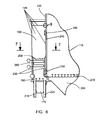
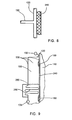
- At least some of the tube banks 250 can be incorporated into the CFB boiler circulation circuits, as illustrated in Figs. 8 and 9 .
- some of the tubes forming the membrane tube wall panels 130 of the ash cooler 100 may be combined at a "tee" section with the tubes forming the CFB furnace walls 120.
- some of the tubes forming the ash cooler 100 membrane tube wall panels 130 may be part of a separate fluid circuit where the cooling medium may be provided via an inlet header 132, flowing through the tubes in the panels 130 to an outlet header 134.
- the flow in this instance would be predominantly downwardly, the inlet header 132 being located at a higher elevation than the outlet header 134.
- a fuel fired in the CFB may contain rocks or form agglomerates during combustion. These rocks or agglomerates can be reliably fluidized in a CFB furnace, because of its comparatively high gas velocity.
- the velocity of the fluidizing medium in an ash cooler which would be typically several times less than that seen in a CFB furnace, may be not sufficient for reliable fluidization of those rocks or agglomerates. In such a case, accumulation of coarse fractions in the ash cooler will occur, resulting in its pluggage and eventual shutdown.
- a first section 220 adjacent to the lower inlet opening 150 is equipped with its own solids discharge opening 225.
- Coarse fractions such as rocks or agglomerates will tend to sink to the bottom of this first section 220 from where they will be timely discharged without having to move along and through the ash cooler 100 to the discharge opening 210 and eventually removed by feeder means 215. Since the throughput of the coarse particles is relatively small compared to the total flow rate of the bottom ash, the coarse ash particles will normally be sufficiently cooled during their movement downward along the bubble caps 180 of the first section 220 for conveyance by the feeder means 215.
- water spray nozzle means 310 which can be used to spray water into these coarse ash particles before they are discharged through discharge opening 225 and conveyed away via feeder means 300.
- Water spray nozzle means 320 may also be provided to cool the bottom ash in the first section 220.
- water spray nozzle means 330 may also be provided for supplemental cooling of the bottom ash before it is discharged through discharge opening 210 and conveyed away via feeder means 215.
- an important feature of the present embodiment involves creating what is termed a "threshold" T between the first section 220 and the following sections 220 within the fluidized bed ash cooler 100 for preventing coarse bottom ash solids from passing from the first section 220 into those following, downstream sections.
- a threshold T between the first section 220 and the following sections 220 within the fluidized bed ash cooler 100 for preventing coarse bottom ash solids from passing from the first section 220 into those following, downstream sections.
- fluidizing means such as an array of bubble caps 180 forming a distribution grid
- the threshold is formed by a wall (such as partition 190) which has an aperture 280 and an edge 290 located above the fluidizing means of the first section 220.
- the function of the threshold can be provided by positioning the fluidizing means 180 in the first section 220 at a lower elevation than an elevation of fluidizing means 180 in the following section 220.
- the first section 220 contains means, such as thermocouples, for measuring a bed temperature both in the vicinity of the fluidizing means (as at T 1 ) and at a higher elevation (as at T 2 ) within the fluidized bed 200.
- means such as thermocouples, for measuring a bed temperature both in the vicinity of the fluidizing means (as at T 1 ) and at a higher elevation (as at T 2 ) within the fluidized bed 200.
- thermocouple means for measuring the bed temperature and signals the accumulation of the coarse material in the lower part of the first section 220.
- This signal triggers the discharge of the bed material from the first section 220 by activating feeder means 300, such as a screw conveyor. The discharge continues until the elimination of the temperature difference, which is indicative of fluidization of the entire bed of material in the first section 220.
- Another way to enhance separation of the coarse particles in the first section 220, as well as improving the overall reliability of the ash cooler 100, is by maintaining the fluidizing velocity in this first section 220 at a lower value than the fluidization velocity maintained in following (downstream) sections 220 of the ash cooler 100.
- the higher the fluidization velocity the higher the likelihood that particles of a given size will be fluidized, as opposed to sinking. Therefore, the ash particles which did not sink in the first section 220 will be reliably fluidized in the other downstream sections 220 of the ash cooler 100.
- Fluidizing medium is supplied to every section 220 of the ash cooler 100 at a controlled rate to maintain a desired fluidization velocity in each section.
- the mass flow rate to a given ash cooler section 220 is automatically adjusted based upon the bed temperature in that section in order to maintain a pre-set fluidization velocity. For example, an increase in the bed temperature in a section will result in a reduction of the fluidizing medium mass flow rate to that section in order to compensate for the increased specific volume of the fluidizing medium.
- the integrated fluidized bed ash cooler has several advantages over the ash cooler designs of the prior art.
- the ash cooler 100 enclosure walls are made of membrane tube wall panels which are incorporated into the CFB boiler circulation circuits, as are all the panels forming the CFB furnace walls, the wall temperature and thermal expansion of the ash cooler 100 always follows that of the CFB furnace. This eliminates a need for high temperature expansion joints on the conduits between the ash cooler 100 and the CFB furnace, simplifying the design, and reducing maintenance and improving reliability of the ash cooler 100.
- the overall size and weight of both the ash cooler 100 and its support structure is greatly simplified, resulting in further cost reductions.
- Using a simple opening instead of the prior art air-assisted conduit for transferring ash from the CFB furnace into the ash cooler 100 also improves reliability and reduces maintenance of the ash cooler 100. Cooling and removing bottom ash from fuels containing rocks or forming agglomerates can be reliably performed by discharging coarser particles from the first section of the ash cooler 100. Separation of the coarser particles can be enhanced by maintaining a reduced velocity of the fluidizing medium in the first section of the ash cooler 100.
- an integrated fluidized bed ash cooler for a fluidized bed boiler employs at least two fluidized bed sections positioned in series along a solids flow path.
- Each section contains fluidizing means, the first section along the solids path being separated from a following section with a threshold.
- the first section contains means for measuring a bed temperature in the vicinity of the fluidizing means and at a higher elevation within the fluidized bed.
- Means are provided for removing oversized bed material from the first section to facilitate the removal of ash while minimizing the possibility of ash plugging during operation.
Landscapes
- Engineering & Computer Science (AREA)
- Mechanical Engineering (AREA)
- General Engineering & Computer Science (AREA)
- Chemical & Material Sciences (AREA)
- Combustion & Propulsion (AREA)
- Fluidized-Bed Combustion And Resonant Combustion (AREA)
- Crucibles And Fluidized-Bed Furnaces (AREA)
Claims (16)
- Refroidisseur (100) de cendres pour lit fluidisé, servant à refroidir des solides de cendre de fond provenant d'un four (110) à lit fluidisé, comportant :au moins deux sections (220) de lit fluidisé positionnées en série le long d'un parcours d'écoulement de solides, chaque section contenant des moyens (180) de fluidisation ;la première section le long du parcours d'écoulement de solides comportant une ouverture (150) servant à recevoir de la cendre de four à lit fluidisé provenant de l'extérieur du refroidisseur (100) de cendres,la première section étant séparée d'une section suivante du refroidisseur (100) de cendres par un seuil (T) ;caractérisé en ce quela première section contient des moyens de thermocouple servant à mesurer une température de lit T1 au voisinage des moyens (180) de fluidisation,et également des moyens de thermocouple servant à mesurer une température T2 à une hauteur supérieure,qui se situe au-dessus des moyens de thermocouple servant à mesurer la température de lit T1, à l'intérieur du lit fluidisé (200),et des moyens servant à évacuer (225) des matières de lit surdimensionnées de la première section lorsqu'une différence de température, T2-T1, entre la température des matières de lit stagnantes, T1, et la température des matières de lit fluidisées situées au-dessus, T2, la différence de température étant indicative d'une accumulation de matières de lit dans une partie inférieure de la première section, est détectée par les moyens de thermocouple.
- Refroidisseur de cendres pour lit fluidisé selon la revendication 1, le seuil (T) étant formé par une paroi (190) qui présente un bord supérieur (290) situé au-dessus des moyens (180) de fluidisation de la première section.
- Refroidisseur de cendres pour lit fluidisé selon la revendication 1, le seuil (T) étant formé en positionnant les moyens (180) de fluidisation dans la première section à une hauteur inférieure à une hauteur de moyens (180) de fluidisation dans la section suivante.
- Refroidisseur de cendres pour lit fluidisé selon l'une quelconque des revendications précédentes, la première section ne contenant aucune surface absorbant la chaleur immergée dans le lit fluidisé.
- Refroidisseur de cendres pour lit fluidisé selon l'une quelconque des revendications précédentes, comportant des moyens servant à abaisser une température de lit d'une section lorsque ladite température dépasse une valeur prédéfinie.
- Refroidisseur de cendres pour lit fluidisé selon la revendication 5, les moyens servant à abaisser la température de lit comportant des moyens (310, 320, 330) servant à pulvériser de l'eau dans le lit fluidisé.
- Refroidisseur de cendres pour lit fluidisé selon l'une quelconque des revendications précédentes, comportant des moyens servant à maintenir une vitesse constante de milieu fluidisant dans chaque section.
- Refroidisseur de cendres pour lit fluidisé selon la revendication 7, les moyens de maintien de la vitesse constante comportant des moyens servant à réguler automatiquement le débit massique du milieu fluidisant vers une section donnée d'après la température de lit dans la section en question.
- Refroidisseur de cendres pour lit fluidisé selon l'une quelconque des revendications précédentes, comportant des moyens (310) servant à refroidir des matières surdimensionnées de cendre de fond qui sont évacuées de la première section en pulvérisant de l'eau dans les matières surdimensionnées de cendre de fond.
- Refroidisseur de cendres pour lit fluidisé selon l'une quelconque des revendications précédentes, comportant des moyens servant à maintenir une plus basse vitesse de fluidisation dans la première section par rapport à une vitesse de fluidisation dans les sections suivantes.
- Refroidisseur de cendres pour lit fluidisé selon l'une quelconque des revendications précédentes, comportant une boîte à vent cloisonnée (170) servant à réguler séparément le débit de milieu fluidisant entrant dans différentes sections du lit fluidisé pour maintenir une plus basse vitesse de fluidisation dans la première section par rapport à une vitesse de fluidisation dans les sections suivantes.
- En combinaison, un four (110) à lit fluidisé doté de parois (120) d'enceinte et d'un refroidisseur (100) de cendres pour lit fluidisé selon l'une quelconque des revendications précédentes servant à refroidir des solides de cendre de fond provenant du four à lit fluidisé, le four à lit fluidisé et le refroidisseur de cendres partageant ensemble une paroi commune (120).
- Combinaison selon la revendication 12, des parois d'enceinte du refroidisseur pour lit fluidisé et du four à lit fluidisé étant constituées de panneaux (130) parois à tubes en membrane.
- Combinaison selon la revendication 12 ou revendication 13, un milieu de refroidissement étant mis en circulation à travers les parois d'enceinte du four à lit fluidisé et du refroidisseur de cendres pour lit fluidisé, et l'écoulement de milieu de refroidissement à travers la paroi commune étant majoritairement ascendant et l'écoulement de milieu de refroidissement à travers les parois d'enceinte restantes du refroidisseur pour lit fluidisé étant majoritairement descendant.
- Combinaison selon la revendication 14, le milieu de refroidissement étant au moins un milieu parmi de l'eau et un mélange d'eau water et de vapeur.
- Combinaison selon l'une quelconque des revendications 12 à 15, la paroi commune étant munie de deux ouvertures, une ouverture supérieure (160) servant à évacuer du milieu fluidisant chaud du refroidisseur de cendres pour lit fluidisé jusque dans le four à lit fluidisé, et une ouverture inférieure (150) servant à acheminer des solides de cendres de fond du four à lit fluidisé jusque dans le refroidisseur de cendres pour lit fluidisé.
Priority Applications (1)
| Application Number | Priority Date | Filing Date | Title |
|---|---|---|---|
| PL07251631T PL1847773T3 (pl) | 2006-04-19 | 2007-04-18 | Zintegrowany schładzacz popiołu ze złoża fluidalnego |
Applications Claiming Priority (1)
| Application Number | Priority Date | Filing Date | Title |
|---|---|---|---|
| US11/406,765 US7464669B2 (en) | 2006-04-19 | 2006-04-19 | Integrated fluidized bed ash cooler |
Publications (3)
| Publication Number | Publication Date |
|---|---|
| EP1847773A2 EP1847773A2 (fr) | 2007-10-24 |
| EP1847773A3 EP1847773A3 (fr) | 2014-01-08 |
| EP1847773B1 true EP1847773B1 (fr) | 2015-12-30 |
Family
ID=38220691
Family Applications (1)
| Application Number | Title | Priority Date | Filing Date |
|---|---|---|---|
| EP07251631.3A Not-in-force EP1847773B1 (fr) | 2006-04-19 | 2007-04-18 | Refroidisseur de cendres intégré pour lit fluidisé |
Country Status (8)
| Country | Link |
|---|---|
| US (1) | US7464669B2 (fr) |
| EP (1) | EP1847773B1 (fr) |
| CA (1) | CA2585400C (fr) |
| ES (1) | ES2564792T3 (fr) |
| HU (1) | HUE028669T2 (fr) |
| PL (1) | PL1847773T3 (fr) |
| RU (1) | RU2436013C2 (fr) |
| UA (1) | UA94697C2 (fr) |
Families Citing this family (28)
| Publication number | Priority date | Publication date | Assignee | Title |
|---|---|---|---|---|
| FI20031113A7 (fi) * | 2003-07-29 | 2005-01-30 | Outokumpu Oy | Menetelmä ja laitteisto leijupetiuunin arinalta poistettavan materiaalin jäähdyttämiseksi |
| US8968431B2 (en) * | 2008-06-05 | 2015-03-03 | Synthesis Energy Systems, Inc. | Method and apparatus for cooling solid particles under high temperature and pressure |
| US8434430B2 (en) * | 2009-09-30 | 2013-05-07 | Babcock & Wilcox Power Generation Group, Inc. | In-bed solids control valve |
| FI122189B (fi) * | 2009-12-21 | 2011-09-30 | Foster Wheeler Energia Oy | Menetelmä ja järjestely lämmön talteenottamiseksi palamisprosessin pohjatuhkasta |
| US9074767B2 (en) * | 2010-02-11 | 2015-07-07 | Alstom Technology Ltd | Rotary bottom ash regeneration system |
| PH12013500244A1 (en) | 2010-08-09 | 2017-02-01 | Southern Co | Ash and solids cooling in high temperature and high pressure environment |
| CN101943403B (zh) * | 2010-09-30 | 2011-11-23 | 重庆大学 | 双分选式流化床冷渣器 |
| CN102221201A (zh) * | 2011-04-01 | 2011-10-19 | 张全胜 | 循环流化床锅炉的等床压冷渣流化床及运行方法 |
| DE102012002711A1 (de) * | 2012-02-14 | 2013-08-14 | Thyssenkrupp Uhde Gmbh | Bodenproduktkühlung bei einer Wirbelschichtvergasung |
| US20130312946A1 (en) * | 2012-05-24 | 2013-11-28 | Kellogg Brown & Root Llc | Methods and Systems for Cooling Hot Particulates |
| CN103574596B (zh) * | 2012-07-20 | 2016-03-02 | 青岛达能环保设备股份有限公司 | 耐压行星管圈式滚筒冷渣机 |
| WO2014152073A2 (fr) * | 2013-03-15 | 2014-09-25 | Synthesis Energy Systems, Inc. | Procédé et appareil pour le refroidissement de cendre |
| CN103292320A (zh) * | 2013-05-31 | 2013-09-11 | 神华集团有限责任公司 | 循环流化床锅炉和使用循环流化床锅炉的流化方法 |
| CN103819208A (zh) * | 2013-12-27 | 2014-05-28 | 中国神华能源股份有限公司 | 一种制备SiC晶须增韧Al2O3耐磨耐火材料的方法及由该方法制备的材料 |
| CN104990086B (zh) * | 2015-07-01 | 2018-05-22 | 集美大学 | 一种流化床垃圾焚烧炉 |
| DK3130849T3 (en) * | 2015-08-11 | 2018-09-24 | Doosan Lentjes Gmbh | Circulating fluid bed furnace |
| CN105180163B (zh) * | 2015-09-18 | 2017-11-17 | 青岛达能环保设备股份有限公司 | 循环流化床锅炉分级冷却排渣系统 |
| US9989244B2 (en) * | 2016-03-01 | 2018-06-05 | The Babcock & Wilcox Company | Furnace cooling by steam and air injection |
| CN107023843A (zh) * | 2017-05-03 | 2017-08-08 | 四川钜鼎节能环保科技有限公司 | 一种立式冷渣机 |
| CN106949463A (zh) * | 2017-05-03 | 2017-07-14 | 四川钜鼎节能环保科技有限公司 | 一种膜式壁高效冷渣机 |
| FI127753B (en) | 2017-06-09 | 2019-01-31 | Bioshare Ab | Recycling of chemicals from fuel streams |
| CN109827172B (zh) * | 2019-03-29 | 2023-08-18 | 重庆科技学院 | 循环流化床锅炉高温底渣冷却及余热回收利用装置 |
| CN110220189B (zh) * | 2019-06-17 | 2020-10-02 | 联盛纸业(龙海)有限公司 | 一种提高锅炉排渣效率的方法 |
| CN110925750B (zh) * | 2019-12-31 | 2021-05-11 | 济南黄台煤气炉有限公司 | 一种锅炉流化床多级冷渣系统 |
| US11752480B2 (en) | 2021-02-04 | 2023-09-12 | Babcock & Wilcox Company | Apparatus for enclosing a chemical looping process |
| WO2022235630A1 (fr) | 2021-05-03 | 2022-11-10 | Gas Technology Institute | Gestion de température oxy-pfbc par injection étagée de gaz et gestion de vitesse de gaz |
| CN114479944B (zh) * | 2021-12-21 | 2023-10-27 | 中国科学院工程热物理研究所 | 冷渣装置及流化床气化炉 |
| WO2025052025A1 (fr) * | 2023-09-06 | 2025-03-13 | Metso Metals Oy | Refroidisseur à lit fluidisé et procédé de refroidissement d'écoulement de matériau dans un refroidisseur à lit fluidisé |
Family Cites Families (22)
| Publication number | Priority date | Publication date | Assignee | Title |
|---|---|---|---|---|
| GB1509424A (en) * | 1975-04-30 | 1978-05-04 | Airflo Ltd | Heat exchangers for heating air |
| US4257338A (en) * | 1978-09-21 | 1981-03-24 | Chasek Norman E | Process for improved solid fuel combustion |
| DE3102819A1 (de) * | 1980-01-29 | 1982-02-18 | Babcock-Hitachi K.K., Tokyo | Verfahren fuer die rueckgwinnung von waerme bei der kohlevergasung und vorrichtung dafuer |
| US4453495A (en) * | 1983-03-23 | 1984-06-12 | Electrodyne Research Corporation | Integrated control for a steam generator circulating fluidized bed firing system |
| GB8327074D0 (en) * | 1983-10-10 | 1983-11-09 | English Electric Co Ltd | Fluidised-bed heat and power plant |
| ATE58218T1 (de) * | 1985-02-28 | 1990-11-15 | Sermet Oy | Brenner speziell fuer biomasse. |
| WO1987005089A1 (fr) * | 1986-02-14 | 1987-08-27 | Ebara Corporation | Procede de combustion de matieres combustibles dans un lit fluidise |
| US5013336A (en) * | 1989-11-03 | 1991-05-07 | Aluminum Company Of America | Method and apparatus for emission control |
| US5095854A (en) * | 1991-03-14 | 1992-03-17 | Foster Wheeler Development Corporation | Fluidized bed reactor and method for operating same utilizing an improved particle removal system |
| US5140950A (en) * | 1991-05-15 | 1992-08-25 | Foster Wheeler Energy Corporation | Fluidized bed combustion system and method having an integral recycle heat exchanger with recycle rate control and backflow sealing |
| US5218932A (en) * | 1992-03-02 | 1993-06-15 | Foster Wheeler Energy Corporation | Fluidized bed reactor utilizing a baffle system and method of operating same |
| US5372791A (en) * | 1992-04-20 | 1994-12-13 | Foster Wheeler Energy Corporation | Fluidized bed system and a fluidization and cooling nozzle for use therein |
| US5332553A (en) * | 1993-04-05 | 1994-07-26 | A. Ahlstrom Corporation | Method for circulating solid material in a fluidized bed reactor |
| US5540894A (en) * | 1993-05-26 | 1996-07-30 | A. Ahlstrom Corporation | Method and apparatus for processing bed material in fluidized bed reactors |
| US5390612A (en) * | 1993-03-01 | 1995-02-21 | Foster Wheeler Energy Corporation | Fluidized bed reactor having a furnace strip-air system and method for reducing heat content and increasing combustion efficiency of drained furnace solids |
| US5546875A (en) * | 1993-08-27 | 1996-08-20 | Energy And Environmental Research Center Foundation | Controlled spontaneous reactor system |
| US5526938A (en) * | 1994-10-07 | 1996-06-18 | The Babcock & Wilcox Company | Vertical arrangement fluidized/non-fluidized bed classifier cooler |
| US5522160A (en) * | 1995-01-05 | 1996-06-04 | Foster Wheeler Energia Oy | Fluidized bed assembly with flow equalization |
| WO1997027903A1 (fr) * | 1996-01-30 | 1997-08-07 | Vial Jean Luc | Appareil et procede de traitement de matieres solides |
| CN1262791C (zh) * | 1998-06-16 | 2006-07-05 | 三菱重工业株式会社 | 流化床焚烧炉及其运行方法 |
| RU2206823C1 (ru) * | 2002-04-08 | 2003-06-20 | Иванов Виктор Евгеньевич | Топочное устройство |
| RU2236641C1 (ru) * | 2003-05-20 | 2004-09-20 | Владимирский государственный университет | Способ сжигания твердого топлива |
-
2006
- 2006-04-19 US US11/406,765 patent/US7464669B2/en active Active
-
2007
- 2007-04-18 PL PL07251631T patent/PL1847773T3/pl unknown
- 2007-04-18 EP EP07251631.3A patent/EP1847773B1/fr not_active Not-in-force
- 2007-04-18 ES ES07251631.3T patent/ES2564792T3/es active Active
- 2007-04-18 HU HUE07251631A patent/HUE028669T2/en unknown
- 2007-04-19 RU RU2007114797/06A patent/RU2436013C2/ru active
- 2007-04-19 CA CA2585400A patent/CA2585400C/fr not_active Expired - Fee Related
- 2007-04-19 UA UAA200704354A patent/UA94697C2/ru unknown
Also Published As
| Publication number | Publication date |
|---|---|
| EP1847773A2 (fr) | 2007-10-24 |
| ES2564792T3 (es) | 2016-03-29 |
| HUE028669T2 (en) | 2016-12-28 |
| RU2007114797A (ru) | 2008-10-27 |
| CA2585400A1 (fr) | 2007-10-19 |
| PL1847773T3 (pl) | 2016-06-30 |
| US7464669B2 (en) | 2008-12-16 |
| CA2585400C (fr) | 2015-01-06 |
| US20070283902A1 (en) | 2007-12-13 |
| RU2436013C2 (ru) | 2011-12-10 |
| UA94697C2 (ru) | 2011-06-10 |
| EP1847773A3 (fr) | 2014-01-08 |
Similar Documents
| Publication | Publication Date | Title |
|---|---|---|
| EP1847773B1 (fr) | Refroidisseur de cendres intégré pour lit fluidisé | |
| KR100306026B1 (ko) | 순환 유동상 시스템을 구동시키는 방법 및 장치 | |
| RU2232939C2 (ru) | Реактор с циркулирующим псевдоожиженным слоем | |
| JP5349606B2 (ja) | 循環流動床ボイラ | |
| IE890702L (en) | A fluid-bed combustion reactor and a method for the operation of such fluid-bed combustion reactor | |
| US5060599A (en) | Method and reactor for combustion in a fluidized bed | |
| CN104837549B (zh) | 具有提高的可靠性的床内固体控制阀 | |
| EP0995065B1 (fr) | Reacteur a lit fluidise | |
| KR102605385B1 (ko) | 루프시일 열 교환기를 갖춘 순환식 유동층 보일러 | |
| US5797334A (en) | Fluidized bed boiler with bed drain ash cooling and transfer | |
| CN101311626B (zh) | 整体式流化床灰冷却器 | |
| HU189128B (en) | Fluidization stoker as well as method for cooling the ash | |
| KR102556135B1 (ko) | 유동층 반응기 내에서 사용하기 위한 연소기 공기 바아 그리드 및 유동층 반응기 | |
| KR20140008347A (ko) | 총 보일러 효율을 증가시키는 중회의 냉각 및 추출을 위한 시스템 및 방법 | |
| EP0692999B2 (fr) | Systeme de reacteur a lit fluidise et procede de fabrication | |
| PL234502B1 (pl) | Sposób wprowadzania pierwotnego gazu fluidyzacyjnego do paleniska kotła ze złożem fluidalnym | |
| EP0509684A2 (fr) | Réacteur à lit fluidisé avec extraction de matériau particulaire | |
| EP4071407B1 (fr) | Échangeur de chaleur pour une bouche d'étanchéité d'une chaudière à lit fluidisé à circulation et chaudière à lit fluidisé à circulation | |
| JP2989783B2 (ja) | 流動層からの熱回収装置 | |
| McCauley et al. | IR-CFB boilers: supercritical once-through developments for power generation | |
| CN118602394A (zh) | 一种用于流化床锅炉的炉膛底渣流化筛选及冷却装置 | |
| JPS63315809A (ja) | 循環型流動層ボイラのデンスベツド最下部の異常燃焼防止装置 | |
| WO2012038598A1 (fr) | Système de traitement permettant de supprimer le remplissage d'un réacteur à lit fluidisé et procédé permettant de supprimer le remplissage d'un réacteur à lit fluidisé | |
| JPH04273902A (ja) | 流動床燃焼装置のための炉温度制御方法 | |
| JPH06221514A (ja) | 循環流動床装置の排出粒子冷却容器における圧力調整機構 |
Legal Events
| Date | Code | Title | Description |
|---|---|---|---|
| PUAI | Public reference made under article 153(3) epc to a published international application that has entered the european phase |
Free format text: ORIGINAL CODE: 0009012 |
|
| AK | Designated contracting states |
Kind code of ref document: A2 Designated state(s): AT BE BG CH CY CZ DE DK EE ES FI FR GB GR HU IE IS IT LI LT LU LV MC MT NL PL PT RO SE SI SK TR |
|
| AX | Request for extension of the european patent |
Extension state: AL BA HR MK YU |
|
| RAP1 | Party data changed (applicant data changed or rights of an application transferred) |
Owner name: BABCOCK & WILCOX POWER GENERATION GROUP, INC. |
|
| PUAL | Search report despatched |
Free format text: ORIGINAL CODE: 0009013 |
|
| AK | Designated contracting states |
Kind code of ref document: A3 Designated state(s): AT BE BG CH CY CZ DE DK EE ES FI FR GB GR HU IE IS IT LI LT LU LV MC MT NL PL PT RO SE SI SK TR |
|
| AX | Request for extension of the european patent |
Extension state: AL BA HR MK RS |
|
| RIC1 | Information provided on ipc code assigned before grant |
Ipc: F23C 10/18 20060101AFI20131129BHEP Ipc: F23J 1/00 20060101ALI20131129BHEP |
|
| 17P | Request for examination filed |
Effective date: 20140708 |
|
| RBV | Designated contracting states (corrected) |
Designated state(s): AT BE BG CH CY CZ DE DK EE ES FI FR GB GR HU IE IS IT LI LT LU LV MC MT NL PL PT RO SE SI SK TR |
|
| AKX | Designation fees paid |
Designated state(s): AT BE BG CH CY CZ DE DK EE ES FI FR GB GR HU IE IS IT LI LT LU LV MC MT NL PL PT RO SE SI SK TR |
|
| GRAP | Despatch of communication of intention to grant a patent |
Free format text: ORIGINAL CODE: EPIDOSNIGR1 |
|
| INTG | Intention to grant announced |
Effective date: 20150114 |
|
| GRAP | Despatch of communication of intention to grant a patent |
Free format text: ORIGINAL CODE: EPIDOSNIGR1 |
|
| INTG | Intention to grant announced |
Effective date: 20150625 |
|
| GRAS | Grant fee paid |
Free format text: ORIGINAL CODE: EPIDOSNIGR3 |
|
| RAP1 | Party data changed (applicant data changed or rights of an application transferred) |
Owner name: THE BABCOCK & WILCOX COMPANY |
|
| GRAA | (expected) grant |
Free format text: ORIGINAL CODE: 0009210 |
|
| AK | Designated contracting states |
Kind code of ref document: B1 Designated state(s): AT BE BG CH CY CZ DE DK EE ES FI FR GB GR HU IE IS IT LI LT LU LV MC MT NL PL PT RO SE SI SK TR |
|
| REG | Reference to a national code |
Ref country code: GB Ref legal event code: FG4D |
|
| REG | Reference to a national code |
Ref country code: CH Ref legal event code: EP |
|
| REG | Reference to a national code |
Ref country code: AT Ref legal event code: REF Ref document number: 767665 Country of ref document: AT Kind code of ref document: T Effective date: 20160115 |
|
| REG | Reference to a national code |
Ref country code: IE Ref legal event code: FG4D |
|
| REG | Reference to a national code |
Ref country code: DE Ref legal event code: R096 Ref document number: 602007044366 Country of ref document: DE |
|
| REG | Reference to a national code |
Ref country code: RO Ref legal event code: EPE |
|
| REG | Reference to a national code |
Ref country code: ES Ref legal event code: FG2A Ref document number: 2564792 Country of ref document: ES Kind code of ref document: T3 Effective date: 20160329 |
|
| REG | Reference to a national code |
Ref country code: PT Ref legal event code: SC4A Free format text: AVAILABILITY OF NATIONAL TRANSLATION Effective date: 20160318 |
|
| REG | Reference to a national code |
Ref country code: LT Ref legal event code: MG4D |
|
| PG25 | Lapsed in a contracting state [announced via postgrant information from national office to epo] |
Ref country code: LT Free format text: LAPSE BECAUSE OF FAILURE TO SUBMIT A TRANSLATION OF THE DESCRIPTION OR TO PAY THE FEE WITHIN THE PRESCRIBED TIME-LIMIT Effective date: 20151230 |
|
| REG | Reference to a national code |
Ref country code: NL Ref legal event code: MP Effective date: 20151230 |
|
| PG25 | Lapsed in a contracting state [announced via postgrant information from national office to epo] |
Ref country code: FI Free format text: LAPSE BECAUSE OF FAILURE TO SUBMIT A TRANSLATION OF THE DESCRIPTION OR TO PAY THE FEE WITHIN THE PRESCRIBED TIME-LIMIT Effective date: 20151230 Ref country code: GR Free format text: LAPSE BECAUSE OF FAILURE TO SUBMIT A TRANSLATION OF THE DESCRIPTION OR TO PAY THE FEE WITHIN THE PRESCRIBED TIME-LIMIT Effective date: 20160331 Ref country code: LV Free format text: LAPSE BECAUSE OF FAILURE TO SUBMIT A TRANSLATION OF THE DESCRIPTION OR TO PAY THE FEE WITHIN THE PRESCRIBED TIME-LIMIT Effective date: 20151230 Ref country code: SE Free format text: LAPSE BECAUSE OF FAILURE TO SUBMIT A TRANSLATION OF THE DESCRIPTION OR TO PAY THE FEE WITHIN THE PRESCRIBED TIME-LIMIT Effective date: 20151230 |
|
| PG25 | Lapsed in a contracting state [announced via postgrant information from national office to epo] |
Ref country code: NL Free format text: LAPSE BECAUSE OF FAILURE TO SUBMIT A TRANSLATION OF THE DESCRIPTION OR TO PAY THE FEE WITHIN THE PRESCRIBED TIME-LIMIT Effective date: 20151230 |
|
| PG25 | Lapsed in a contracting state [announced via postgrant information from national office to epo] |
Ref country code: EE Free format text: LAPSE BECAUSE OF FAILURE TO SUBMIT A TRANSLATION OF THE DESCRIPTION OR TO PAY THE FEE WITHIN THE PRESCRIBED TIME-LIMIT Effective date: 20151230 Ref country code: SK Free format text: LAPSE BECAUSE OF FAILURE TO SUBMIT A TRANSLATION OF THE DESCRIPTION OR TO PAY THE FEE WITHIN THE PRESCRIBED TIME-LIMIT Effective date: 20151230 Ref country code: BE Free format text: LAPSE BECAUSE OF NON-PAYMENT OF DUE FEES Effective date: 20160430 Ref country code: IS Free format text: LAPSE BECAUSE OF FAILURE TO SUBMIT A TRANSLATION OF THE DESCRIPTION OR TO PAY THE FEE WITHIN THE PRESCRIBED TIME-LIMIT Effective date: 20160430 |
|
| PGFP | Annual fee paid to national office [announced via postgrant information from national office to epo] |
Ref country code: PT Payment date: 20160405 Year of fee payment: 10 |
|
| REG | Reference to a national code |
Ref country code: DE Ref legal event code: R097 Ref document number: 602007044366 Country of ref document: DE |
|
| PG25 | Lapsed in a contracting state [announced via postgrant information from national office to epo] |
Ref country code: DK Free format text: LAPSE BECAUSE OF FAILURE TO SUBMIT A TRANSLATION OF THE DESCRIPTION OR TO PAY THE FEE WITHIN THE PRESCRIBED TIME-LIMIT Effective date: 20151230 |
|
| PLBE | No opposition filed within time limit |
Free format text: ORIGINAL CODE: 0009261 |
|
| STAA | Information on the status of an ep patent application or granted ep patent |
Free format text: STATUS: NO OPPOSITION FILED WITHIN TIME LIMIT |
|
| REG | Reference to a national code |
Ref country code: CH Ref legal event code: PL |
|
| 26N | No opposition filed |
Effective date: 20161003 |
|
| REG | Reference to a national code |
Ref country code: HU Ref legal event code: AG4A Ref document number: E028669 Country of ref document: HU |
|
| PG25 | Lapsed in a contracting state [announced via postgrant information from national office to epo] |
Ref country code: BE Free format text: LAPSE BECAUSE OF FAILURE TO SUBMIT A TRANSLATION OF THE DESCRIPTION OR TO PAY THE FEE WITHIN THE PRESCRIBED TIME-LIMIT Effective date: 20151230 Ref country code: LU Free format text: LAPSE BECAUSE OF FAILURE TO SUBMIT A TRANSLATION OF THE DESCRIPTION OR TO PAY THE FEE WITHIN THE PRESCRIBED TIME-LIMIT Effective date: 20160418 |
|
| REG | Reference to a national code |
Ref country code: IE Ref legal event code: MM4A |
|
| REG | Reference to a national code |
Ref country code: FR Ref legal event code: ST Effective date: 20161230 |
|
| PG25 | Lapsed in a contracting state [announced via postgrant information from national office to epo] |
Ref country code: LI Free format text: LAPSE BECAUSE OF NON-PAYMENT OF DUE FEES Effective date: 20160430 Ref country code: FR Free format text: LAPSE BECAUSE OF NON-PAYMENT OF DUE FEES Effective date: 20160502 Ref country code: CH Free format text: LAPSE BECAUSE OF NON-PAYMENT OF DUE FEES Effective date: 20160430 |
|
| PG25 | Lapsed in a contracting state [announced via postgrant information from national office to epo] |
Ref country code: SI Free format text: LAPSE BECAUSE OF FAILURE TO SUBMIT A TRANSLATION OF THE DESCRIPTION OR TO PAY THE FEE WITHIN THE PRESCRIBED TIME-LIMIT Effective date: 20151230 |
|
| PG25 | Lapsed in a contracting state [announced via postgrant information from national office to epo] |
Ref country code: IE Free format text: LAPSE BECAUSE OF NON-PAYMENT OF DUE FEES Effective date: 20160418 |
|
| REG | Reference to a national code |
Ref country code: AT Ref legal event code: UEP Ref document number: 767665 Country of ref document: AT Kind code of ref document: T Effective date: 20151230 |
|
| PG25 | Lapsed in a contracting state [announced via postgrant information from national office to epo] |
Ref country code: PT Free format text: LAPSE BECAUSE OF NON-PAYMENT OF DUE FEES Effective date: 20171018 |
|
| PG25 | Lapsed in a contracting state [announced via postgrant information from national office to epo] |
Ref country code: ES Free format text: LAPSE BECAUSE OF NON-PAYMENT OF DUE FEES Effective date: 20160419 Ref country code: CY Free format text: LAPSE BECAUSE OF FAILURE TO SUBMIT A TRANSLATION OF THE DESCRIPTION OR TO PAY THE FEE WITHIN THE PRESCRIBED TIME-LIMIT Effective date: 20151230 |
|
| PG25 | Lapsed in a contracting state [announced via postgrant information from national office to epo] |
Ref country code: MC Free format text: LAPSE BECAUSE OF FAILURE TO SUBMIT A TRANSLATION OF THE DESCRIPTION OR TO PAY THE FEE WITHIN THE PRESCRIBED TIME-LIMIT Effective date: 20151230 Ref country code: MT Free format text: LAPSE BECAUSE OF NON-PAYMENT OF DUE FEES Effective date: 20160430 |
|
| PG25 | Lapsed in a contracting state [announced via postgrant information from national office to epo] |
Ref country code: BG Free format text: LAPSE BECAUSE OF FAILURE TO SUBMIT A TRANSLATION OF THE DESCRIPTION OR TO PAY THE FEE WITHIN THE PRESCRIBED TIME-LIMIT Effective date: 20151230 |
|
| REG | Reference to a national code |
Ref country code: ES Ref legal event code: FD2A Effective date: 20181205 |
|
| PGFP | Annual fee paid to national office [announced via postgrant information from national office to epo] |
Ref country code: AT Payment date: 20190403 Year of fee payment: 13 |
|
| PGFP | Annual fee paid to national office [announced via postgrant information from national office to epo] |
Ref country code: TR Payment date: 20200331 Year of fee payment: 14 |
|
| PGFP | Annual fee paid to national office [announced via postgrant information from national office to epo] |
Ref country code: CZ Payment date: 20200408 Year of fee payment: 14 Ref country code: RO Payment date: 20200406 Year of fee payment: 14 Ref country code: DE Payment date: 20200429 Year of fee payment: 14 |
|
| PGFP | Annual fee paid to national office [announced via postgrant information from national office to epo] |
Ref country code: GB Payment date: 20200427 Year of fee payment: 14 Ref country code: IT Payment date: 20200423 Year of fee payment: 14 Ref country code: PL Payment date: 20200403 Year of fee payment: 14 Ref country code: HU Payment date: 20200407 Year of fee payment: 14 |
|
| REG | Reference to a national code |
Ref country code: DE Ref legal event code: R082 Ref document number: 602007044366 Country of ref document: DE Representative=s name: D YOUNG & CO LLP, DE |
|
| REG | Reference to a national code |
Ref country code: AT Ref legal event code: MM01 Ref document number: 767665 Country of ref document: AT Kind code of ref document: T Effective date: 20200418 |
|
| PG25 | Lapsed in a contracting state [announced via postgrant information from national office to epo] |
Ref country code: AT Free format text: LAPSE BECAUSE OF NON-PAYMENT OF DUE FEES Effective date: 20200418 |
|
| REG | Reference to a national code |
Ref country code: DE Ref legal event code: R119 Ref document number: 602007044366 Country of ref document: DE |
|
| GBPC | Gb: european patent ceased through non-payment of renewal fee |
Effective date: 20210418 |
|
| PG25 | Lapsed in a contracting state [announced via postgrant information from national office to epo] |
Ref country code: RO Free format text: LAPSE BECAUSE OF NON-PAYMENT OF DUE FEES Effective date: 20210418 Ref country code: GB Free format text: LAPSE BECAUSE OF NON-PAYMENT OF DUE FEES Effective date: 20210418 Ref country code: HU Free format text: LAPSE BECAUSE OF NON-PAYMENT OF DUE FEES Effective date: 20210419 Ref country code: CZ Free format text: LAPSE BECAUSE OF NON-PAYMENT OF DUE FEES Effective date: 20210418 Ref country code: DE Free format text: LAPSE BECAUSE OF NON-PAYMENT OF DUE FEES Effective date: 20211103 |
|
| PG25 | Lapsed in a contracting state [announced via postgrant information from national office to epo] |
Ref country code: TR Free format text: LAPSE BECAUSE OF NON-PAYMENT OF DUE FEES Effective date: 20210418 |
|
| PG25 | Lapsed in a contracting state [announced via postgrant information from national office to epo] |
Ref country code: PL Free format text: LAPSE BECAUSE OF NON-PAYMENT OF DUE FEES Effective date: 20210418 |
|
| PG25 | Lapsed in a contracting state [announced via postgrant information from national office to epo] |
Ref country code: IT Free format text: LAPSE BECAUSE OF NON-PAYMENT OF DUE FEES Effective date: 20200418 |
|
| PG25 | Lapsed in a contracting state [announced via postgrant information from national office to epo] |
Ref country code: IT Free format text: LAPSE BECAUSE OF NON-PAYMENT OF DUE FEES Effective date: 20210418 |