EP1847779A2 - Configuration optimisée d'un système de combustion à débit inverse pour turbine à gaz - Google Patents
Configuration optimisée d'un système de combustion à débit inverse pour turbine à gaz Download PDFInfo
- Publication number
- EP1847779A2 EP1847779A2 EP07106673A EP07106673A EP1847779A2 EP 1847779 A2 EP1847779 A2 EP 1847779A2 EP 07106673 A EP07106673 A EP 07106673A EP 07106673 A EP07106673 A EP 07106673A EP 1847779 A2 EP1847779 A2 EP 1847779A2
- Authority
- EP
- European Patent Office
- Prior art keywords
- combustor
- high pressure
- pressure turbine
- liner
- straight
- Prior art date
- Legal status (The legal status is an assumption and is not a legal conclusion. Google has not performed a legal analysis and makes no representation as to the accuracy of the status listed.)
- Withdrawn
Links
- 238000002485 combustion reaction Methods 0.000 title claims abstract description 22
- 239000000446 fuel Substances 0.000 claims abstract description 66
- 239000007789 gas Substances 0.000 claims description 22
- 239000000567 combustion gas Substances 0.000 claims description 6
- 238000011144 upstream manufacturing Methods 0.000 claims description 4
- 230000013011 mating Effects 0.000 claims description 2
- 239000000203 mixture Substances 0.000 description 2
- 239000012530 fluid Substances 0.000 description 1
- 238000004519 manufacturing process Methods 0.000 description 1
- 230000007246 mechanism Effects 0.000 description 1
- 230000007704 transition Effects 0.000 description 1
Images
Classifications
-
- F—MECHANICAL ENGINEERING; LIGHTING; HEATING; WEAPONS; BLASTING
- F23—COMBUSTION APPARATUS; COMBUSTION PROCESSES
- F23R—GENERATING COMBUSTION PRODUCTS OF HIGH PRESSURE OR HIGH VELOCITY, e.g. GAS-TURBINE COMBUSTION CHAMBERS
- F23R3/00—Continuous combustion chambers using liquid or gaseous fuel
- F23R3/42—Continuous combustion chambers using liquid or gaseous fuel characterised by the arrangement or form of the flame tubes or combustion chambers
- F23R3/54—Reverse-flow combustion chambers
-
- F—MECHANICAL ENGINEERING; LIGHTING; HEATING; WEAPONS; BLASTING
- F23—COMBUSTION APPARATUS; COMBUSTION PROCESSES
- F23R—GENERATING COMBUSTION PRODUCTS OF HIGH PRESSURE OR HIGH VELOCITY, e.g. GAS-TURBINE COMBUSTION CHAMBERS
- F23R3/00—Continuous combustion chambers using liquid or gaseous fuel
- F23R3/42—Continuous combustion chambers using liquid or gaseous fuel characterised by the arrangement or form of the flame tubes or combustion chambers
- F23R3/60—Support structures; Attaching or mounting means
Definitions
- the present invention generally relates to a reverse flow combustion system for a gas turbine engine, and more particularly relates to a gas turbine engine having an optimized reverse flow combustion system configuration.
- a gas turbine engine may be used to power various types of vehicles and systems.
- a particular type of gas turbine engine that may be used to power aircraft is a turbofan gas turbine engine.
- a turbofan gas turbine engine may include, for example, five major sections, a fan section, a compressor section, a combustor section, a turbine section, and an exhaust section.
- the fan section is positioned at the front, or "inlet” section of the engine, and includes a fan that induces air from the surrounding environment into the engine, and accelerates a fraction of this air toward the compressor section. The remaining fraction of air induced into the fan section is accelerated into and through a bypass plenum, and out the exhaust section.
- the compressor section raises the pressure of the air it receives from the fan section to a relatively high level.
- the compressor section may include two or more compressors.
- the compressed air from the compressor section then enters the combustor section, where a ring of fuel nozzles injects a steady stream of fuel.
- the injected fuel is ignited by a burner, which significantly increases the energy of the compressed air.
- the high-energy compressed air from the combustor section then flows into and through the turbine section, causing rotationally mounted turbine blades to rotate and generate energy.
- the air exiting the turbine section is exhausted from the engine via the exhaust section, and the energy remaining in this exhaust air aids the thrust generated by the air flowing through the bypass plenum.
- the gas turbine engine comprises a high pressure compressor, a single-stage high pressure turbine, a multi-stage low pressure turbine, and a reverse flow combustor unit.
- the high pressure compressor is coupled to receive a first drive force and is operable, upon receipt of the drive force, to supply a flow of compressed air.
- the single-stage high pressure turbine is coupled to receive combustion gases and is operable, upon receipt thereof, to supply the first drive force to the high pressure compressor and to supply a flow of high pressure turbine gas exhaust.
- the multi-stage low pressure turbine is coupled to receive the high pressure turbine gas exhaust from the single-stage high pressure turbine and is operable, upon receipt thereof, to supply a second drive force.
- the reverse flow combustor which is disposed radially outwardly of the single-stage high pressure turbine and axially upstream of the multi-stage low pressure turbine, comprises a combustor liner assembly, a combustor dome, and a plurality of straight-shafted fuel injectors.
- the combustor liner assembly includes an inner liner and an outer liner.
- the inner liner surrounds the single-stage high pressure turbine.
- the outer liner is disposed radially outwardly of, and at least partially surrounding, the inner liner.
- the combustor dome assembly is coupled between the inner liner and the outer liner to define a combustion chamber therebetween.
- the combustion chamber is fluidly coupled to receive the flow of compressed air supplied from the high pressure compressor.
- the plurality of straight-shafted fuel injectors are coupled to the combustor dome.
- Each fuel injector has at least an inlet, an outlet, and a linear fuel passageway extending therebetween.
- the fuel injector inlet is adapted to receive a flow of fuel.
- the fuel injector outlet is fluidly coupled to the combustion chamber.
- the gas turbine engine comprises a high pressure compressor, a single-stage high pressure turbine, a multi-stage low pressure turbine, and a reverse flow combustor unit.
- the high pressure compressor is coupled to receive a first drive force and is operable, upon receipt of the drive force, to supply a flow of compressed air.
- the single-stage high pressure turbine is coupled to receive combustion gases and is operable, upon receipt thereof, to supply the first drive force to the high pressure compressor and to supply a flow of high pressure turbine gas exhaust.
- the single-stage high pressure turbine is configured to rotate about a rotational axis.
- the multi-stage low pressure turbine is coupled to receive the high pressure turbine gas exhaust from the single-stage high pressure turbine and is operable, upon receipt thereof, to supply a second drive force.
- the reverse flow combustor which is disposed radially outwardly of the single-stage high pressure turbine and axially upstream of the multi-stage low pressure turbine, comprises a combustor liner assembly, a combustor dome, and a plurality of straight-shafted fuel injectors.
- the combustor liner assembly includes an inner liner and an outer liner.
- the inner liner surrounds the single-stage high pressure turbine.
- the outer liner is disposed radially outwardly of, and at least partially surrounding, the inner liner.
- the combustor dome assembly is coupled between the inner liner and the outer liner to define a combustion chamber therebetween.
- the combustion chamber is fluidly coupled to receive the flow of compressed air supplied from the high pressure compressor.
- the plurality of straight-shafted fuel injectors are coupled to the combustor dome.
- Each fuel injector has at least an inlet, an outlet, and a linear fuel passageway extending therebetween.
- the fuel injector inlet is adapted to receive a flow of fuel.
- the fuel injector outlet is fluidly coupled to the combustion chamber.
- At least one of the straight-shafted fuel injectors has an axis of symmetry, and the straight fuel injector axis of symmetry is not parallel to the single-stage high pressure turbine rotational axis.
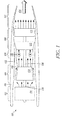
- FIG. 1 depicts a simplified cross section side view of an exemplary multi-spool turbofan gas turbine jet engine
- FIG. 2 depicts a cross section view of an embodiment of a combustor unit that may be used in an engine such as the engine of FIG. 1.
- FIG. 1 depicts an embodiment of an exemplary multi-spool gas turbine main propulsion engine 100.
- the engine 100 includes an intake section 102, a compressor section 104, a combustion section 106, a turbine section 108, and an exhaust section 112.
- the intake section 102 includes a fan 114, which is mounted in a fan case 116.
- the fan 114 draws air into the intake section 102 and accelerates it.
- a fraction of the accelerated air exhausted from the fan 114 is directed through a bypass section 118 disposed between an engine cowl 122 and a compressor 124, and generates propulsion thrust.
- the remaining fraction of air exhausted from the fan 114 is directed into the compressor section 104.
- the compressor section 104 may include one or more compressors 124, which raise the pressure of the air directed into it from the fan 114, and directs the compressed air into the combustion section 106. In the depicted embodiment, only a single compressor 124 is shown, though it will be appreciated that one or more additional compressors could be used.
- the combustion section 106 which includes a combustor unit 126, the compressed air is mixed with fuel supplied from a fuel source (not shown). The fuel/air mixture is combusted, generating high energy combusted gas that is then directed into the turbine section 108.
- the combustor unit 126 may be implemented as any one of numerous types of combustor units. However, as will be discussed in more detail further below, the combustor unit 126 is preferably implemented as a reverse flow combustor unit.
- the turbine section 108 includes one or more turbines.
- the turbine section 108 includes two turbines, a high pressure turbine 128, and a low pressure turbine 132, and more particularly, a single-stage high pressure turbine 128 and a multi-stage low pressure turbine 132.
- the propulsion engine 100 could be configured with more than this number of turbines. No matter the particular number of turbines, the combusted gas from the combustion section 106 expands through each turbine 128, 132, causing it to rotate. The gas is then exhausted through a propulsion nozzle 134 disposed in the exhaust section 112, generating additional propulsion thrust.
- each drives equipment in the main propulsion engine 100 via concentrically disposed shafts or spools.
- the high pressure turbine 128 drives the compressor 124 via a high pressure spool 136
- the low pressure turbine 132 drives the fan 114 via a low pressure spool 138.
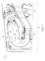
- FIG. 2 a cross section view of a particular embodiment of the reverse flow combustor unit 126 is depicted and will now be described in more detail.
- the combustor unit 126 is disposed radially outwardly of the single-stage high pressure turbine 128, and axially upstream of the multi-stage low pressure turbine 132.
- the combustor unit 126 preferably includes an annular liner assembly 140, a dome assembly 142, and a plurality of fuel injectors 144.
- the annular liner assembly 140 includes an inner annular liner 146 and an outer annular liner 148.
- the inner annular liner 146 surrounds the single-stage high pressure turbine 128.
- the outer annular liner 148 is preferably disposed radially outwardly of, and at least partially surrounds, the inner annular liner 146.
- the inner and outer annular liners 146, 148 have a plurality of non-illustrated openings for the flow of air therethrough.
- the combustor dome assembly 142 is coupled between the inner annular liner 146 and the outer annular liner 148 to define a combustion chamber 150.
- the combustion chamber 150 is fluidly coupled to receive the flow of compressed air supplied from the compressor section 104, and more particularly from the high pressure compressor 124 (not depicted in FIG. 2), and through the above-referenced openings in the inner and outer annular liners 146. 148.
- each straight fuel injector 144 has at least one fuel inlet 152 that is adapted to receive a flow of fuel, an outlet 154 that is in fluid communication with the combustion chamber 150, and a linear fuel passageway 156 extending therebetween. It will be appreciated by one of skill in the art that, in some embodiments, one or more of the fuel injectors 144 may have different characteristics than other fuel injectors 144. For example, one or more of the fuel injectors 144 may not have a linear fuel passageway 156.
- a mixture of fuel and air is supplied to the combustion chamber 150 via the fuel injector outlet 154, and is then ignited within the combustor chamber 150 by one or more igniters (not shown), generating combustion gas.
- the combustion gas then flows through a transition liner passageway 158, which directs it into the single-stage high pressure turbine 128.
- the gas exhausted from the single-stage high pressure turbine 128 is then directed into the multi-stage low pressure turbine 132.
- the single-stage high pressure turbine 128 is configured, upon receipt of the combustion gas, to rotate about a rotational axis 160.
- at least one, and preferably each of, the straight-shafted fuel injectors 144 when installed, have an axis of symmetry 162 that is not parallel to the rotational axis 160.
- the combustor dome assembly 142 has a substantially conical shape, about axis 160. This substantial conical shape in turn provides enhanced stiffness and structural integrity for the combustor dome assembly 142, which facilitates the use of the straight-shafted fuel injectors 144.
- the straight-shafted fuel injectors 144 are advantageous, for example in that they are easier and less expensive to manufacture, compared with their bent counterparts typically used in this type of combustor unit 126.
- the combustor unit 126 is preferably mounted within a combustor casing 164.
- the combustor casing 164 is disposed radially outwardly of, and at least partially surrounds, the outer annular liner 148.
- the combustor casing 164 and the outer annular liner 148 at least partially define a compressed air passageway 166 for the flow of compressed air from the high pressure compressor 124 to the combustor unit 126.
- the straight-shafted fuel injectors 144 are preferably coupled to the combustor casing 164, as well as to the combustor dome assembly 142.
- the combustor unit 126 may also include one or more flanges 168, such as bayonet flanges, or any one of numerous other types of flanges, for securing the straight-shafted fuel injectors 144 to the combustor unit 126 via, for example, a plurality of bolts 170.
- flanges 168 such as bayonet flanges, or any one of numerous other types of flanges
- mating threads 172 may be disposed on at least a portion of the combustor unit 126, for example on the combustor casing 164, and on the straight-shafted fuel injectors 144 to secure the straight-shafted fuel injectors 144 to the dome assembly 142.
- straight-shafted fuel injectors 144 can also be secured to the combustor unit 126 at various other regions on the combustor unit 126, and that any one of numerous mechanisms can be used for securing the straight-shafted fuel injectors 144 to the combustor unit 126.
Landscapes
- Engineering & Computer Science (AREA)
- Chemical & Material Sciences (AREA)
- Combustion & Propulsion (AREA)
- Mechanical Engineering (AREA)
- General Engineering & Computer Science (AREA)
- Structures Of Non-Positive Displacement Pumps (AREA)
- Turbine Rotor Nozzle Sealing (AREA)
Applications Claiming Priority (1)
| Application Number | Priority Date | Filing Date | Title |
|---|---|---|---|
| US11/408,662 US20070245710A1 (en) | 2006-04-21 | 2006-04-21 | Optimized configuration of a reverse flow combustion system for a gas turbine engine |
Publications (2)
| Publication Number | Publication Date |
|---|---|
| EP1847779A2 true EP1847779A2 (fr) | 2007-10-24 |
| EP1847779A3 EP1847779A3 (fr) | 2008-08-13 |
Family
ID=38283190
Family Applications (1)
| Application Number | Title | Priority Date | Filing Date |
|---|---|---|---|
| EP07106673A Withdrawn EP1847779A3 (fr) | 2006-04-21 | 2007-04-20 | Configuration optimisée d'un système de combustion à débit inverse pour turbine à gaz |
Country Status (4)
| Country | Link |
|---|---|
| US (1) | US20070245710A1 (fr) |
| EP (1) | EP1847779A3 (fr) |
| JP (1) | JP2007292075A (fr) |
| CA (1) | CA2585527A1 (fr) |
Families Citing this family (14)
| Publication number | Priority date | Publication date | Assignee | Title |
|---|---|---|---|---|
| US7506511B2 (en) * | 2003-12-23 | 2009-03-24 | Honeywell International Inc. | Reduced exhaust emissions gas turbine engine combustor |
| US20090199563A1 (en) * | 2008-02-07 | 2009-08-13 | Hamilton Sundstrand Corporation | Scalable pyrospin combustor |
| US8176725B2 (en) * | 2009-09-09 | 2012-05-15 | United Technologies Corporation | Reversed-flow core for a turbofan with a fan drive gear system |
| US8864492B2 (en) * | 2011-06-23 | 2014-10-21 | United Technologies Corporation | Reverse flow combustor duct attachment |
| FR2979139A1 (fr) * | 2011-08-16 | 2013-02-22 | Snecma | Chambre de combustion inversee conique pour turbomachine |
| US9222409B2 (en) | 2012-03-15 | 2015-12-29 | United Technologies Corporation | Aerospace engine with augmenting turbojet |
| US11286885B2 (en) | 2013-08-15 | 2022-03-29 | Raytheon Technologies Corporation | External core gas turbine engine assembly |
| US9989011B2 (en) | 2014-04-15 | 2018-06-05 | United Technologies Corporation | Reverse flow single spool core gas turbine engine |
| CN111075563A (zh) * | 2019-12-27 | 2020-04-28 | 至玥腾风科技集团有限公司 | 一种冷热电三联供微型燃气轮机设备 |
| US11603799B2 (en) * | 2020-12-22 | 2023-03-14 | General Electric Company | Combustor for a gas turbine engine |
| US11549437B2 (en) * | 2021-02-18 | 2023-01-10 | Honeywell International Inc. | Combustor for gas turbine engine and method of manufacture |
| CN113137639B (zh) * | 2021-04-25 | 2022-07-15 | 中国航发湖南动力机械研究所 | 涡桨发动机回流燃烧室及涡桨发动机 |
| US11859819B2 (en) | 2021-10-15 | 2024-01-02 | General Electric Company | Ceramic composite combustor dome and liners |
| US11959401B1 (en) | 2023-03-24 | 2024-04-16 | Honeywell International Inc. | Deswirl system for gas turbine engine |
Family Cites Families (31)
| Publication number | Priority date | Publication date | Assignee | Title |
|---|---|---|---|---|
| BE489359A (fr) * | 1944-10-05 | |||
| GB617977A (en) * | 1945-04-04 | 1949-02-15 | Lysholm Alf | Improvements in gas turbine power plants |
| US2611241A (en) * | 1946-03-19 | 1952-09-23 | Packard Motor Car Co | Power plant comprising a toroidal combustion chamber and an axial flow gas turbine with blade cooling passages therein forming a centrifugal air compressor |
| US2721445A (en) * | 1949-12-22 | 1955-10-25 | James V Giliberty | Aircraft propulsion plant of the propeller-jet turbine type |
| US2746246A (en) * | 1952-09-05 | 1956-05-22 | Valota Alessandro | Axial flow gas turbine |
| US3088279A (en) * | 1960-08-26 | 1963-05-07 | Gen Electric | Radial flow gas turbine power plant |
| FR1388005A (fr) * | 1963-12-09 | 1965-02-05 | Chambre de combustion de turbine à gaz | |
| GB1040390A (en) * | 1965-07-12 | 1966-08-24 | Rolls Royce | Gas turbine engine |
| US3447757A (en) * | 1967-02-28 | 1969-06-03 | Lucas Industries Ltd | Spray nozzles |
| US3703081A (en) * | 1970-11-20 | 1972-11-21 | Gen Electric | Gas turbine engine |
| US3671171A (en) * | 1970-11-27 | 1972-06-20 | Avco Corp | Annular combustors |
| US3691766A (en) * | 1970-12-16 | 1972-09-19 | Rolls Royce | Combustion chambers |
| US4046478A (en) * | 1971-03-02 | 1977-09-06 | Robert Bosch G.M.B.H. | Securing means for fuel injection nozzles |
| US3742703A (en) * | 1971-10-26 | 1973-07-03 | Avco Corp | Variable geometry combustor construction |
| US3971208A (en) * | 1974-04-01 | 1976-07-27 | The Garrett Corporation | Gas turbine fuel control |
| US3905191A (en) * | 1974-04-10 | 1975-09-16 | Avco Corp | Gas turbine engine with efficient annular bleed manifold |
| US3937013A (en) * | 1974-06-27 | 1976-02-10 | General Motors Corporation | By-pass jet engine with centrifugal flow compressor |
| US4083181A (en) * | 1976-06-14 | 1978-04-11 | The United States Of America As Represented By The Administrator Of The National Aeronautics And Space Administration | Gas turbine engine with recirculating bleed |
| DE2723546A1 (de) * | 1977-05-25 | 1978-11-30 | Motoren Turbinen Union | Brennkammer, insbesondere ringumkehrbrennkammer fuer gasturbinentriebwerke |
| US4195476A (en) * | 1978-04-27 | 1980-04-01 | General Motors Corporation | Combustor construction |
| US5237813A (en) * | 1992-08-21 | 1993-08-24 | Allied-Signal Inc. | Annular combustor with outer transition liner cooling |
| US5372008A (en) * | 1992-11-10 | 1994-12-13 | Solar Turbines Incorporated | Lean premix combustor system |
| US5323602A (en) * | 1993-05-06 | 1994-06-28 | Williams International Corporation | Fuel/air distribution and effusion cooling system for a turbine engine combustor burner |
| US5628193A (en) * | 1994-09-16 | 1997-05-13 | Alliedsignal Inc. | Combustor-to-turbine transition assembly |
| RU2190807C2 (ru) * | 1996-09-26 | 2002-10-10 | Сименсакциенгезелльшафт | Компонент теплозащитного экрана, через который проходит под давлением охлаждающая среда, и теплозащитный экран для компонента, через который проходит горячий газ |
| US5850732A (en) * | 1997-05-13 | 1998-12-22 | Capstone Turbine Corporation | Low emissions combustion system for a gas turbine engine |
| US6871488B2 (en) * | 2002-12-17 | 2005-03-29 | Pratt & Whitney Canada Corp. | Natural gas fuel nozzle for gas turbine engine |
| US7000406B2 (en) * | 2003-12-03 | 2006-02-21 | Pratt & Whitney Canada Corp. | Gas turbine combustor sliding joint |
| US7174717B2 (en) * | 2003-12-24 | 2007-02-13 | Pratt & Whitney Canada Corp. | Helical channel fuel distributor and method |
| US7302801B2 (en) * | 2004-04-19 | 2007-12-04 | Hamilton Sundstrand Corporation | Lean-staged pyrospin combustor |
| US7260936B2 (en) * | 2004-08-27 | 2007-08-28 | Pratt & Whitney Canada Corp. | Combustor having means for directing air into the combustion chamber in a spiral pattern |
-
2006
- 2006-04-21 US US11/408,662 patent/US20070245710A1/en not_active Abandoned
-
2007
- 2007-04-20 EP EP07106673A patent/EP1847779A3/fr not_active Withdrawn
- 2007-04-20 JP JP2007111693A patent/JP2007292075A/ja not_active Withdrawn
- 2007-04-20 CA CA002585527A patent/CA2585527A1/fr not_active Abandoned
Also Published As
| Publication number | Publication date |
|---|---|
| CA2585527A1 (fr) | 2007-10-21 |
| EP1847779A3 (fr) | 2008-08-13 |
| JP2007292075A (ja) | 2007-11-08 |
| US20070245710A1 (en) | 2007-10-25 |
Similar Documents
| Publication | Publication Date | Title |
|---|---|---|
| EP1847779A2 (fr) | Configuration optimisée d'un système de combustion à débit inverse pour turbine à gaz | |
| US7966821B2 (en) | Reduced exhaust emissions gas turbine engine combustor | |
| US7500364B2 (en) | System for coupling flow from a centrifugal compressor to an axial combustor for gas turbines | |
| EP2806217B1 (fr) | Moteurs à turbine à gaz avec ensembles d'injecteur de carburant | |
| EP2123863B1 (fr) | Prédiffuseur pour compresseur centrifuge | |
| JP4997018B2 (ja) | 一次燃料噴射器及び複数の二次燃料噴射ポートを有するガスタービンエンジン燃焼器のミキサ組立体のためのパイロットミキサ | |
| US10208628B2 (en) | Turbine engine designs for improved fine particle separation efficiency | |
| US11175045B2 (en) | Fuel nozzle for gas turbine engine combustor | |
| EP2481985B1 (fr) | Ensemble d'injecteur de carburant | |
| CN110691942B (zh) | 具有驱动器气流通路的用于燃气涡轮发动机的驻涡燃烧器 | |
| EP4206534B1 (fr) | Prémélangeur de carburant de turbine à gaz | |
| US11592182B1 (en) | Swirler ferrule plate having pressure drop purge passages | |
| US20170342912A1 (en) | Fuel delivery system for a gas turbine engine | |
| US20230266002A1 (en) | Coupling a fuel nozzle purge flow directly to a swirler | |
| US11994295B2 (en) | Multi pressure drop swirler ferrule plate | |
| US20140283525A1 (en) | Two-branch mixing passage and method to control combustor pulsations | |
| US7197881B2 (en) | Low loss flow limited feed duct | |
| KR20190126778A (ko) | 축방향으로 단계적인 연료 분사를 갖는 연소 시스템 | |
| EP4411237B1 (fr) | Injecteur avec disque pour moteur à turbine à gaz à hydrogène |
Legal Events
| Date | Code | Title | Description |
|---|---|---|---|
| PUAI | Public reference made under article 153(3) epc to a published international application that has entered the european phase |
Free format text: ORIGINAL CODE: 0009012 |
|
| AK | Designated contracting states |
Kind code of ref document: A2 Designated state(s): AT BE BG CH CY CZ DE DK EE ES FI FR GB GR HU IE IS IT LI LT LU LV MC MT NL PL PT RO SE SI SK TR |
|
| AX | Request for extension of the european patent |
Extension state: AL BA HR MK YU |
|
| PUAL | Search report despatched |
Free format text: ORIGINAL CODE: 0009013 |
|
| AK | Designated contracting states |
Kind code of ref document: A3 Designated state(s): AT BE BG CH CY CZ DE DK EE ES FI FR GB GR HU IE IS IT LI LT LU LV MC MT NL PL PT RO SE SI SK TR |
|
| AX | Request for extension of the european patent |
Extension state: AL BA HR MK RS |
|
| RIC1 | Information provided on ipc code assigned before grant |
Ipc: F23R 3/60 20060101ALI20080710BHEP Ipc: F23R 3/54 20060101AFI20070730BHEP |
|
| 17P | Request for examination filed |
Effective date: 20090206 |
|
| 17Q | First examination report despatched |
Effective date: 20090306 |
|
| AKX | Designation fees paid |
Designated state(s): FR |
|
| REG | Reference to a national code |
Ref country code: DE Ref legal event code: 8566 |
|
| STAA | Information on the status of an ep patent application or granted ep patent |
Free format text: STATUS: THE APPLICATION IS DEEMED TO BE WITHDRAWN |
|
| 18D | Application deemed to be withdrawn |
Effective date: 20090717 |