EP1847839A2 - Verfahren zur Erkennung eines Widerstandskurzschlusses, Modulsystem und Aufzeichnungsdatenträger für dieses Verfahren - Google Patents
Verfahren zur Erkennung eines Widerstandskurzschlusses, Modulsystem und Aufzeichnungsdatenträger für dieses Verfahren Download PDFInfo
- Publication number
- EP1847839A2 EP1847839A2 EP07290451A EP07290451A EP1847839A2 EP 1847839 A2 EP1847839 A2 EP 1847839A2 EP 07290451 A EP07290451 A EP 07290451A EP 07290451 A EP07290451 A EP 07290451A EP 1847839 A2 EP1847839 A2 EP 1847839A2
- Authority
- EP
- European Patent Office
- Prior art keywords
- motor
- phase
- resistive
- sensors
- short circuit
- Prior art date
- Legal status (The legal status is an assumption and is not a legal conclusion. Google has not performed a legal analysis and makes no representation as to the accuracy of the status listed.)
- Granted
Links
Images

Classifications
-
- G—PHYSICS
- G01—MEASURING; TESTING
- G01R—MEASURING ELECTRIC VARIABLES; MEASURING MAGNETIC VARIABLES
- G01R31/00—Arrangements for testing electric properties; Arrangements for locating electric faults; Arrangements for electrical testing characterised by what is being tested not provided for elsewhere
- G01R31/34—Testing dynamo-electric machines
- G01R31/343—Testing dynamo-electric machines in operation
-
- G—PHYSICS
- G01—MEASURING; TESTING
- G01R—MEASURING ELECTRIC VARIABLES; MEASURING MAGNETIC VARIABLES
- G01R31/00—Arrangements for testing electric properties; Arrangements for locating electric faults; Arrangements for electrical testing characterised by what is being tested not provided for elsewhere
- G01R31/50—Testing of electric apparatus, lines, cables or components for short-circuits, continuity, leakage current or incorrect line connections
- G01R31/52—Testing for short-circuits, leakage current or ground faults
Definitions
- the present invention relates to a method for detecting an impedance short circuit having a non-zero real part, a system, a module and a recording medium for this method.
- Some of these traction systems are also equipped with at least one resistive load connectable between each pair of phase conductors via at least one controllable switch.
- the resistive load is often used to dissipate the vehicle's braking energy or to attenuate overvoltages.
- An impedant short circuit is a short circuit that is established between two motor windings normally electrically isolated from each other.
- this short circuit has a certain impedance.
- the real part, that is to say the resistive part, of this impedance is greater than a few milliohms and generally greater than 10 m ⁇ .
- resistive short-circuit an impedant short circuit whose real part is non-zero, will be called "resistive short-circuit".
- the imaginary part of such a short circuit can be null or not.
- such a short resistive circuit may occur when windings of the same motor winding are short-circuited with one another or when windings of two different windings are short-circuited with each other.
- the solution 1) makes it possible to balance the currents in each of the phases of the motor and this despite the existence of the resistive short circuit. This cancels out or greatly reduces the current flowing through the resistive short circuit. The intensity of the current is therefore strictly the same in each of the phase conductors. No information on the existence of a resistive short circuit can be obtained from measurements of this balanced current.
- existing systems often also include at least one specific sensor dedicated to the detection of a motor fault such as a short circuit between windings of the motor.
- the aim of the invention is to satisfy this desire by proposing a method for detecting a resistive short-circuit that does not require the use of a sensor specifically dedicated to this use.
- the invention also relates to an information recording medium comprising instructions for performing the above screening method when these instructions are executed by an electronic computer.
- the subject of the invention is also a diagnostic module capable of being used in the above traction system, in which the diagnostic module is able to implement the above method of screening a patient. resistive short circuit.
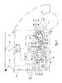
- FIG. 1 shows a vehicle 2 equipped with a traction system 4 capable of rotating the driving wheels of the vehicle 2.
- the vehicle 2 is a railway vehicle such as a train.
- the system 4 is supplied with DC voltage from a catenary 10. More precisely, the system 4 is connected to the catenary 10 by via a pantograph 12 and an input inductor 13 connected in series with a circuit breaker 14.
- the system 4 comprises a three-phase power source formed of a DC voltage supply bus connected to the input of a controllable three-phase inverter / rectifier 20.
- the power bus is here formed of two electrical conductors 22 and 24.
- the conductor 22 is electrically connected to an output of the circuit breaker 14 delivering the supply voltage.
- the electrical conductor 24 is connected to a reference potential such as ground.
- conductors 22 and 24 are electrically connected at one of their ends to DC voltage inputs 26 and 27 of the inverter / rectifier 20.
- the inverter / rectifier 20 comprises three AC voltage outputs 30, 31 and 32 respectively connected to phase conductors 34 to 36.
- This inverter / rectifier 20 is able to transform the DC voltage present between the conductors 22 and 24 into an AC voltage delivered on the outputs 30 to 32 and vice versa.
- the inverter / rectifier 20 is a conventional inverter / rectifier equipped with controllable switches such as IGBT (Insulated Gate Bipolar Transistor) transistors.
- IGBT Insulated Gate Bipolar Transistor
- this inverter / rectifier 20 has three branches connected in parallel, each branch comprises two controllable switches connected in series across which terminals are connected freewheel in antiparallel position.
- Each conductor 34 to 36 supplies stator windings of a respective phase of a three-phase motor 38 with permanent magnets.
- stator windings 40 to 42 fed respectively by the conductors 34 to 36 are shown in FIG. 1. These stator windings are capable of producing a magnetic field of excitation suitable for driving in rotation a rotor 44 equipped with permanent magnets. To simplify FIG. 1, only three permanent magnets 46 to 48 are shown.
- the internal resistance of the motor 38 is defined as the resistance of all the windings of a phase. In the case of a star-mounted motor, this resistance can be measured by measuring the resistance of the motor taken between two terminals of connection of the phase conductors and dividing the measured resistance by two, so as to obtain the resistance of the coils of a single phase.
- the R int value of the internal resistance of a polyphase motor is between 5 m ⁇ and 100 m ⁇ .
- the value R int of the internal resistance of the motor 38 is equal to 40 m ⁇ .
- the rotor 44 rotates a shaft 50 which itself drives in rotation, by means of mechanisms not shown, the drive wheels of the vehicle 2.
- controllable contactors 52 to 54 make it possible to electrically disconnect the phase conductors 34 to 36 from the coils of the motor 38.
- a variable resistive load 60 is connectable at the input of the inverter / rectifier 20 between the conductors 22 and 24. It will be noted that connecting a resistive load between the conductors 22 and 24 is, from an electrical point of view, connected to a load resistive between each pair of phase conductors 34 to 36.
- the load 60 is designed so that the value of its resistive portion connected between each pair of phase conductors is between R int and 200000.R int , where the symbol ". "Means multiplication.
- the load 60 is designed so that the value of its resistive portion connected between each pair of phase conductors can vary between R int and 20000.R int see even from R int to 2000.R int .
- the resistive portion connected between each pair of phase conductors can vary between 40 m ⁇ and 8 ⁇ .
- this load 60 is also intended to dissipate the braking energy when the motor 38 operates as a current generator for braking the vehicle 2.
- the load 60 comprises a resistor 62 of constant value R H and a rheostatic chopper 64.
- R H is here equal to 2 3 ⁇ R int .
- Resistance 62 is directly connected by one of its ends to the conductor 24 and the other of its ends to the conductor 22 via the chopper 64.
- the chopper 64 allows, when activated, to connect the load 60 to the conductor 22 and when deactivated, electrically isolating the load 60 from the conductor 22. In addition, when the chopper is energized, it allows the value of the resistive portion of the load 60 to be varied by chopping the current through the resistance 62.
- This chopper 64 here comprises a controllable switch 66 connected in series with a diode 68 via a common point 70.
- the switch 68 is here produced using an IGBT transistor 72 whose collector is directly connected to the conductor 22 and the emitter at the point 70.
- a freewheeling diode 74 is connected in antiparallel position to the terminals of the transistor 72 .
- the cathode of the diode 68 is connected to the point 70 while its anode is directly connected to the conductor 24.
- Midpoint 70 is connected to resistor 62.
- the switching frequency f c of the switch 66 is between 50 Hz and 10 kHz.
- the frequency f c is equal to 400 Hz.
- the opening rate T X of the switch 66 is controllable.
- the opening rate T X can vary between 0.005 and 1.
- a filtering capacitor 78 is permanently connected between the conductors 22 and 24.
- the system 4 comprises a sensor 80 dedicated solely to the detection of a motor failure 38.
- the sensor 80 is able to measure characteristics representative of the operation of the motor 38. These characteristics make it possible to detect an engine failure even when the latter rotates the drive wheels.
- the sensor 80 is, for example, a vibration detector of the motor 38.
- the system 4 is also equipped with current sensors capable of measuring the current in each of the phase conductors 34 to 36.
- current sensors capable of measuring the current in each of the phase conductors 34 to 36.
- only two current sensors 84 and 86 associated respectively with the conductors 34 and 35 are used. Indeed, the value of the current in the conductor 36 can be deduced from the measurements made by the sensors 84 and 86.
- a control module 88 is able to start from the current measurements made by the sensors 84 and 86 to control the torque of the shaft 50 of the motor 38. More specifically, for this purpose, the control module 88 controls the inverter. rectifier 20.
- the module 88 is also able to control the contactors 52 to 54 as well as the chopper 64.
- the system 4 comprises a diagnostic module 90 able to detect a motor failure 38 from the measurements of the sensor 80 and also to detect a resistive short-circuit between windings and windings of this motor from the current measurements taken. by sensors 84 and 86.
- the module 90 is able to control the inverter / rectifier 20 and the chopper 64.
- the modules 88 and 90 are, for example, made using a programmable electronic calculator 94 able to execute the instructions stored in a memory 96.
- the memory 96 includes instructions for carrying out the method of FIG. 2 when these are executed by the computer 94.
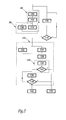
- system 4 does not fail. Under these conditions, the propulsion phases 98 of the vehicle 2 are alternated with the braking phases 99 of the vehicle.
- the sensors 84 and 86 measure, during a step 100, the current in the phase conductors 34 and 35 and transmit these measurements to the control module 88. Then, during a step 102 , the module 88 controls the inverter / rectifier 20 so as to adjust the traction torque exerted by the motor 38 as a function of the measured currents and a torque setpoint.
- the module 88 controls, during a step 104, the inverter / rectifier 20 so that it operates as a voltage rectifier and the motor 38 operates as a current generator phase.
- the module 88 controls the chopper 64 to adjust the value of the resistive portion of the load 60, so that it dissipates the energy generated by the motor 38 when braking the vehicle 2.
- the sensor 80 In parallel with the phases 98 and 99, during a step 108, the sensor 80 permanently measures the characteristics of the motor 38 from which a failure of this motor can be detected. These measurements are analyzed in real time, during a step 110, by the diagnostic module 90. If from these measurements, the module 90 does not detect a failure of the motor 38, then no particular action is taken and the phases 98 and 99 continue to run normally. In this case, at the end of step 110, the process returns to step 108.
- step 110 the module 90 detects that there is a motor failure 38, then the phases 98 and 89 are interrupted and the process continues with a phase 120 for the detection of a resistive short-circuit between windings of motor windings 38.
- the module 90 controls the inverter / rectifier 20 to operate the motor 38 as a three-phase generator and the inverter / rectifier as a three-phase rectifier. More specifically, during step 122, the module 90 keeps open the IGBT transistors of the inverter / rectifier 20 so that it acts as a diode rectifier bridge.
- the module 90 controls the activation of the chopper 64 to connect the load 60 between the conductors 22 and 24.
- the opening rate T X of the chopper 64 goes directly from the value 0 to the value 1 so that the value of the resistive portion of the load 60 is minimal.
- the motor 38 brakes the vehicle 2.
- virtually all of the current generated by the motor 38 passes through the phase conductors because the value of the load 60 connected between the conductors 22 and 24 is substantially equal to R int . Under these conditions, the aggravation of the engine failure is limited.
- the sensors 84 and 86 measure the current flowing in the phase conductors 34 and 35 and transmit these measurements to the module 90.
- the module 90 tries to detect the existence of a resistive short circuit. More precisely, during step 128, the module 90 determines, during an operation 130, the power of the fundamentals of all the phase currents from the measurements made by the sensors 84 and 86. Here, these fundamentals have a frequency equal to the stator frequency of the motor 38. Then, during an operation 132, the powers thus determined are compared two by two.
- the module 90 controls the chopper 64 to increase the value of the resistive portion of the load 60 by a predetermined pitch. For example, in step 130, the module 90 decreases the opening rate T X of the rheostatic chopper 64 by a predetermined pitch. This predetermined step is, for example, equal to 0.05.
- step 138 during which the module 90 again tries to detect the existence of a resistive short circuit.
- This step 138 is, for example, identical to step 128. If not, the method returns to step 136.
- the module 90 progressively increases the value of the resistive portion of the load 60 until this is sufficient for a substantial portion of the current generated by the motor 38 to flow in the phase conductors while another substantial portion of the current flows through the resistive short circuit.
- the part of the current is called “substantial” since it allows the detection of a short circuit from the currents measured by the sensors 84 and 86 by applying a detection method such as that described with regard to the step 128.
- the difference between the powers of the current fundamentals exceeds, for example, a predetermined threshold, which makes it possible to establish the existence of the resistive short circuit.
- a predetermined threshold which makes it possible to establish the existence of the resistive short circuit.
- phase 120 ends and continues with a step 140 during which the driver of the vehicle 2 is informed of the existence of a resistive short circuit.
- the process stops, when a step 142, and the existence of a resistive short circuit is not confirmed.
- the module 90 since the sensors 84 and 86 are placed upstream of the contactors 52 to 54, the module 90 also makes it possible to detect a short-circuit between these contactors 52 to 54 and a short-circuit. resistive circuit between the phase conductors connecting these conductors 52 to 54 to connection terminals of the motor 38.
- the module 90 is also able to detect a failure of the inverter / rectifier 20 since the measured current by the sensors 84 and 86 also passes through the inverter / rectifier 20 before reaching the load 60.
- FIG. 3 represents another embodiment of a system 150 of electric traction of the vehicle 2.
- the elements already described with reference to FIG. 1 bear the same numerical references.
- the system 150 is identical to the system 4 except that the resistive load 60 is replaced by a three-phase variable resistive load 152 connected between the phase conductors 34 to 36.
- the load 152 is formed of three parallel branches connected at one of their ends to a common point 153. The other ends of these branches are respectively connected to the conductors 34, 35 and 36. Each of these branches has a resistance, respectively 154 at 156, directly connected on one side to the common point 152 and on the other side to the phase conductor via a controllable rheostatic chopper 160.
- the chopper 160 is controllable by the diagnostic module 90.
- the value of the resistances 154 to 156 is constant.
- the value of the resistors 154 to 156 is chosen equal to R int so that the value of the resistive portion of the load 152 on each of the branches can vary between R int and 2000.R int .
- the module 90 adjusts the value of the resistive portion of the load 152 so that a substantial portion of the current generated by the motor 38 passes through the resistive short circuit and another substantial portion flows in the phase conductors. So, as in the In system 4, the current sensors 84 and 86 can be used to detect the existence of a resistive short circuit. However, in this embodiment, the current flowing in the phase conductors does not pass through the inverter / rectifier 20 so that in this embodiment failure of this inverter / rectifier 20 can not be detected.
- variable resistive portion of the resistive load can be made from a varistor whose value varies as a function of the voltage applied across its terminals.
- the variable resistive portion can also be realized using a DC-DC converter.
- the resistive portion used to circulate a substantial portion of the current in the phase conductors 34 to 36 is the same as that used during a dynamic braking to dissipate the energy generated by the motor 38.
- the value of the resistive portion is not adjusted in the same way. Indeed, in case of dynamic braking, the value of the resistor 62 is adjusted so as to adequately dissipate the energy generated by the motor 38 during braking.
- this same resistor is used to implement the screening method, its value is adjusted so that a substantial portion of the three-phase current generated by the motor 38 flows in the phase conductors 34 to 36 so that from of measurements of this current, the module 90 can detect the existence of this resistive short circuit.
- a clipping resistor connected in parallel between the conductors 22 and 24 is used during the execution of the method of FIG. In normal operation of the traction system, this clipping resistor has the function of clipping the overvoltages which can appear between the conductors 22 and 24.
- the system 2 has been described in the particular case where the motor 38 is a permanent magnet motor. However, the method of FIG. 2 also applies to a traction system in which the traction motor is a synchronous synchronous polyphase motor, that is to say having coils both at the stator and at the rotor.
- variable load 60 and the variable load 152 may be replaced by loads whose value of the resistive portion is constant.
- the value of the resistive portion of this load is predetermined in advance by simulation or experimentally so that at a given speed of the vehicle 2 it allows in most cases of resistive short circuits to a substantial part the current generated by the motor to flow in the phase conductors while another substantial part through the resistive short circuit.
- the resistive short-circuit can be detected by other methods than that of comparing the power of the fundamentals of the currents measured.
- the screening method described herein can be applied to traction systems other than those used in a vehicle.
- the senor 80 may be omitted.
- the method of detection of a resistive short circuit is, for example, triggered at the start of the traction system.
- the screening method can also be triggered if an overcurrent is detected using sensors 84 and 86.
Landscapes
- Physics & Mathematics (AREA)
- General Physics & Mathematics (AREA)
- Electric Propulsion And Braking For Vehicles (AREA)
- Tests Of Circuit Breakers, Generators, And Electric Motors (AREA)
- Hybrid Electric Vehicles (AREA)
- Analysing Materials By The Use Of Radiation (AREA)
- Testing Or Measuring Of Semiconductors Or The Like (AREA)
- Control Of Ac Motors In General (AREA)
- Testing Of Short-Circuits, Discontinuities, Leakage, Or Incorrect Line Connections (AREA)
- Control Of Voltage And Current In General (AREA)
Applications Claiming Priority (1)
| Application Number | Priority Date | Filing Date | Title |
|---|---|---|---|
| FR0603560A FR2900241B1 (fr) | 2006-04-21 | 2006-04-21 | Procede de depistage d'un court-circuit resistif, systeme, module et support d'enregistrement pour ce procede |
Publications (3)
| Publication Number | Publication Date |
|---|---|
| EP1847839A2 true EP1847839A2 (de) | 2007-10-24 |
| EP1847839A3 EP1847839A3 (de) | 2011-03-09 |
| EP1847839B1 EP1847839B1 (de) | 2012-04-04 |
Family
ID=37663207
Family Applications (1)
| Application Number | Title | Priority Date | Filing Date |
|---|---|---|---|
| EP07290451A Not-in-force EP1847839B1 (de) | 2006-04-21 | 2007-04-12 | Verfahren zur Erkennung eines Widerstandskurzschlusses, System, Modul und Aufzeichnungsdatenträger für dieses Verfahren |
Country Status (7)
| Country | Link |
|---|---|
| EP (1) | EP1847839B1 (de) |
| JP (1) | JP2007292761A (de) |
| CN (1) | CN101059552B (de) |
| AT (1) | ATE552509T1 (de) |
| AU (1) | AU2007201678B2 (de) |
| ES (1) | ES2383543T3 (de) |
| FR (1) | FR2900241B1 (de) |
Cited By (1)
| Publication number | Priority date | Publication date | Assignee | Title |
|---|---|---|---|---|
| US10153633B2 (en) | 2014-09-24 | 2018-12-11 | Bombardier Transportation Gmbh | Method and device for monitoring an electrical network in a rail vehicle, and rail vehicle |
Families Citing this family (8)
| Publication number | Priority date | Publication date | Assignee | Title |
|---|---|---|---|---|
| FR2939244B1 (fr) * | 2008-12-03 | 2012-08-17 | Renault Sas | Boitier d'interconnexion pour vehicule automobile |
| RU2392632C1 (ru) * | 2008-12-10 | 2010-06-20 | Валерий Николаевич Денисов | Способ диагностики электрических двигателей с фазным ротором |
| EP2418411B1 (de) | 2009-04-01 | 2016-01-27 | Nissan Motor Co., Ltd. | Aufbau und herstellungsverfahren für einen druckbehälter |
| CN102012471B (zh) * | 2010-04-14 | 2014-10-08 | 深圳市英威腾电气股份有限公司 | 变频器输出对地短路检测方法及装置 |
| JP2015223050A (ja) * | 2014-05-23 | 2015-12-10 | ファナック株式会社 | インバータ及び動力線の故障検出機能を備えたモータ駆動装置 |
| JP6564470B2 (ja) * | 2015-12-09 | 2019-08-21 | 川崎重工業株式会社 | 鉄道車両用制御装置、列車編成および主電動機制御方法 |
| DK3480610T3 (da) * | 2017-11-07 | 2020-06-22 | Siemens Gamesa Renewable Energy As | Diagnosticering af et viklingssæt af en stator |
| KR102423301B1 (ko) * | 2017-12-11 | 2022-07-19 | 주식회사 엘지에너지솔루션 | 단락 방지 장치 및 방법 |
Family Cites Families (6)
| Publication number | Priority date | Publication date | Assignee | Title |
|---|---|---|---|---|
| JPH07288999A (ja) * | 1994-04-13 | 1995-10-31 | Nissan Motor Co Ltd | ステップモータの制御装置 |
| JP3473779B2 (ja) * | 1994-07-14 | 2003-12-08 | 株式会社安川電機 | 電流検出器の故障検出方法 |
| JP3473188B2 (ja) * | 1995-06-21 | 2003-12-02 | 松下電器産業株式会社 | インバータ装置 |
| JP3734236B2 (ja) * | 1997-12-10 | 2006-01-11 | サンデン株式会社 | 電気自動車用空調装置の電源入力回路 |
| AU6220100A (en) * | 1999-07-20 | 2001-02-05 | General Electric Company | Short circuit detection method, apparatus and motor drive incorporating the same |
| JP3954265B2 (ja) * | 2000-02-28 | 2007-08-08 | 株式会社東芝 | 車両用電力変換装置 |
-
2006
- 2006-04-21 FR FR0603560A patent/FR2900241B1/fr not_active Expired - Fee Related
-
2007
- 2007-04-12 EP EP07290451A patent/EP1847839B1/de not_active Not-in-force
- 2007-04-12 AT AT07290451T patent/ATE552509T1/de active
- 2007-04-12 ES ES07290451T patent/ES2383543T3/es active Active
- 2007-04-16 AU AU2007201678A patent/AU2007201678B2/en not_active Ceased
- 2007-04-20 CN CN2007101053805A patent/CN101059552B/zh not_active Expired - Fee Related
- 2007-04-23 JP JP2007112528A patent/JP2007292761A/ja active Pending
Cited By (1)
| Publication number | Priority date | Publication date | Assignee | Title |
|---|---|---|---|---|
| US10153633B2 (en) | 2014-09-24 | 2018-12-11 | Bombardier Transportation Gmbh | Method and device for monitoring an electrical network in a rail vehicle, and rail vehicle |
Also Published As
| Publication number | Publication date |
|---|---|
| ATE552509T1 (de) | 2012-04-15 |
| CN101059552B (zh) | 2012-03-28 |
| AU2007201678A1 (en) | 2007-11-08 |
| EP1847839A3 (de) | 2011-03-09 |
| JP2007292761A (ja) | 2007-11-08 |
| FR2900241B1 (fr) | 2008-07-11 |
| FR2900241A1 (fr) | 2007-10-26 |
| AU2007201678B2 (en) | 2011-07-07 |
| CN101059552A (zh) | 2007-10-24 |
| ES2383543T3 (es) | 2012-06-22 |
| EP1847839B1 (de) | 2012-04-04 |
Similar Documents
| Publication | Publication Date | Title |
|---|---|---|
| EP1847839B1 (de) | Verfahren zur Erkennung eines Widerstandskurzschlusses, System, Modul und Aufzeichnungsdatenträger für dieses Verfahren | |
| EP3308177B1 (de) | Elektrisches system mit einer schaltung zum erfassen eines elektrischen isolationsfehlers | |
| EP2820733B1 (de) | Feststellen von leckströmen mit gleichstromanteil in einem fahrzeug | |
| FR2778799A1 (fr) | Systeme de pilotage pour un moteur electrique a excitation permanente a au moins une phase | |
| FR2962270A1 (fr) | Machine électrique tournante améliorée pour assurer une protection contre les coupures d'alimentation électrique | |
| EP2033835A2 (de) | Sicherheitsvorrichtung zur Erfassung von Mängeln einer elektrischen Bremse und zur Weiterschaltung auf eine Sicherheitsbremse | |
| FR2825061A1 (fr) | Appareil electrique de direction assistee | |
| FR2894735A1 (fr) | Generateur-moteur synchrone a enroulement de champ | |
| EP1020019A1 (de) | Gerät und verfahren zur steuerung eines synchronmotors mit permanentmagnet | |
| EP1974455B1 (de) | Vorrichtung zur steuerung einer polyphasen-rotationsmaschine | |
| FR3001039A1 (fr) | Procede de detection d'un defaut electrique d'un dispositif de generateur et moyens pour sa mise en oeuvre | |
| FR2965124A1 (fr) | Rotary electric machine for vehicle | |
| WO2019162622A1 (fr) | Procédé de compensation d'un couple frein lors d'une défaillance de type court-circuit dans l'onduleur d'alimentation d'un moteur d'assistance | |
| FR2902739A1 (fr) | Dispositif de direction assistee | |
| EP2400659B1 (de) | Elektrische Vorrichtung, die einen Wechselstrommotor und einen Steuerumrichter umfasst, sowie ein Verfahren zur Messung der elektromotorischen Kraft dieser Vorrichtung | |
| FR2900517A1 (fr) | Appareil de commande de moteur | |
| EP2870018B1 (de) | Verfahren zur steuerung eines antriebsstranges und entsprechendes system | |
| WO2018158040A1 (fr) | Procede de commande d'un chargeur embarque de batterie automobile, connecte a un reseau d'alimentation electrique monophase ou triphase | |
| FR2908247A1 (fr) | Dispositif de commande d'alternateur pour vehicule | |
| WO2018050991A1 (fr) | Procédé d'alimentation d'une charge inductive | |
| FR2923331B1 (fr) | Appareil electrique rotatif pour automobile | |
| FR2898441A1 (fr) | Procede de parametrage d'un convertisseur et convertisseur mettant en oeuvre le procede | |
| EP4199345A1 (de) | Vorrichtung und verfahren zur überwachung eines elektrischen energiewandlers, zugehöriges elektrisches energieumwandlungssystem | |
| WO2020084128A1 (fr) | Procédé d'alimentation d'une charge inductive | |
| EP1686682A1 (de) | Verfahren und System zur begrenzung des Ausgangsstroms für einen V/f Umrichter- |
Legal Events
| Date | Code | Title | Description |
|---|---|---|---|
| PUAI | Public reference made under article 153(3) epc to a published international application that has entered the european phase |
Free format text: ORIGINAL CODE: 0009012 |
|
| AK | Designated contracting states |
Kind code of ref document: A2 Designated state(s): AT BE BG CH CY CZ DE DK EE ES FI FR GB GR HU IE IS IT LI LT LU LV MC MT NL PL PT RO SE SI SK TR |
|
| AX | Request for extension of the european patent |
Extension state: AL BA HR MK YU |
|
| PUAL | Search report despatched |
Free format text: ORIGINAL CODE: 0009013 |
|
| AK | Designated contracting states |
Kind code of ref document: A3 Designated state(s): AT BE BG CH CY CZ DE DK EE ES FI FR GB GR HU IE IS IT LI LT LU LV MC MT NL PL PT RO SE SI SK TR |
|
| AX | Request for extension of the european patent |
Extension state: AL BA HR MK RS |
|
| 17P | Request for examination filed |
Effective date: 20110909 |
|
| GRAP | Despatch of communication of intention to grant a patent |
Free format text: ORIGINAL CODE: EPIDOSNIGR1 |
|
| AKX | Designation fees paid |
Designated state(s): AT BE BG CH CY CZ DE DK EE ES FI FR GB GR HU IE IS IT LI LT LU LV MC MT NL PL PT RO SE SI SK TR |
|
| GRAS | Grant fee paid |
Free format text: ORIGINAL CODE: EPIDOSNIGR3 |
|
| GRAA | (expected) grant |
Free format text: ORIGINAL CODE: 0009210 |
|
| AK | Designated contracting states |
Kind code of ref document: B1 Designated state(s): AT BE BG CH CY CZ DE DK EE ES FI FR GB GR HU IE IS IT LI LT LU LV MC MT NL PL PT RO SE SI SK TR |
|
| REG | Reference to a national code |
Ref country code: GB Ref legal event code: FG4D Free format text: NOT ENGLISH |
|
| REG | Reference to a national code |
Ref country code: DE Ref legal event code: R081 Ref document number: 602007021731 Country of ref document: DE Owner name: ALSTOM TRANSPORT TECHNOLOGIES, FR Free format text: FORMER OWNER: ALSTOM TRANSPORT S.A., LEVALLOIS-PERRET, FR |
|
| REG | Reference to a national code |
Ref country code: CH Ref legal event code: EP |
|
| REG | Reference to a national code |
Ref country code: AT Ref legal event code: REF Ref document number: 552509 Country of ref document: AT Kind code of ref document: T Effective date: 20120415 |
|
| REG | Reference to a national code |
Ref country code: IE Ref legal event code: FG4D Free format text: LANGUAGE OF EP DOCUMENT: FRENCH |
|
| REG | Reference to a national code |
Ref country code: DE Ref legal event code: R096 Ref document number: 602007021731 Country of ref document: DE Effective date: 20120524 |
|
| REG | Reference to a national code |
Ref country code: ES Ref legal event code: FG2A Ref document number: 2383543 Country of ref document: ES Kind code of ref document: T3 Effective date: 20120622 |
|
| REG | Reference to a national code |
Ref country code: NL Ref legal event code: T3 |
|
| REG | Reference to a national code |
Ref country code: SE Ref legal event code: TRGR |
|
| LTIE | Lt: invalidation of european patent or patent extension |
Effective date: 20120404 |
|
| PG25 | Lapsed in a contracting state [announced via postgrant information from national office to epo] |
Ref country code: PL Free format text: LAPSE BECAUSE OF FAILURE TO SUBMIT A TRANSLATION OF THE DESCRIPTION OR TO PAY THE FEE WITHIN THE PRESCRIBED TIME-LIMIT Effective date: 20120404 Ref country code: CY Free format text: LAPSE BECAUSE OF FAILURE TO SUBMIT A TRANSLATION OF THE DESCRIPTION OR TO PAY THE FEE WITHIN THE PRESCRIBED TIME-LIMIT Effective date: 20120404 Ref country code: IS Free format text: LAPSE BECAUSE OF FAILURE TO SUBMIT A TRANSLATION OF THE DESCRIPTION OR TO PAY THE FEE WITHIN THE PRESCRIBED TIME-LIMIT Effective date: 20120804 Ref country code: FI Free format text: LAPSE BECAUSE OF FAILURE TO SUBMIT A TRANSLATION OF THE DESCRIPTION OR TO PAY THE FEE WITHIN THE PRESCRIBED TIME-LIMIT Effective date: 20120404 Ref country code: LT Free format text: LAPSE BECAUSE OF FAILURE TO SUBMIT A TRANSLATION OF THE DESCRIPTION OR TO PAY THE FEE WITHIN THE PRESCRIBED TIME-LIMIT Effective date: 20120404 Ref country code: SI Free format text: LAPSE BECAUSE OF FAILURE TO SUBMIT A TRANSLATION OF THE DESCRIPTION OR TO PAY THE FEE WITHIN THE PRESCRIBED TIME-LIMIT Effective date: 20120404 |
|
| PG25 | Lapsed in a contracting state [announced via postgrant information from national office to epo] |
Ref country code: LV Free format text: LAPSE BECAUSE OF FAILURE TO SUBMIT A TRANSLATION OF THE DESCRIPTION OR TO PAY THE FEE WITHIN THE PRESCRIBED TIME-LIMIT Effective date: 20120404 Ref country code: MC Free format text: LAPSE BECAUSE OF NON-PAYMENT OF DUE FEES Effective date: 20120430 Ref country code: GR Free format text: LAPSE BECAUSE OF FAILURE TO SUBMIT A TRANSLATION OF THE DESCRIPTION OR TO PAY THE FEE WITHIN THE PRESCRIBED TIME-LIMIT Effective date: 20120705 Ref country code: PT Free format text: LAPSE BECAUSE OF FAILURE TO SUBMIT A TRANSLATION OF THE DESCRIPTION OR TO PAY THE FEE WITHIN THE PRESCRIBED TIME-LIMIT Effective date: 20120806 |
|
| REG | Reference to a national code |
Ref country code: IE Ref legal event code: MM4A |
|
| PG25 | Lapsed in a contracting state [announced via postgrant information from national office to epo] |
Ref country code: IE Free format text: LAPSE BECAUSE OF NON-PAYMENT OF DUE FEES Effective date: 20120412 Ref country code: SK Free format text: LAPSE BECAUSE OF FAILURE TO SUBMIT A TRANSLATION OF THE DESCRIPTION OR TO PAY THE FEE WITHIN THE PRESCRIBED TIME-LIMIT Effective date: 20120404 Ref country code: DK Free format text: LAPSE BECAUSE OF FAILURE TO SUBMIT A TRANSLATION OF THE DESCRIPTION OR TO PAY THE FEE WITHIN THE PRESCRIBED TIME-LIMIT Effective date: 20120404 Ref country code: EE Free format text: LAPSE BECAUSE OF FAILURE TO SUBMIT A TRANSLATION OF THE DESCRIPTION OR TO PAY THE FEE WITHIN THE PRESCRIBED TIME-LIMIT Effective date: 20120404 Ref country code: RO Free format text: LAPSE BECAUSE OF FAILURE TO SUBMIT A TRANSLATION OF THE DESCRIPTION OR TO PAY THE FEE WITHIN THE PRESCRIBED TIME-LIMIT Effective date: 20120404 |
|
| PLBE | No opposition filed within time limit |
Free format text: ORIGINAL CODE: 0009261 |
|
| STAA | Information on the status of an ep patent application or granted ep patent |
Free format text: STATUS: NO OPPOSITION FILED WITHIN TIME LIMIT |
|
| 26N | No opposition filed |
Effective date: 20130107 |
|
| REG | Reference to a national code |
Ref country code: DE Ref legal event code: R097 Ref document number: 602007021731 Country of ref document: DE Effective date: 20130107 |
|
| PG25 | Lapsed in a contracting state [announced via postgrant information from national office to epo] |
Ref country code: MT Free format text: LAPSE BECAUSE OF FAILURE TO SUBMIT A TRANSLATION OF THE DESCRIPTION OR TO PAY THE FEE WITHIN THE PRESCRIBED TIME-LIMIT Effective date: 20120404 Ref country code: BG Free format text: LAPSE BECAUSE OF FAILURE TO SUBMIT A TRANSLATION OF THE DESCRIPTION OR TO PAY THE FEE WITHIN THE PRESCRIBED TIME-LIMIT Effective date: 20120704 |
|
| PG25 | Lapsed in a contracting state [announced via postgrant information from national office to epo] |
Ref country code: TR Free format text: LAPSE BECAUSE OF FAILURE TO SUBMIT A TRANSLATION OF THE DESCRIPTION OR TO PAY THE FEE WITHIN THE PRESCRIBED TIME-LIMIT Effective date: 20120404 |
|
| PG25 | Lapsed in a contracting state [announced via postgrant information from national office to epo] |
Ref country code: LU Free format text: LAPSE BECAUSE OF NON-PAYMENT OF DUE FEES Effective date: 20120412 |
|
| PG25 | Lapsed in a contracting state [announced via postgrant information from national office to epo] |
Ref country code: HU Free format text: LAPSE BECAUSE OF FAILURE TO SUBMIT A TRANSLATION OF THE DESCRIPTION OR TO PAY THE FEE WITHIN THE PRESCRIBED TIME-LIMIT Effective date: 20070412 |
|
| REG | Reference to a national code |
Ref country code: FR Ref legal event code: TP Owner name: ALSTOM TRANSPORT TECHNOLOGIES, FR Effective date: 20141209 |
|
| REG | Reference to a national code |
Ref country code: CH Ref legal event code: PUE Owner name: ALSTOM TRANSPORT TECHNOLOGIES, FR Free format text: FORMER OWNER: ALSTOM TRANSPORT SA, FR |
|
| REG | Reference to a national code |
Ref country code: DE Ref legal event code: R081 Ref document number: 602007021731 Country of ref document: DE Owner name: ALSTOM TRANSPORT TECHNOLOGIES, FR Free format text: FORMER OWNER: ALSTOM TRANSPORT SA, LEVALLOIS-PERRET, FR |
|
| REG | Reference to a national code |
Ref country code: GB Ref legal event code: 732E Free format text: REGISTERED BETWEEN 20151119 AND 20151125 |
|
| REG | Reference to a national code |
Ref country code: NL Ref legal event code: PD Owner name: ALSTOM TRANSPORT TECHNOLOGIES; FR Free format text: DETAILS ASSIGNMENT: VERANDERING VAN EIGENAAR(S), OVERDRACHT; FORMER OWNER NAME: ALSTOM TRANSPORT SA Effective date: 20150904 |
|
| REG | Reference to a national code |
Ref country code: FR Ref legal event code: PLFP Year of fee payment: 10 |
|
| REG | Reference to a national code |
Ref country code: FR Ref legal event code: PLFP Year of fee payment: 11 |
|
| REG | Reference to a national code |
Ref country code: DE Ref legal event code: R081 Ref document number: 602007021731 Country of ref document: DE Owner name: ALSTOM TRANSPORT TECHNOLOGIES, FR Free format text: FORMER OWNER: ALSTOM TRANSPORT TECHNOLOGIES, LEVALLOIS-PERRET, FR |
|
| REG | Reference to a national code |
Ref country code: CH Ref legal event code: NV Representative=s name: BUGNION S.A., CH Ref country code: CH Ref legal event code: PCOW Free format text: NEW ADDRESS: 48 RUE ALBERT DHALENNE, 93400 SAINT-OUEN (FR) |
|
| REG | Reference to a national code |
Ref country code: FR Ref legal event code: CA Effective date: 20180103 |
|
| REG | Reference to a national code |
Ref country code: AT Ref legal event code: PC Ref document number: 552509 Country of ref document: AT Kind code of ref document: T Owner name: ALSTOM TRANSPORT TECHNOLOGIES, FR Effective date: 20180220 |
|
| REG | Reference to a national code |
Ref country code: FR Ref legal event code: PLFP Year of fee payment: 12 |
|
| REG | Reference to a national code |
Ref country code: DE Ref legal event code: R079 Ref document number: 602007021731 Country of ref document: DE Free format text: PREVIOUS MAIN CLASS: G01R0031020000 Ipc: G01R0031500000 |
|
| PGFP | Annual fee paid to national office [announced via postgrant information from national office to epo] |
Ref country code: ES Payment date: 20200629 Year of fee payment: 14 Ref country code: DE Payment date: 20200420 Year of fee payment: 14 Ref country code: NL Payment date: 20200427 Year of fee payment: 14 Ref country code: FR Payment date: 20200420 Year of fee payment: 14 Ref country code: CH Payment date: 20200420 Year of fee payment: 14 |
|
| PGFP | Annual fee paid to national office [announced via postgrant information from national office to epo] |
Ref country code: SE Payment date: 20200427 Year of fee payment: 14 Ref country code: IT Payment date: 20200428 Year of fee payment: 14 Ref country code: GB Payment date: 20200427 Year of fee payment: 14 Ref country code: BE Payment date: 20200427 Year of fee payment: 14 |
|
| PGFP | Annual fee paid to national office [announced via postgrant information from national office to epo] |
Ref country code: AT Payment date: 20200421 Year of fee payment: 14 |
|
| REG | Reference to a national code |
Ref country code: ES Ref legal event code: PC2A Owner name: ALSTOM TRANSPORT TECHNOLOGIES Effective date: 20210528 |
|
| PGFP | Annual fee paid to national office [announced via postgrant information from national office to epo] |
Ref country code: CZ Payment date: 20210412 Year of fee payment: 15 |
|
| REG | Reference to a national code |
Ref country code: DE Ref legal event code: R119 Ref document number: 602007021731 Country of ref document: DE |
|
| REG | Reference to a national code |
Ref country code: SE Ref legal event code: EUG |
|
| REG | Reference to a national code |
Ref country code: NL Ref legal event code: MM Effective date: 20210501 |
|
| REG | Reference to a national code |
Ref country code: AT Ref legal event code: MM01 Ref document number: 552509 Country of ref document: AT Kind code of ref document: T Effective date: 20210412 |
|
| GBPC | Gb: european patent ceased through non-payment of renewal fee |
Effective date: 20210412 |
|
| REG | Reference to a national code |
Ref country code: BE Ref legal event code: MM Effective date: 20210430 |
|
| PG25 | Lapsed in a contracting state [announced via postgrant information from national office to epo] |
Ref country code: SE Free format text: LAPSE BECAUSE OF NON-PAYMENT OF DUE FEES Effective date: 20210413 Ref country code: DE Free format text: LAPSE BECAUSE OF NON-PAYMENT OF DUE FEES Effective date: 20211103 Ref country code: GB Free format text: LAPSE BECAUSE OF NON-PAYMENT OF DUE FEES Effective date: 20210412 Ref country code: FR Free format text: LAPSE BECAUSE OF NON-PAYMENT OF DUE FEES Effective date: 20210430 Ref country code: LI Free format text: LAPSE BECAUSE OF NON-PAYMENT OF DUE FEES Effective date: 20210430 Ref country code: CH Free format text: LAPSE BECAUSE OF NON-PAYMENT OF DUE FEES Effective date: 20210430 Ref country code: AT Free format text: LAPSE BECAUSE OF NON-PAYMENT OF DUE FEES Effective date: 20210412 |
|
| PG25 | Lapsed in a contracting state [announced via postgrant information from national office to epo] |
Ref country code: NL Free format text: LAPSE BECAUSE OF NON-PAYMENT OF DUE FEES Effective date: 20210501 |
|
| REG | Reference to a national code |
Ref country code: ES Ref legal event code: FD2A Effective date: 20220701 |
|
| PG25 | Lapsed in a contracting state [announced via postgrant information from national office to epo] |
Ref country code: ES Free format text: LAPSE BECAUSE OF NON-PAYMENT OF DUE FEES Effective date: 20210413 Ref country code: BE Free format text: LAPSE BECAUSE OF NON-PAYMENT OF DUE FEES Effective date: 20210430 |
|
| PG25 | Lapsed in a contracting state [announced via postgrant information from national office to epo] |
Ref country code: CZ Free format text: LAPSE BECAUSE OF NON-PAYMENT OF DUE FEES Effective date: 20220412 |
|
| PG25 | Lapsed in a contracting state [announced via postgrant information from national office to epo] |
Ref country code: IT Free format text: LAPSE BECAUSE OF NON-PAYMENT OF DUE FEES Effective date: 20200412 |
|
| PG25 | Lapsed in a contracting state [announced via postgrant information from national office to epo] |
Ref country code: IT Free format text: LAPSE BECAUSE OF NON-PAYMENT OF DUE FEES Effective date: 20210412 |