EP1848020A2 - Coupe-circuit actionné manuellement - Google Patents
Coupe-circuit actionné manuellement Download PDFInfo
- Publication number
- EP1848020A2 EP1848020A2 EP07007798A EP07007798A EP1848020A2 EP 1848020 A2 EP1848020 A2 EP 1848020A2 EP 07007798 A EP07007798 A EP 07007798A EP 07007798 A EP07007798 A EP 07007798A EP 1848020 A2 EP1848020 A2 EP 1848020A2
- Authority
- EP
- European Patent Office
- Prior art keywords
- circuit breaker
- additional module
- breaker according
- actuating shaft
- guide element
- Prior art date
- Legal status (The legal status is an assumption and is not a legal conclusion. Google has not performed a legal analysis and makes no representation as to the accuracy of the status listed.)
- Granted
Links
Images

Classifications
-
- H—ELECTRICITY
- H01—ELECTRIC ELEMENTS
- H01H—ELECTRIC SWITCHES; RELAYS; SELECTORS; EMERGENCY PROTECTIVE DEVICES
- H01H71/00—Details of the protective switches or relays covered by groups H01H73/00 - H01H83/00
- H01H71/02—Housings; Casings; Bases; Mountings
- H01H71/0207—Mounting or assembling the different parts of the circuit breaker
- H01H71/0228—Mounting or assembling the different parts of the circuit breaker having provisions for interchangeable or replaceable parts
-
- H—ELECTRICITY
- H01—ELECTRIC ELEMENTS
- H01H—ELECTRIC SWITCHES; RELAYS; SELECTORS; EMERGENCY PROTECTIVE DEVICES
- H01H9/00—Details of switching devices, not covered by groups H01H1/00 - H01H7/00
- H01H9/20—Interlocking, locking, or latching mechanisms
- H01H9/22—Interlocking, locking, or latching mechanisms for interlocking between casing, cover, or protective shutter and mechanism for operating contacts
-
- H—ELECTRICITY
- H01—ELECTRIC ELEMENTS
- H01H—ELECTRIC SWITCHES; RELAYS; SELECTORS; EMERGENCY PROTECTIVE DEVICES
- H01H71/00—Details of the protective switches or relays covered by groups H01H73/00 - H01H83/00
- H01H71/08—Terminals; Connections
-
- H—ELECTRICITY
- H01—ELECTRIC ELEMENTS
- H01H—ELECTRIC SWITCHES; RELAYS; SELECTORS; EMERGENCY PROTECTIVE DEVICES
- H01H73/00—Protective overload circuit-breaking switches in which excess current opens the contacts by automatic release of mechanical energy stored by previous operation of a hand reset mechanism
- H01H73/02—Details
- H01H73/06—Housings; Casings; Bases; Mountings
- H01H73/08—Plug-in housings
-
- H—ELECTRICITY
- H01—ELECTRIC ELEMENTS
- H01H—ELECTRIC SWITCHES; RELAYS; SELECTORS; EMERGENCY PROTECTIVE DEVICES
- H01H89/00—Combinations of two or more different basic types of electric switches, relays, selectors and emergency protective devices, not covered by any single one of the other main groups of this subclass
- H01H89/06—Combination of a manual reset circuit with a contactor, i.e. the same circuit controlled by both a protective and a remote control device
Definitions
- the invention relates to a manual circuit breaker for motor protection and / or line protection according to the preamble of claim 1.
- Such circuit breakers are known as motor protection switch, which are tuned in their tripping behavior (up to multiple starting current) to be protected electric motor, or as a circuit breaker for the protection of serve electrical lines or equipment against thermal overload or short-circuit damage.
- the tripping behavior and thus the use of such circuit breakers are determined by the thermal and the short-circuit tripping values.
- Such motor protection switches can be equipped with an exchangeable overcurrent release module ( CH-PS 319019 . DE 36 42 719 A1 ).
- an operator can set up quite different trigger modules, which differ by different current ranges, or different inertia classes.
- a trigger module should not be able to be pulled in the ON position of the circuit breaker.
- a safety device provided in the form of a flap.
- the window is designed such that the operating knob in the ON position engages over the edges of the window so that the shutter module can not be pulled out of the inserted position.
- the safety device (the flap) is a very elaborately designed part.
- a disadvantage of such or similar devices may also be that the operating knob can be deducted from the actuating shaft, as this is not particularly secured against removal. Furthermore, the safety device (the flap) in the DE 36 42 719 A1 mechanically relatively thin and thus vulnerable trained so that it can be destroyed at raw stress. In both cases, the lock function is disabled.
- a circuit breaker which can be modularly expanded by plugging replaceable add-on modules.
- the circuit breaker has a prismatic housing part protruding toward the operating front, on which two contact surfaces and contact surfaces are formed perpendicular to the front panel.
- the additional modules can be plugged directly into the circuit breaker in this prior art or they are separated from the circuit breaker on a base (mounting rail) attached.
- the modular assembly of the circuit breaker described here is possible regardless of whether the circuit breaker is in the ON position or not.
- the invention is therefore an object of the invention to provide for a circuit breaker modular assembly with at least one replaceable additional module and provide a device with which the assembly with at least one additional module, or the separation of an additional module from the assembly is not possible with the circuit breaker ,
- the essence of the invention is that the insertion of an additional module in and / or the extraction of an additional module from an insertion shaft with a locking device can be blocked, which is formed on the actuating shaft and activated by rotation of the actuating shaft.
- One advantage is that, in addition to simple handling, there is a secure locking against unauthorized or unauthorized changing of the additional module.
- the additional modules can perform different additional functions on the circuit breaker. Plug-in, replaceable add-on modules can be used: overcurrent release modules, bus coupling modules, electronic components, connector blocks for bridging contacts, remote actuators and others.
- the advantage of a pluggable, without special measures interchangeable additional module (for example, a trigger module) is connected with the circuit breaker itself "on-site" still matched to the use or, if necessary, can be changed in its values.
- the additional module can be pulled when working on the electrical system or on an electric motor to be protected, with a visible separation point is created and the cable is safely interrupted. It is also important that the openings for the plug contacts are finger-proof and thus secured against accidental contact.
- the proposed locking is done autonomously without additional operation from the outside by the rotation of the actuating shaft. By locking a secure fixation of the additional module is ensured with the circuit breaker.
- embodiments are characterized as follows.
- the locking device enters or exits the insertion shaft and blocks the movement of an additional module.
- first plug-in means plug contacts and second, corresponding plug-in means should preferably be understood sockets.
- an exchange of plug contacts and sockets may be present in the claimed arrangements.
- insertion shaft should be understood in a broad sense, so that guide elements for the plug-in means (plug contacts, socket) are also to be understood as an insertion shaft or as an essential part of the insertion shaft.
- Such parts may be physical formations on the housing with wall elements, which laterally serve to guide additional modules in their Einkken.
- the plug-in direction is usually perpendicular to the front panel. Therefore, at least one connection surface for an additional module is formed on the base assembly perpendicular to the front panel and the at least one connection surface is provided with a linear guide element which cooperates with at least one receiving element formed on the additional module such that the additional module in the guide element ("insertion chute") can be inserted.
- the insertion or removal of an additional module is blocked by the locking device. In a circuit breaker connected to the operating shaft in the ON position, an additional module can not be inserted until the contact closure.
- the locking device consists of a circumference of the actuating shaft encompassing collar.
- the collar occurs upon rotation of the actuating shaft in the profile of a guiding element on or off; or more generally, the collar enters the path of the add-on module inserted into an insertion chute.
- a trained on the collar first section engages only in the ON position of the circuit breaker in the profile of the guide element ("insertion shaft").
- the locking device may also be formed in a different form, but also be operated by the operating shaft encompassing collar.
- the Collar acts upon rotation of the actuating shaft a translationally movable slide such that the slide blocks the movement of an additional module only in the ON position of the circuit breaker.
- the linear guide element can be designed as the profile of the guide element and the profile rail in the form of a dovetail formed on the additional module.
- the linear guide element can also be designed in the form of contact sockets, wherein the plug contacts can be found in the contact sockets and guided there.
- the profiled rail formed on the additional module can have an engagement slot designed as a gap for the collar.
- the extended in locking situation collar enters the engagement slot and blocks the movement of an additional module either in the inserted position or out of the inserted position.
- the gap is arranged so that it corresponds to the position of the collar in the inserted position of the additional module.
- a nose is formed after the gap.
- the length and position of the nose and their distance from the contact sockets in the circuit breaker is such that the plug contacts of an inserted to the stop of the nose on the collar additional module have not yet reached the contact sockets.
- the slider Since the slider is to extend only in the position actuated by the collar in the engagement slot, the slider is mounted against the force of a return spring. With the exit of the slider out of the engagement slot, the slider moves back to a non-locking rest or initial position.
- the figures relate to a circuit breaker, which is part of a mating switch combination whose components are designed according to the modular system.
- the manual circuit breaker (schematically in Fig. 1) are associated with two additional modules 10, 20.
- a prismatic housing part 110 with an operating front 102 is cantilevered in the middle. Additional modules can be inserted parallel to the axis of the actuating rotary knob on the switch housing next to the projecting housing part.
- the housing part essentially comprises a device to be operated manually with an actuating shaft 44 via a rotary knob 42 for actuating at least one switching mechanism of the circuit breaker.
- the circuit breaker is operated on the operating knob 42, with which an OFF and ON position with a rotation of 90 ° is switchable.
- the switch contacts are closed and the trip unit can be activated.
- the switch contacts of the circuit breaker can be manually opened by a first rotation of the drive shaft 44 via the operating knob 42.
- the drive shaft releases in the switch drive mechanism the lock and opens the switch contacts.
- a short turn in the opposite direction is sufficient to operate the lock.
- a full 90 ° turn is not required.
- the actuating shaft 44 is arranged perpendicular to the front panel 102 and the mounting surface (on the back of the circuit breaker).
- pads 104, 106 for replaceable add-on modules 10, 20 is formed. Both pads are formed with linear guide elements (e.g., profiled groove 116) and connector elements (e.g., contact sockets 122).
- the guide and connector elements cooperate with corresponding elements (receiving elements) on the additional modules, in each of which an additional module can be inserted.
- the additional modules addressed in the preferred embodiments are an overcurrent release module and a connector block or contact bridge. With the latter, a contactor is connected to the circuit breaker.
- the additional modules have plug contacts 17, 27 which can be plugged into corresponding contact sockets 122 on the circuit breaker. It is also essential that an additional module in the blocking state of the blocking device can only be plugged in so far that even separation distance between plug contacts and contact sockets available, or in particular is visible.
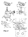
- Fig. 2 shows left and right each have a perspective view of the operating shaft 44 to be rotated with an operating knob 42.
- the actuating shaft 44 protrudes on the front panel 102 of the circuit breaker out of the housing part 110 of the circuit breaker.
- the housing part 110 has two connection surfaces 104 and 106, which are arranged parallel to one another. The surfaces are parallel to the axis of the actuating shaft 44 and perpendicular to the mounting plane and also perpendicular to the front panel 102.
- a linear guide member 116 is formed, which is shaped according to Figure 2 as a dovetail guide.
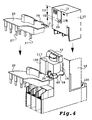
- the linear guide element 116 serves to guide the guide rail 16 formed on the tripping module 10 (compare FIGS. 3 and 4).
- a locking collar 48 is formed, which is not around the entire circumference - but about 150 ° of the circular sector - is present.
- the collar 48 has two sections 50 and 52 which differ by the radius R1 and R2.
- the first portion 52 has a larger radius R1 than the second portion 50 measured from the center of the axis of the actuating shaft 44th
- the collar portion 52 In the ON position of the circuit breaker and operating shaft 44, the collar portion 52 exits the wall 102 through an opening 118 (see FIG. 2, left) into the guide profile and fully engages the profile of the guide member 116 as shown in FIG lower part of Fig. 3 can be seen. After a left turn of the actuating shaft by 90 ° (again in the view of FIG. 3), the portion 52 is disengaged from the guide member 116; Only the second section 50 is located in the region of the profile of the guide element 116. This ensures that in the ON position of the switching mechanism, the collar is fully in the profile of the guide element and blocks the insertion of the additional module. When rotated by 90 ° - and thus rotation in the switch position OFF - the first section 52 releases the profile. In the OFF position of the circuit breaker and the actuating shaft 44, the first portion 52 of the collar 48 does not engage in the profile of the guide member 116. The rail can slide in the linear guide element 116, the additional module 10 can be inserted or pulled
- a rigid contact bridge (or referred to as connector block) may be provided as an additional module.
- the connector module 20 is approximately plate-shaped. On it are on both sides, projecting downwards and outstanding three pairs of plug contacts (27 ', 27 ") are present First plug contacts 27' engage in corresponding terminal bushes of the contactor - not shown in detail in the figure -, while second plug contacts 27" in corresponding Contact openings of the circuit breaker or another previously infected mechanical connector are inserted and come into conductive contact with the clamping bushes located there. The mentioned contact openings are not shown in detail in FIG. 4. Each contact pair 27'-27 "provides a power connection between the circuit breaker and the contactor.
- the procedure is such that first the circuit breaker is fixed on a base (for example on a mounting rail).
- Other devices e.g. the contactor and a mechanical connector are (also in applications with higher switching capacity) also mounted on the base (mounting rail) and connected to a contact bridge (20) with contacts of the circuit breaker.
- Contact bridges (20) in combination with the mechanical connector still have the special function of increasing the mechanical stability of the circuit-breaker / contactor combination.
- a contact bridge should only be inserted or pulled when the switch is off.
- the second associated locking function is provided on the collar there are two sections: a first section as a bar for the guide profile and a second section as an actuator edge (abutting edge) 53 for a locking element 60 mounted against the force of a spring.
- the blocking element 60 is shown in FIG. 2 on the left, in FIG and 4 drawn.
- the mode of action is such that, with a movement of the actuating shaft, the abutting edge 53 transmits the slider 60 in a straight line in a translatory manner an opening from the wall 104 is moved into the profile of the guide element 117.
- the movement of the actuating shaft is in the view of FIG. 3 to the right; this corresponds to the rotation in ON-switching direction.
- the extended in the locking situation collar enters the engagement slot 19 and blocks the movement of an additional module.
- the gap 19 is arranged so that it corresponds to the position of the collar in the inserted position of the additional module.
- a nose 18 is formed following the gap.
- the length (T2) and the position of the nose (T1 + T2 in Fig. 4) and their distance from the contact sockets in the circuit breaker are such that the plug contacts of an inserted to the stop of the nose to the collar additional module have not yet reached the contact sockets ,
Landscapes
- Breakers (AREA)
- Switch Cases, Indication, And Locking (AREA)
- Keying Circuit Devices (AREA)
- Lock And Its Accessories (AREA)
- Switches With Compound Operations (AREA)
Applications Claiming Priority (1)
| Application Number | Priority Date | Filing Date | Title |
|---|---|---|---|
| DE102006018852A DE102006018852B8 (de) | 2006-04-22 | 2006-04-22 | Handbetätigter Schutzschalter |
Publications (3)
| Publication Number | Publication Date |
|---|---|
| EP1848020A2 true EP1848020A2 (fr) | 2007-10-24 |
| EP1848020A3 EP1848020A3 (fr) | 2008-06-04 |
| EP1848020B1 EP1848020B1 (fr) | 2009-06-10 |
Family
ID=38091198
Family Applications (1)
| Application Number | Title | Priority Date | Filing Date |
|---|---|---|---|
| EP07007798A Not-in-force EP1848020B1 (fr) | 2006-04-22 | 2007-04-17 | Coupe-circuit actionné manuellement |
Country Status (5)
| Country | Link |
|---|---|
| EP (1) | EP1848020B1 (fr) |
| CN (1) | CN101060045B (fr) |
| AT (1) | ATE433601T1 (fr) |
| DE (2) | DE102006018852B8 (fr) |
| ES (1) | ES2326556T3 (fr) |
Cited By (2)
| Publication number | Priority date | Publication date | Assignee | Title |
|---|---|---|---|---|
| DE102011089591A1 (de) * | 2011-12-22 | 2013-06-27 | Siemens Aktiengesellschaft | Leistungsschalter und Adapter zum Koppeln eines Leistungsschalters mit einem Zusatzmodul |
| CN117275986A (zh) * | 2022-06-13 | 2023-12-22 | 上海良信电器股份有限公司 | 一种智能断路器控制器耐压检测隔离结构 |
Families Citing this family (11)
| Publication number | Priority date | Publication date | Assignee | Title |
|---|---|---|---|---|
| DE102008031335B4 (de) | 2008-07-02 | 2012-03-22 | Eaton Industries Gmbh | Elektrisches Schutzschaltgerät mit Steuerelektronik |
| DE102009023347A1 (de) * | 2009-05-29 | 2010-12-30 | Eaton Industries Gmbh | Handbetätigter Schutzschalter mit austauschbarem Auslösemodul |
| EP2549515A1 (fr) * | 2011-07-21 | 2013-01-23 | Eaton Industries GmbH | Agencement de commutation pour création et/ou séparation d'une connexion d'une fiche avec une contre-fiche |
| CN103187186B (zh) * | 2011-12-27 | 2016-04-27 | 苏州万龙电气集团股份有限公司 | 一种隔离开关装置 |
| CN103187190A (zh) * | 2011-12-27 | 2013-07-03 | 苏州万龙电气集团股份有限公司 | 一种隔离开关安全自锁装置 |
| DE102012106963A1 (de) * | 2012-07-31 | 2014-02-20 | Eaton Electrical Ip Gmbh & Co. Kg | Schaltgerätanordnung |
| EP2802070A1 (fr) * | 2013-05-07 | 2014-11-12 | Siemens Aktiengesellschaft | Démarreur de moteur doté d'une détection d'état pour le déverrouillage mécanique d'un module terminal |
| US20150014277A1 (en) * | 2013-07-15 | 2015-01-15 | Eaton Corporation | Interchangeable switching module and electrical switching apparatus including the same |
| CN104916510B (zh) * | 2015-05-20 | 2017-03-01 | 浙江天正电气股份有限公司 | 一种热继电器的复位装置 |
| DE102017211552A1 (de) * | 2017-07-06 | 2019-01-10 | Siemens Aktiengesellschaft | Elektronische Auslöseeinheit und Modul |
| CN118969571B (zh) * | 2024-10-18 | 2025-02-11 | 德力西电气有限公司 | 一种断路器 |
Family Cites Families (8)
| Publication number | Priority date | Publication date | Assignee | Title |
|---|---|---|---|---|
| CH319019A (de) * | 1954-05-12 | 1957-01-31 | Sprecher & Schuh Ag | Motorschutzschalter |
| FR2605150B1 (fr) * | 1986-10-09 | 1988-12-30 | Telemecanique Electrique | Appareil electro-magnetique de commutation ayant des interrupteurs interchangeables |
| DE3642719A1 (de) * | 1986-12-13 | 1988-06-16 | Kloeckner Moeller Elektrizit | Handbetaetigter schutzschalter |
| FR2638563B1 (fr) * | 1988-10-27 | 1990-12-14 | Telemecanique Electrique | Dispositif de securite pour appareil de commutation realise par l'assemblage de plusieurs elements modulaires amovibles |
| FR2685124B1 (fr) * | 1991-12-17 | 1994-03-18 | Telemecanique | Appareil interrupteur de protection tel que contacteur-disjoncteur. |
| FR2696042B1 (fr) * | 1992-09-24 | 1994-12-09 | Telemecanique | Appareil sectionneur associable à un disjoncteur. |
| US5634554A (en) * | 1994-12-15 | 1997-06-03 | Siemens Energy & Automation, Inc. | Interface connection for a circuit breaker plug-in trip unit |
| DE19515923C2 (de) * | 1995-05-02 | 1997-05-28 | Woehner Gmbh & Co Kg | Sammelschienen-Adapter |
-
2006
- 2006-04-22 DE DE102006018852A patent/DE102006018852B8/de not_active Expired - Fee Related
-
2007
- 2007-04-17 AT AT07007798T patent/ATE433601T1/de active
- 2007-04-17 DE DE502007000843T patent/DE502007000843D1/de active Active
- 2007-04-17 ES ES07007798T patent/ES2326556T3/es active Active
- 2007-04-17 EP EP07007798A patent/EP1848020B1/fr not_active Not-in-force
- 2007-04-20 CN CN2007101008689A patent/CN101060045B/zh not_active Expired - Fee Related
Cited By (3)
| Publication number | Priority date | Publication date | Assignee | Title |
|---|---|---|---|---|
| DE102011089591A1 (de) * | 2011-12-22 | 2013-06-27 | Siemens Aktiengesellschaft | Leistungsschalter und Adapter zum Koppeln eines Leistungsschalters mit einem Zusatzmodul |
| DE102011089591B4 (de) | 2011-12-22 | 2025-02-06 | Siemens Aktiengesellschaft | Adapter zum Koppeln eines Leistungsschalters mit einem Zusatzmodul |
| CN117275986A (zh) * | 2022-06-13 | 2023-12-22 | 上海良信电器股份有限公司 | 一种智能断路器控制器耐压检测隔离结构 |
Also Published As
| Publication number | Publication date |
|---|---|
| DE502007000843D1 (de) | 2009-07-23 |
| EP1848020B1 (fr) | 2009-06-10 |
| EP1848020A3 (fr) | 2008-06-04 |
| ATE433601T1 (de) | 2009-06-15 |
| DE102006018852B3 (de) | 2007-09-13 |
| CN101060045A (zh) | 2007-10-24 |
| DE102006018852B8 (de) | 2008-04-17 |
| ES2326556T3 (es) | 2009-10-14 |
| CN101060045B (zh) | 2011-08-10 |
Similar Documents
| Publication | Publication Date | Title |
|---|---|---|
| EP1848020B1 (fr) | Coupe-circuit actionné manuellement | |
| DE19937017C1 (de) | Mehrpolige Schaltersicherungsanordnung für Sammelschienensysteme | |
| DE102008031335B4 (de) | Elektrisches Schutzschaltgerät mit Steuerelektronik | |
| DE69904274T2 (de) | Schutzvorrichtung für elektrischen Anlagen gegen Speisungsstörungen | |
| EP2016605B1 (fr) | Disjoncteur pour la protection d'un moteur et/ou la protection de lignes | |
| EP0274624B1 (fr) | Disjoncteur a commande manuelle | |
| EP1198807A1 (fr) | Unite de fusible a commutateur pourvue d'un verrouillage de maintien | |
| EP2188819B1 (fr) | Interrupteur-sectionneur | |
| EP3016122B1 (fr) | Système de disjoncteur multipolaire pour jeux de barres collectrices | |
| EP2975708B1 (fr) | Systeme d'adaptateur dote d'un adaptateur pour rails collecteurs et module de raccordement d'adaptateur | |
| DE102004040288B4 (de) | Schutzschalter mit Kurzschluss- und Überlastauslöseanzeige sowie entsprechendes Verfahren | |
| EP3175471B1 (fr) | Dispositif de commutation | |
| DE102012203250B4 (de) | Einschubrahmen für ein elektrisches Einschubschaltgerät sowie Einheit aus einem Einschubrahmen und einem elektrischen Einschubschaltgerät | |
| EP2819246B1 (fr) | Dispositif de raccordement, notamment appareil de commutation, équipé d'une borne à ressort et d'un entraînement destiné à l'actionnement de la borne à ressort | |
| EP3673547B1 (fr) | Combinaison d'appareils servant à la protection de réseaux électriques contre des surtensions ou des surintensités | |
| EP1671342B1 (fr) | Disjoncteur | |
| DE102012203511A1 (de) | Einschubrahmen für ein elektrisches Einschubschaltgerät sowie Einheit aus Einschubrahmen und elektrischem Einschubschaltgerät | |
| DE19934542C1 (de) | Schaltersicherungseinheit mit Halterverriegelung | |
| EP2637270B1 (fr) | Cadre amovible pour un appareil de commutation électrique enfichable, notamment un disjoncteur enfichable | |
| DE102019116242A1 (de) | Gerätekombination zum Schutz von elektrischen Netzen vor Überspannungen oder Überströmen | |
| DE10345785B3 (de) | Berührungsgeschützter Sicherungsschalter | |
| EP1676288B1 (fr) | Dispositif d'installation | |
| DE19712346A1 (de) | Vorrichtung für die Blockierung der Drehung einer Welle eines elektrischen Antriebs für einen bewegten Kontakt eines Schaltgeräts | |
| WO2009033838A1 (fr) | Interrupteur-sectionneur | |
| DE9321529U1 (de) | Fernsteuerbarer Schutzschalter |
Legal Events
| Date | Code | Title | Description |
|---|---|---|---|
| PUAI | Public reference made under article 153(3) epc to a published international application that has entered the european phase |
Free format text: ORIGINAL CODE: 0009012 |
|
| AK | Designated contracting states |
Kind code of ref document: A2 Designated state(s): AT BE BG CH CY CZ DE DK EE ES FI FR GB GR HU IE IS IT LI LT LU LV MC MT NL PL PT RO SE SI SK TR |
|
| AX | Request for extension of the european patent |
Extension state: AL BA HR MK YU |
|
| PUAL | Search report despatched |
Free format text: ORIGINAL CODE: 0009013 |
|
| AK | Designated contracting states |
Kind code of ref document: A3 Designated state(s): AT BE BG CH CY CZ DE DK EE ES FI FR GB GR HU IE IS IT LI LT LU LV MC MT NL PL PT RO SE SI SK TR |
|
| AX | Request for extension of the european patent |
Extension state: AL BA HR MK RS |
|
| RIC1 | Information provided on ipc code assigned before grant |
Ipc: H01H 71/02 20060101ALI20080429BHEP Ipc: H01H 71/74 20060101AFI20070608BHEP Ipc: H01H 71/08 20060101ALN20080429BHEP Ipc: H01H 9/22 20060101ALI20080429BHEP Ipc: H01H 89/06 20060101ALN20080429BHEP Ipc: H01H 73/08 20060101ALN20080429BHEP |
|
| 17P | Request for examination filed |
Effective date: 20080711 |
|
| GRAP | Despatch of communication of intention to grant a patent |
Free format text: ORIGINAL CODE: EPIDOSNIGR1 |
|
| GRAS | Grant fee paid |
Free format text: ORIGINAL CODE: EPIDOSNIGR3 |
|
| AKX | Designation fees paid |
Designated state(s): AT BE BG CH CY CZ DE DK EE ES FI FR GB GR HU IE IS IT LI LT LU LV MC MT NL PL PT RO SE SI SK TR |
|
| GRAA | (expected) grant |
Free format text: ORIGINAL CODE: 0009210 |
|
| AK | Designated contracting states |
Kind code of ref document: B1 Designated state(s): AT BE BG CH CY CZ DE DK EE ES FI FR GB GR HU IE IS IT LI LT LU LV MC MT NL PL PT RO SE SI SK TR |
|
| REG | Reference to a national code |
Ref country code: GB Ref legal event code: FG4D Free format text: NOT ENGLISH |
|
| REG | Reference to a national code |
Ref country code: CH Ref legal event code: EP |
|
| REG | Reference to a national code |
Ref country code: IE Ref legal event code: FG4D Free format text: LANGUAGE OF EP DOCUMENT: GERMAN |
|
| REF | Corresponds to: |
Ref document number: 502007000843 Country of ref document: DE Date of ref document: 20090723 Kind code of ref document: P |
|
| REG | Reference to a national code |
Ref country code: SE Ref legal event code: TRGR |
|
| REG | Reference to a national code |
Ref country code: ES Ref legal event code: FG2A Ref document number: 2326556 Country of ref document: ES Kind code of ref document: T3 |
|
| PG25 | Lapsed in a contracting state [announced via postgrant information from national office to epo] |
Ref country code: LT Free format text: LAPSE BECAUSE OF FAILURE TO SUBMIT A TRANSLATION OF THE DESCRIPTION OR TO PAY THE FEE WITHIN THE PRESCRIBED TIME-LIMIT Effective date: 20090610 Ref country code: FI Free format text: LAPSE BECAUSE OF FAILURE TO SUBMIT A TRANSLATION OF THE DESCRIPTION OR TO PAY THE FEE WITHIN THE PRESCRIBED TIME-LIMIT Effective date: 20090610 |
|
| NLV1 | Nl: lapsed or annulled due to failure to fulfill the requirements of art. 29p and 29m of the patents act | ||
| PG25 | Lapsed in a contracting state [announced via postgrant information from national office to epo] |
Ref country code: NL Free format text: LAPSE BECAUSE OF FAILURE TO SUBMIT A TRANSLATION OF THE DESCRIPTION OR TO PAY THE FEE WITHIN THE PRESCRIBED TIME-LIMIT Effective date: 20090610 Ref country code: LV Free format text: LAPSE BECAUSE OF FAILURE TO SUBMIT A TRANSLATION OF THE DESCRIPTION OR TO PAY THE FEE WITHIN THE PRESCRIBED TIME-LIMIT Effective date: 20090610 Ref country code: SI Free format text: LAPSE BECAUSE OF FAILURE TO SUBMIT A TRANSLATION OF THE DESCRIPTION OR TO PAY THE FEE WITHIN THE PRESCRIBED TIME-LIMIT Effective date: 20090610 Ref country code: PL Free format text: LAPSE BECAUSE OF FAILURE TO SUBMIT A TRANSLATION OF THE DESCRIPTION OR TO PAY THE FEE WITHIN THE PRESCRIBED TIME-LIMIT Effective date: 20090610 |
|
| REG | Reference to a national code |
Ref country code: IE Ref legal event code: FD4D |
|
| PG25 | Lapsed in a contracting state [announced via postgrant information from national office to epo] |
Ref country code: EE Free format text: LAPSE BECAUSE OF FAILURE TO SUBMIT A TRANSLATION OF THE DESCRIPTION OR TO PAY THE FEE WITHIN THE PRESCRIBED TIME-LIMIT Effective date: 20090610 Ref country code: IE Free format text: LAPSE BECAUSE OF FAILURE TO SUBMIT A TRANSLATION OF THE DESCRIPTION OR TO PAY THE FEE WITHIN THE PRESCRIBED TIME-LIMIT Effective date: 20090610 Ref country code: CZ Free format text: LAPSE BECAUSE OF FAILURE TO SUBMIT A TRANSLATION OF THE DESCRIPTION OR TO PAY THE FEE WITHIN THE PRESCRIBED TIME-LIMIT Effective date: 20090610 Ref country code: IS Free format text: LAPSE BECAUSE OF FAILURE TO SUBMIT A TRANSLATION OF THE DESCRIPTION OR TO PAY THE FEE WITHIN THE PRESCRIBED TIME-LIMIT Effective date: 20091010 Ref country code: RO Free format text: LAPSE BECAUSE OF FAILURE TO SUBMIT A TRANSLATION OF THE DESCRIPTION OR TO PAY THE FEE WITHIN THE PRESCRIBED TIME-LIMIT Effective date: 20090610 |
|
| PG25 | Lapsed in a contracting state [announced via postgrant information from national office to epo] |
Ref country code: SK Free format text: LAPSE BECAUSE OF FAILURE TO SUBMIT A TRANSLATION OF THE DESCRIPTION OR TO PAY THE FEE WITHIN THE PRESCRIBED TIME-LIMIT Effective date: 20090610 |
|
| PG25 | Lapsed in a contracting state [announced via postgrant information from national office to epo] |
Ref country code: PT Free format text: LAPSE BECAUSE OF FAILURE TO SUBMIT A TRANSLATION OF THE DESCRIPTION OR TO PAY THE FEE WITHIN THE PRESCRIBED TIME-LIMIT Effective date: 20091010 Ref country code: BG Free format text: LAPSE BECAUSE OF FAILURE TO SUBMIT A TRANSLATION OF THE DESCRIPTION OR TO PAY THE FEE WITHIN THE PRESCRIBED TIME-LIMIT Effective date: 20090910 |
|
| PLBE | No opposition filed within time limit |
Free format text: ORIGINAL CODE: 0009261 |
|
| STAA | Information on the status of an ep patent application or granted ep patent |
Free format text: STATUS: NO OPPOSITION FILED WITHIN TIME LIMIT |
|
| PG25 | Lapsed in a contracting state [announced via postgrant information from national office to epo] |
Ref country code: DK Free format text: LAPSE BECAUSE OF FAILURE TO SUBMIT A TRANSLATION OF THE DESCRIPTION OR TO PAY THE FEE WITHIN THE PRESCRIBED TIME-LIMIT Effective date: 20090610 |
|
| RAP2 | Party data changed (patent owner data changed or rights of a patent transferred) |
Owner name: EATON INDUSTIES GMBH |
|
| 26N | No opposition filed |
Effective date: 20100311 |
|
| PG25 | Lapsed in a contracting state [announced via postgrant information from national office to epo] |
Ref country code: GR Free format text: LAPSE BECAUSE OF FAILURE TO SUBMIT A TRANSLATION OF THE DESCRIPTION OR TO PAY THE FEE WITHIN THE PRESCRIBED TIME-LIMIT Effective date: 20090911 |
|
| BERE | Be: lapsed |
Owner name: MOELLER G.M.B.H. Effective date: 20100430 |
|
| PG25 | Lapsed in a contracting state [announced via postgrant information from national office to epo] |
Ref country code: MC Free format text: LAPSE BECAUSE OF NON-PAYMENT OF DUE FEES Effective date: 20100430 |
|
| PG25 | Lapsed in a contracting state [announced via postgrant information from national office to epo] |
Ref country code: IT Free format text: LAPSE BECAUSE OF NON-PAYMENT OF DUE FEES Effective date: 20100417 Ref country code: BE Free format text: LAPSE BECAUSE OF NON-PAYMENT OF DUE FEES Effective date: 20100430 |
|
| PG25 | Lapsed in a contracting state [announced via postgrant information from national office to epo] |
Ref country code: MT Free format text: LAPSE BECAUSE OF FAILURE TO SUBMIT A TRANSLATION OF THE DESCRIPTION OR TO PAY THE FEE WITHIN THE PRESCRIBED TIME-LIMIT Effective date: 20090610 |
|
| REG | Reference to a national code |
Ref country code: CH Ref legal event code: PL |
|
| GBPC | Gb: european patent ceased through non-payment of renewal fee |
Effective date: 20110417 |
|
| PG25 | Lapsed in a contracting state [announced via postgrant information from national office to epo] |
Ref country code: CH Free format text: LAPSE BECAUSE OF NON-PAYMENT OF DUE FEES Effective date: 20110430 Ref country code: LI Free format text: LAPSE BECAUSE OF NON-PAYMENT OF DUE FEES Effective date: 20110430 |
|
| PG25 | Lapsed in a contracting state [announced via postgrant information from national office to epo] |
Ref country code: GB Free format text: LAPSE BECAUSE OF NON-PAYMENT OF DUE FEES Effective date: 20110417 |
|
| PG25 | Lapsed in a contracting state [announced via postgrant information from national office to epo] |
Ref country code: CY Free format text: LAPSE BECAUSE OF FAILURE TO SUBMIT A TRANSLATION OF THE DESCRIPTION OR TO PAY THE FEE WITHIN THE PRESCRIBED TIME-LIMIT Effective date: 20090610 |
|
| PG25 | Lapsed in a contracting state [announced via postgrant information from national office to epo] |
Ref country code: HU Free format text: LAPSE BECAUSE OF FAILURE TO SUBMIT A TRANSLATION OF THE DESCRIPTION OR TO PAY THE FEE WITHIN THE PRESCRIBED TIME-LIMIT Effective date: 20091211 Ref country code: LU Free format text: LAPSE BECAUSE OF NON-PAYMENT OF DUE FEES Effective date: 20100417 |
|
| PG25 | Lapsed in a contracting state [announced via postgrant information from national office to epo] |
Ref country code: TR Free format text: LAPSE BECAUSE OF FAILURE TO SUBMIT A TRANSLATION OF THE DESCRIPTION OR TO PAY THE FEE WITHIN THE PRESCRIBED TIME-LIMIT Effective date: 20090610 |
|
| PGFP | Annual fee paid to national office [announced via postgrant information from national office to epo] |
Ref country code: ES Payment date: 20120423 Year of fee payment: 6 |
|
| REG | Reference to a national code |
Ref country code: AT Ref legal event code: MM01 Ref document number: 433601 Country of ref document: AT Kind code of ref document: T Effective date: 20120417 |
|
| PG25 | Lapsed in a contracting state [announced via postgrant information from national office to epo] |
Ref country code: AT Free format text: LAPSE BECAUSE OF NON-PAYMENT OF DUE FEES Effective date: 20120417 |
|
| PGFP | Annual fee paid to national office [announced via postgrant information from national office to epo] |
Ref country code: DE Payment date: 20130430 Year of fee payment: 7 Ref country code: SE Payment date: 20130405 Year of fee payment: 7 |
|
| PGFP | Annual fee paid to national office [announced via postgrant information from national office to epo] |
Ref country code: IT Payment date: 20130416 Year of fee payment: 7 Ref country code: FR Payment date: 20130417 Year of fee payment: 7 |
|
| REG | Reference to a national code |
Ref country code: DE Ref legal event code: R119 Ref document number: 502007000843 Country of ref document: DE |
|
| REG | Reference to a national code |
Ref country code: SE Ref legal event code: EUG |
|
| REG | Reference to a national code |
Ref country code: DE Ref legal event code: R119 Ref document number: 502007000843 Country of ref document: DE Effective date: 20141101 |
|
| REG | Reference to a national code |
Ref country code: FR Ref legal event code: ST Effective date: 20141231 |
|
| PG25 | Lapsed in a contracting state [announced via postgrant information from national office to epo] |
Ref country code: SE Free format text: LAPSE BECAUSE OF NON-PAYMENT OF DUE FEES Effective date: 20140418 Ref country code: DE Free format text: LAPSE BECAUSE OF NON-PAYMENT OF DUE FEES Effective date: 20141101 |
|
| PG25 | Lapsed in a contracting state [announced via postgrant information from national office to epo] |
Ref country code: FR Free format text: LAPSE BECAUSE OF NON-PAYMENT OF DUE FEES Effective date: 20140430 |
|
| PG25 | Lapsed in a contracting state [announced via postgrant information from national office to epo] |
Ref country code: IT Free format text: LAPSE BECAUSE OF NON-PAYMENT OF DUE FEES Effective date: 20140417 |
|
| PG25 | Lapsed in a contracting state [announced via postgrant information from national office to epo] |
Ref country code: ES Free format text: LAPSE BECAUSE OF NON-PAYMENT OF DUE FEES Effective date: 20140418 |