EP1848030A2 - Procédé de fabrication d'un dispositif semi-conducteur - Google Patents
Procédé de fabrication d'un dispositif semi-conducteur Download PDFInfo
- Publication number
- EP1848030A2 EP1848030A2 EP07007105A EP07007105A EP1848030A2 EP 1848030 A2 EP1848030 A2 EP 1848030A2 EP 07007105 A EP07007105 A EP 07007105A EP 07007105 A EP07007105 A EP 07007105A EP 1848030 A2 EP1848030 A2 EP 1848030A2
- Authority
- EP
- European Patent Office
- Prior art keywords
- conductive bump
- semiconductor device
- manufacturing
- semiconductor apparatus
- external wire
- Prior art date
- Legal status (The legal status is an assumption and is not a legal conclusion. Google has not performed a legal analysis and makes no representation as to the accuracy of the status listed.)
- Withdrawn
Links
Images




Classifications
-
- H—ELECTRICITY
- H10—SEMICONDUCTOR DEVICES; ELECTRIC SOLID-STATE DEVICES NOT OTHERWISE PROVIDED FOR
- H10W—GENERIC PACKAGES, INTERCONNECTIONS, CONNECTORS OR OTHER CONSTRUCTIONAL DETAILS OF DEVICES COVERED BY CLASS H10
- H10W70/00—Package substrates; Interposers; Redistribution layers [RDL]
- H10W70/40—Leadframes
- H10W70/464—Additional interconnections in combination with leadframes
- H10W70/466—Tape carriers or flat leads
-
- H—ELECTRICITY
- H10—SEMICONDUCTOR DEVICES; ELECTRIC SOLID-STATE DEVICES NOT OTHERWISE PROVIDED FOR
- H10W—GENERIC PACKAGES, INTERCONNECTIONS, CONNECTORS OR OTHER CONSTRUCTIONAL DETAILS OF DEVICES COVERED BY CLASS H10
- H10W70/00—Package substrates; Interposers; Redistribution layers [RDL]
- H10W70/40—Leadframes
- H10W70/481—Leadframes for devices being provided for in groups H10D8/00 - H10D48/00
-
- H—ELECTRICITY
- H10—SEMICONDUCTOR DEVICES; ELECTRIC SOLID-STATE DEVICES NOT OTHERWISE PROVIDED FOR
- H10W—GENERIC PACKAGES, INTERCONNECTIONS, CONNECTORS OR OTHER CONSTRUCTIONAL DETAILS OF DEVICES COVERED BY CLASS H10
- H10W99/00—Subject matter not provided for in other groups of this subclass
-
- H—ELECTRICITY
- H10—SEMICONDUCTOR DEVICES; ELECTRIC SOLID-STATE DEVICES NOT OTHERWISE PROVIDED FOR
- H10W—GENERIC PACKAGES, INTERCONNECTIONS, CONNECTORS OR OTHER CONSTRUCTIONAL DETAILS OF DEVICES COVERED BY CLASS H10
- H10W72/00—Interconnections or connectors in packages
- H10W72/071—Connecting or disconnecting
- H10W72/072—Connecting or disconnecting of bump connectors
- H10W72/07231—Techniques
- H10W72/07235—Applying EM radiation, e.g. induction heating or using a laser
-
- H—ELECTRICITY
- H10—SEMICONDUCTOR DEVICES; ELECTRIC SOLID-STATE DEVICES NOT OTHERWISE PROVIDED FOR
- H10W—GENERIC PACKAGES, INTERCONNECTIONS, CONNECTORS OR OTHER CONSTRUCTIONAL DETAILS OF DEVICES COVERED BY CLASS H10
- H10W72/00—Interconnections or connectors in packages
- H10W72/071—Connecting or disconnecting
- H10W72/073—Connecting or disconnecting of die-attach connectors
- H10W72/07331—Connecting techniques
- H10W72/07336—Soldering or alloying
-
- H—ELECTRICITY
- H10—SEMICONDUCTOR DEVICES; ELECTRIC SOLID-STATE DEVICES NOT OTHERWISE PROVIDED FOR
- H10W—GENERIC PACKAGES, INTERCONNECTIONS, CONNECTORS OR OTHER CONSTRUCTIONAL DETAILS OF DEVICES COVERED BY CLASS H10
- H10W72/00—Interconnections or connectors in packages
- H10W72/071—Connecting or disconnecting
- H10W72/073—Connecting or disconnecting of die-attach connectors
- H10W72/07331—Connecting techniques
- H10W72/07337—Connecting techniques using a polymer adhesive, e.g. an adhesive based on silicone or epoxy
-
- H—ELECTRICITY
- H10—SEMICONDUCTOR DEVICES; ELECTRIC SOLID-STATE DEVICES NOT OTHERWISE PROVIDED FOR
- H10W—GENERIC PACKAGES, INTERCONNECTIONS, CONNECTORS OR OTHER CONSTRUCTIONAL DETAILS OF DEVICES COVERED BY CLASS H10
- H10W72/00—Interconnections or connectors in packages
- H10W72/071—Connecting or disconnecting
- H10W72/076—Connecting or disconnecting of strap connectors
- H10W72/07631—Techniques
- H10W72/07635—Applying EM radiation, e.g. induction heating or using a laser
-
- H—ELECTRICITY
- H10—SEMICONDUCTOR DEVICES; ELECTRIC SOLID-STATE DEVICES NOT OTHERWISE PROVIDED FOR
- H10W—GENERIC PACKAGES, INTERCONNECTIONS, CONNECTORS OR OTHER CONSTRUCTIONAL DETAILS OF DEVICES COVERED BY CLASS H10
- H10W72/00—Interconnections or connectors in packages
- H10W72/071—Connecting or disconnecting
- H10W72/076—Connecting or disconnecting of strap connectors
- H10W72/07631—Techniques
- H10W72/07636—Soldering or alloying
-
- H—ELECTRICITY
- H10—SEMICONDUCTOR DEVICES; ELECTRIC SOLID-STATE DEVICES NOT OTHERWISE PROVIDED FOR
- H10W—GENERIC PACKAGES, INTERCONNECTIONS, CONNECTORS OR OTHER CONSTRUCTIONAL DETAILS OF DEVICES COVERED BY CLASS H10
- H10W72/00—Interconnections or connectors in packages
- H10W72/071—Connecting or disconnecting
- H10W72/076—Connecting or disconnecting of strap connectors
- H10W72/07651—Connecting or disconnecting of strap connectors characterised by changes in properties of the strap connectors during connecting
- H10W72/07653—Connecting or disconnecting of strap connectors characterised by changes in properties of the strap connectors during connecting changes in shapes
-
- H—ELECTRICITY
- H10—SEMICONDUCTOR DEVICES; ELECTRIC SOLID-STATE DEVICES NOT OTHERWISE PROVIDED FOR
- H10W—GENERIC PACKAGES, INTERCONNECTIONS, CONNECTORS OR OTHER CONSTRUCTIONAL DETAILS OF DEVICES COVERED BY CLASS H10
- H10W72/00—Interconnections or connectors in packages
- H10W72/50—Bond wires
- H10W72/531—Shapes of wire connectors
- H10W72/533—Cross-sectional shape
- H10W72/534—Cross-sectional shape being rectangular
-
- H—ELECTRICITY
- H10—SEMICONDUCTOR DEVICES; ELECTRIC SOLID-STATE DEVICES NOT OTHERWISE PROVIDED FOR
- H10W—GENERIC PACKAGES, INTERCONNECTIONS, CONNECTORS OR OTHER CONSTRUCTIONAL DETAILS OF DEVICES COVERED BY CLASS H10
- H10W72/00—Interconnections or connectors in packages
- H10W72/50—Bond wires
- H10W72/531—Shapes of wire connectors
- H10W72/536—Shapes of wire connectors the connected ends being ball-shaped
-
- H—ELECTRICITY
- H10—SEMICONDUCTOR DEVICES; ELECTRIC SOLID-STATE DEVICES NOT OTHERWISE PROVIDED FOR
- H10W—GENERIC PACKAGES, INTERCONNECTIONS, CONNECTORS OR OTHER CONSTRUCTIONAL DETAILS OF DEVICES COVERED BY CLASS H10
- H10W72/00—Interconnections or connectors in packages
- H10W72/50—Bond wires
- H10W72/551—Materials of bond wires
- H10W72/552—Materials of bond wires comprising metals or metalloids, e.g. silver
-
- H—ELECTRICITY
- H10—SEMICONDUCTOR DEVICES; ELECTRIC SOLID-STATE DEVICES NOT OTHERWISE PROVIDED FOR
- H10W—GENERIC PACKAGES, INTERCONNECTIONS, CONNECTORS OR OTHER CONSTRUCTIONAL DETAILS OF DEVICES COVERED BY CLASS H10
- H10W72/00—Interconnections or connectors in packages
- H10W72/50—Bond wires
- H10W72/551—Materials of bond wires
- H10W72/552—Materials of bond wires comprising metals or metalloids, e.g. silver
- H10W72/5522—Materials of bond wires comprising metals or metalloids, e.g. silver comprising gold [Au]
-
- H—ELECTRICITY
- H10—SEMICONDUCTOR DEVICES; ELECTRIC SOLID-STATE DEVICES NOT OTHERWISE PROVIDED FOR
- H10W—GENERIC PACKAGES, INTERCONNECTIONS, CONNECTORS OR OTHER CONSTRUCTIONAL DETAILS OF DEVICES COVERED BY CLASS H10
- H10W72/00—Interconnections or connectors in packages
- H10W72/50—Bond wires
- H10W72/551—Materials of bond wires
- H10W72/552—Materials of bond wires comprising metals or metalloids, e.g. silver
- H10W72/5524—Materials of bond wires comprising metals or metalloids, e.g. silver comprising aluminium [Al]
-
- H—ELECTRICITY
- H10—SEMICONDUCTOR DEVICES; ELECTRIC SOLID-STATE DEVICES NOT OTHERWISE PROVIDED FOR
- H10W—GENERIC PACKAGES, INTERCONNECTIONS, CONNECTORS OR OTHER CONSTRUCTIONAL DETAILS OF DEVICES COVERED BY CLASS H10
- H10W72/00—Interconnections or connectors in packages
- H10W72/50—Bond wires
- H10W72/551—Materials of bond wires
- H10W72/552—Materials of bond wires comprising metals or metalloids, e.g. silver
- H10W72/5525—Materials of bond wires comprising metals or metalloids, e.g. silver comprising copper [Cu]
-
- H—ELECTRICITY
- H10—SEMICONDUCTOR DEVICES; ELECTRIC SOLID-STATE DEVICES NOT OTHERWISE PROVIDED FOR
- H10W—GENERIC PACKAGES, INTERCONNECTIONS, CONNECTORS OR OTHER CONSTRUCTIONAL DETAILS OF DEVICES COVERED BY CLASS H10
- H10W72/00—Interconnections or connectors in packages
- H10W72/60—Strap connectors, e.g. thick copper clips for grounding of power devices
- H10W72/651—Materials of strap connectors
- H10W72/652—Materials of strap connectors comprising metals or metalloids, e.g. silver
-
- H—ELECTRICITY
- H10—SEMICONDUCTOR DEVICES; ELECTRIC SOLID-STATE DEVICES NOT OTHERWISE PROVIDED FOR
- H10W—GENERIC PACKAGES, INTERCONNECTIONS, CONNECTORS OR OTHER CONSTRUCTIONAL DETAILS OF DEVICES COVERED BY CLASS H10
- H10W72/00—Interconnections or connectors in packages
- H10W72/851—Dispositions of multiple connectors or interconnections
- H10W72/853—On the same surface
- H10W72/871—Bond wires and strap connectors
-
- H—ELECTRICITY
- H10—SEMICONDUCTOR DEVICES; ELECTRIC SOLID-STATE DEVICES NOT OTHERWISE PROVIDED FOR
- H10W—GENERIC PACKAGES, INTERCONNECTIONS, CONNECTORS OR OTHER CONSTRUCTIONAL DETAILS OF DEVICES COVERED BY CLASS H10
- H10W72/00—Interconnections or connectors in packages
- H10W72/90—Bond pads, in general
-
- H—ELECTRICITY
- H10—SEMICONDUCTOR DEVICES; ELECTRIC SOLID-STATE DEVICES NOT OTHERWISE PROVIDED FOR
- H10W—GENERIC PACKAGES, INTERCONNECTIONS, CONNECTORS OR OTHER CONSTRUCTIONAL DETAILS OF DEVICES COVERED BY CLASS H10
- H10W72/00—Interconnections or connectors in packages
- H10W72/90—Bond pads, in general
- H10W72/921—Structures or relative sizes of bond pads
- H10W72/926—Multiple bond pads having different sizes
-
- H—ELECTRICITY
- H10—SEMICONDUCTOR DEVICES; ELECTRIC SOLID-STATE DEVICES NOT OTHERWISE PROVIDED FOR
- H10W—GENERIC PACKAGES, INTERCONNECTIONS, CONNECTORS OR OTHER CONSTRUCTIONAL DETAILS OF DEVICES COVERED BY CLASS H10
- H10W72/00—Interconnections or connectors in packages
- H10W72/90—Bond pads, in general
- H10W72/941—Dispositions of bond pads
- H10W72/9415—Dispositions of bond pads relative to the surface, e.g. recessed, protruding
-
- H—ELECTRICITY
- H10—SEMICONDUCTOR DEVICES; ELECTRIC SOLID-STATE DEVICES NOT OTHERWISE PROVIDED FOR
- H10W—GENERIC PACKAGES, INTERCONNECTIONS, CONNECTORS OR OTHER CONSTRUCTIONAL DETAILS OF DEVICES COVERED BY CLASS H10
- H10W72/00—Interconnections or connectors in packages
- H10W72/90—Bond pads, in general
- H10W72/951—Materials of bond pads
- H10W72/952—Materials of bond pads comprising metals or metalloids, e.g. PbSn, Ag or Cu
-
- H—ELECTRICITY
- H10—SEMICONDUCTOR DEVICES; ELECTRIC SOLID-STATE DEVICES NOT OTHERWISE PROVIDED FOR
- H10W—GENERIC PACKAGES, INTERCONNECTIONS, CONNECTORS OR OTHER CONSTRUCTIONAL DETAILS OF DEVICES COVERED BY CLASS H10
- H10W74/00—Encapsulations, e.g. protective coatings
-
- H—ELECTRICITY
- H10—SEMICONDUCTOR DEVICES; ELECTRIC SOLID-STATE DEVICES NOT OTHERWISE PROVIDED FOR
- H10W—GENERIC PACKAGES, INTERCONNECTIONS, CONNECTORS OR OTHER CONSTRUCTIONAL DETAILS OF DEVICES COVERED BY CLASS H10
- H10W90/00—Package configurations
- H10W90/701—Package configurations characterised by the relative positions of pads or connectors relative to package parts
- H10W90/721—Package configurations characterised by the relative positions of pads or connectors relative to package parts of bump connectors
- H10W90/726—Package configurations characterised by the relative positions of pads or connectors relative to package parts of bump connectors between a chip and a stacked lead frame, conducting package substrate or heat sink
-
- H—ELECTRICITY
- H10—SEMICONDUCTOR DEVICES; ELECTRIC SOLID-STATE DEVICES NOT OTHERWISE PROVIDED FOR
- H10W—GENERIC PACKAGES, INTERCONNECTIONS, CONNECTORS OR OTHER CONSTRUCTIONAL DETAILS OF DEVICES COVERED BY CLASS H10
- H10W90/00—Package configurations
- H10W90/701—Package configurations characterised by the relative positions of pads or connectors relative to package parts
- H10W90/751—Package configurations characterised by the relative positions of pads or connectors relative to package parts of bond wires
- H10W90/756—Package configurations characterised by the relative positions of pads or connectors relative to package parts of bond wires between a chip and a stacked lead frame, conducting package substrate or heat sink
-
- H—ELECTRICITY
- H10—SEMICONDUCTOR DEVICES; ELECTRIC SOLID-STATE DEVICES NOT OTHERWISE PROVIDED FOR
- H10W—GENERIC PACKAGES, INTERCONNECTIONS, CONNECTORS OR OTHER CONSTRUCTIONAL DETAILS OF DEVICES COVERED BY CLASS H10
- H10W90/00—Package configurations
- H10W90/701—Package configurations characterised by the relative positions of pads or connectors relative to package parts
- H10W90/761—Package configurations characterised by the relative positions of pads or connectors relative to package parts of strap connectors
- H10W90/766—Package configurations characterised by the relative positions of pads or connectors relative to package parts of strap connectors between a chip and a stacked lead frame, conducting package substrate or heat sink
Definitions
- the present invention relates to a method of manufacturing a semiconductor apparatus and, particularly, to a method of manufacturing a semiconductor apparatus for large-current or low-resistance use.
- MOSFETs Metal-Oxide-Semiconductor Field-Effect Transistors
- a high current of about 1 to 200 A It thus requires a thick external wire with a large cross sectional area. Therefore, in order to draw a high current, a plurality of large-gauge bonding wires of about 100 to 500 ⁇ m have been connected as an external wire to a source electrode of a MOSFET.
- the bonding wires are connected to the source electrode typically by ultrasonic bonding or thermocompression bonding, and it requires a bonding area of about 1.5 to 3 times the wire cross-sectional area.
- the area of the source electrode or the gate electrode is limited to small and there is thus a limit to enlarge the wire cross-sectional area.
- a larger wire cross-sectional area requires higher pressure application to obtain a larger bonding strength, and the mechanical impact causes damage to a semiconductor device.
- the looping of large-gauge bonding wires leads to a decrease in productivity.
- a semiconductor apparatus and a manufacturing method of the same as described in Japanese Unexamined Patent Application Publication Nos. 2002-313851 (Oono et al. ) and 2002-314018 (Funato et al. ) use a flat-plate electric path member, instead of a bonding wire, as an external wire to thereby enlarge the cross-sectional area of the external wire.
- Figs. 6A and 6B are a horizontal cross-sectional view and a vertical cross-sectional view, respectively, of a semiconductor device (Small Out-line Package (SOP) - 8 packages) taught by Oono.
- SOP Small Out-line Package
- a semiconductor device 105 is included in a molding resin 102.
- a source electrode 104s and a gate electrode 104g are formed on the top surface, and a drain electrode (not shown) is formed on the under surface.
- drain-side terminals 103b out of eight leads are integrated into one set to form a drain-side post 107d inside the molding resin 102.
- the semiconductor device 105 is placed above the drain-side post 107d, such that the drain-side post 107d is electrically connected with the drain electrode (not shown).
- three source-side terminals 103s are integrated into one set to form a source-side post 107s inside the molding resin 102, and one gate-side terminal 103g forms a gate-side post 107g inside the molding resin 102.
- the source-side post 107s and the source electrode 104s are electrically connected by an electric path member 106.
- An electrode-side connecting portion 106a formed at one end of the electric path member 106 and the source electrode 104s, and a lead-side connecting portion 106b formed at the other end of the electric path member 106 and the source-side post 107s, respectively, are connected by ultrasonic bonding in direct contact with each other.
- the use of the flat-plate electric path member 106 allows the cross sectional area of the current path flowing between the source-side post 107s and the source electrode 104s to be significantly larger than that of the current path flowing through a plurality of bonding wires.
- the gate-side post 107g is electrically connected with the gate electrode 104g by one boding wire 108.
- FIG. 7 is a cross-sectional view showing a semiconductor apparatus according to Japanese Unexamined Patent Application Publication No. 61-53737 (Fig. 2) (Matsuda et al.).
- a semiconductor device 201 is placed on a die pad 203 of a lead frame.
- An electrode pad 202 placed on the semiconductor device 201 and a lead 204 of the lead frame are electrically connected by a bonding wire 205.
- the wire 205 and the electrode pad 202 are connected by laser welding.
- the ultrasonic bonding process taught by Oono et al. and Funato et al. can cause mechanical damage to the semiconductor device due to ultrasonic vibration. Further, because it is a mechanical bonding process, the bonding can be difficult for some metals.
- a step of mounting a semiconductor device on a die pad (island) of a lead frame is carried out at the temperature of 300 °C or higher; as a result, an oxide film is formed on the surface of the electrode of the semiconductor device.
- ultrasonic vibration is applied to the external wire and the electrode that are arranged in contact with each other.
- the external wire has a large cross-sectional area, the mechanical impact to be applied to the electrode due to the vibration of the external wire becomes large, which can cause the mechanical damage to reach the semiconductor device under the electrode.
- a MOSFET has an active cell immediately under the electrode and a product can be breakdown. Further, the bonding is difficult for Cu or the like with a thick surface oxide film.
- the laser bonding process taught by Matsuda et al. can cause thermal damage to the semiconductor device under the electrode.
- large-gauge wires of about 100 to 500 ⁇ m or above are used to reduce the resistance in order for the MOSFET to carry a high current. This corresponds to the thickness of 100 to 500 ⁇ m.
- the thickness of the electrode is as small as about 2 to 6 ⁇ m as described in Oono et al.
- the adjustment of laser intensity is extremely difficult when laser-welding the members having significantly different thicknesses because high laser intensity leads to thermal damage to the semiconductor device by laser, and low laser intensity fails to establish connection or obtain desired connection intensity.
- a method of manufacturing a semiconductor apparatus including forming an electrode on a semiconductor device, forming a conductive bump on the electrode, placing an external wire on the conductive bump, and laser-welding the external wire and the conductive bump to establish electrical connection.
- the present invention provides a method of manufacturing a semiconductor apparatus capable of preventing mechanical and thermal damage to a semiconductor device and providing high reliability and productivity.
- a first embodiment of the present invention is described hereinbelow in detail with reference to the drawings.
- the present invention is applied to a semiconductor apparatus for high-current or low-resistance use in which a number of MOSFETs are combined into one MOSFET. While a single transistor normally carries a current of about 0.1A, such a transistor can carry a current of about 1 to 200A and can be used for power supply in consumer-electronics products, driving of vehicle motors, or the like.
- Fig. 1A is a perspective view of a semiconductor apparatus according to the first embodiment of the present invention.
- Fig. 1B is a cross-sectional view along line X-X in Fig. 1A.
- the semiconductor apparatus includes a die pad (island) 1 of a lead frame, a semiconductor device (die) 2, an electrode pad 3, a conductive bump 4, and a lead 5 of a lead frame.
- these elements are covered with a molding resin made of an epoxy resin or the like and packaged entirely except for one end (external lead) of the lead 5.
- the die pad 1 is a part of a lead frame.
- the lead frame is made of a metal that mainly contains Au, Cu, Ni, Ag, Al, or Pd.
- a metal material may be formed on the surface of the die pad 1.
- the die pad 1 may be plated with Ni, Ag or the like as needed.
- the semiconductor device (die) 2 which may be a vertical MOSFET, is placed on the die pad 1.
- a drain electrode (not shown) is placed on the under surface of the semiconductor device 2 and connected with the die pad 1.
- the electrode pad 3 is placed on the semiconductor device 3 and includes a source electrode 3a and a gate electrode 3b as shown in Fig. 1A.
- the electrode pad 3 may be a metal film with the thickness of about 5 ⁇ m which mainly contains Au, Cu, Ni, Ag, Al, or Pd.
- the conductive bump 4 is placed on the electrode pad 3 and electrically connected therewith.
- the conductive bump 4 is made of Au, Cu, Ni, Ag, Al or Pd, or an alloy mainly containing those. The use of various kinds of solder is also possible.
- the height of the conductive bump 4 is appropriately set according to the thickness of a connecting portion 5a.
- the thickness of the connecting portion 5a is set to 1 to 30 times the height of the conductive bump 4 so as to prevent thermal damage to the semiconductor device 2 due to laser welding and to obtain suitable connection intensity. Being more than 30 times causes the adjustment of laser intensity to be extremely difficult. If the laser intensity is too high, laser reaches the electrode pad 3, or even the semiconductor device 2, under the conductive bump 4 to cause thermal damage thereto. If, on the other hand, the laser intensity is too low, it fails to establish connection or obtain desired connection intensity. Being less than 1 time does not cause any problem to laser welding; however, if the thickness of the connecting portion 5a is too small, resistance increases to cause the degradation of electrical characteristics for high-current or low-resistance use.
- the height of the conductive bump 4 is set to about 5 ⁇ m or larger to prevent thermal damage from being given to the semiconductor device 2 due to laser welding.
- the thickness of the connecting portion 5a should be at least 5 ⁇ m, though it depends on the cross sectional area and resistance. If the height of the conductive bump 4 is larger, the thickness of the connecting portion 5a may be less than 1 time the height of the conductive bump 4. However, the resistance is low when it is less than 1 time. More preferably, the thickness of the connecting portion 5a is 1 to 10 times the height of the conductive bump 4.
- the lead 5 is a part of a lead frame that may be the same as or different from the die pad 1, and it corresponds to an external wire according to the present invention.
- One end (internal lead) of the lead 5 is placed on the conductive bump 4.
- the internal lead according to the first embodiment has the flat-plate connecting portion 5a.
- the connecting portion 5a and the conductive bump 4 are laser-welded and electrically connected with each other.
- the contact area between the connecting portion 5a and the conductive bump 4 may be designed in light of desired current and resistance values.
- the lead 5 and the conductive bump 4 are connected directly without through a separate wire or the like. This eliminates an additional connecting portion to thereby provide a more reliable semiconductor apparatus.
- the other end (external lead) of the lead 5 is exposed outside the package and typically soldered onto a printed circuit board.
- the other end of the lead 5 may be laser-welded with a conductive bump that is placed on an electrode pad of another semiconductor device, so that two semiconductor devices are connected through the lead 5.
- the area of the connecting portion 5a may be larger than the area of the electrode pad 3 but should be smaller than the semiconductor device 2. This is because the positioning for the laser welding is performed by recognizing the semiconductor device 2. This facilitates the positioning.
- a gate electrode is placed below the source electrode with an insulating film interposed therebetween.
- the insulating film may be formed of BPSG (boron phosphorous silicate glass), PSG (phosphorous silicate glass) or the like which are oxide silicon glass added with phosphorous or boron. If damage is given to the insulating film by laser welding, the MOSFET becomes inoperable.
- the insulating film is thus preferably formed of a heat resistant material.
- a method of manufacturing a semiconductor apparatus according to the first embodiment of the invention is described hereinafter.
- a lead frame having the flat-plate connecting portion 5a at an end of the lead 5 is prepared.
- the lead frame may be formed by patterning a thin-plate metal material by stamping, etching or the like.
- the connecting portion 5a is formed at an end of the lead 5 of the lead frame such that it has a given thickness in accordance with the size and shape of the source electrode 3a and the gate electrode 3b on the semiconductor device 2.
- the connecting portion 5a may be plated with Ni, Ag or the like as needed.
- Cu and Cu alloy are highly conductive and thus suitable as a lead frame material but less absorbent to laser.
- the use of Cu-Ni alloy is also possible.
- each semiconductor device 2 that is diced out from a semiconductor wafer is placed on the die pad 1, and the conductive bump 4 is formed on the electrode pad 3 by ultrasonic bonding. Specifically, an end of a wire-like material for the conductive bump 4 is heated and melted to form a ball, ultrasonic bonded, and then cut, thereby creating the conductive bump 4.
- the size of each conductive bump 4 may be about 30 to 200 ⁇ m in diameter and about 25 to 90 ⁇ m in height, which are smaller than the connecting portion 5a and the flat-plate current path member according to Oono et al. and Funato et al., so that the ultrasonic bonding of this step does not give any mechanical damage to the semiconductor device 2.
- the die pad 1 and the semiconductor device 2 may be electrically connected by solder, silver paste or the like.
- a method of creating the conductive bump 4 is not limited to the above-described ultrasonic bonding.
- the conductive bump 4 may be created by electrolytic plating or electroless plating on a semiconductor wafer. It is easy to form the conductive bump 4 with the thickness of about 5 to 20 ⁇ m.
- the conductive bump 4 is not limited to ball-shaped and it may be column or plug shaped. This method enables the creation of the conductive bumps 4 at a time on each semiconductor device and also enables the reduction of mechanical damage due to ultrasonic bonding.
- the size of the conductive bump 4 may be enlarged to 100 ⁇ m or above, which increases the laser welding area to thereby further reduce the resistance.
- the conductive bump 4 formed on the source electrode 3a and the gate electrode 3b is overlapped with the connecting portion 5a of the lead 5.
- the lead 5 may be a lead of a different lead frame from the die pad 1.
- the positioning of the semiconductor device 2 for laser welding can be performed at the accuracy of about 100 ⁇ m, which is easy.
- the semiconductor device is normally covered with a protective film which has an opening to expose the electrode of the semiconductor device.
- the external wire is laid out by mechanical handling, and the positioning accuracy is about ⁇ 25 ⁇ m at present.
- the conductive bumps 4 are sandwiched between the bonding portion 5a of the lead 5 and the protective film so as to avoid contact between the bonding portion 5a and the protective film. Therefore, it is possible to deviate from an opening to expose the electrode of the semiconductor device, and the displacement of about ⁇ 100 ⁇ m is allowable.
- a galvanometer for the laser welding enables one-time connection to enhance the productivity. Even if a slight gap exists between the connecting portion 5a and the conductive bump 4, the connecting portion 5a and the conductive bump 4 are fused by the laser welding and thus bonded together. Although all of the conductive bumps 4 are laser-welded in Figs. 2A and 2B, it is not necessary to perform the laser welding on all the conductive bumps 4.
- the method of manufacturing a semiconductor apparatus performs the laser welding of the connecting portion 5a and the conductive bump 4, thereby preventing mechanical damage to the semiconductor device 2. Further, with the use of the conductive bump 4, thermal damage to the semiconductor device 2 can be avoided by adjusting the height of the conductive bump 4 based on the thickness of the connecting portion 5a. It is thereby possible to provide a semiconductor apparatus with high reliability and productivity.
- the method of manufacturing a semiconductor apparatus according to the first embodiment further has the following advantages. Because the connecting portion 5a of the lead 5 and the conductive bump 4 are melted and bonded by way of the laser welding, it is possible to bond the metals that have thick oxide films on their surfaces and thus difficult to be bonded by ultrasonic bonding. Further, because it is a room temperature process in which heat is generated only in the welding portion, it is possible to prevent the oxidation of the read frame or the electrode pads of the semiconductor device 2. Furthermore, the productivity is high because of easy positioning, availability of one-time connection, and elimination of the need for wire looping. Second Embodiment
- a second embodiment of the present invention is described hereinafter.
- the lead 5 and the conductive bump 4 formed on the electrode pad 3 are connected directly in the first embodiment, the lead 5 and the conductive bump 4 may be connected through a separate connecting member.
- a ribbon-like connecting member 17 is used for the connection between the lead 5 of the lead frame and the conductive bump 4.
- the ribbon-like connecting member 17 corresponds to an external wire according to the present invention.
- Fig. 3A is a perspective view of a semiconductor apparatus according to the second embodiment of the present invention
- Fig. 3B is a cross sectional view along line X-X in Fig. 3A.
- the same elements as in the first embodiment are denoted by the same reference numerals and not described in detail herein.
- one end of the ribbon-like connecting member 17 and the lead 5 are electrically connected, and the other end of the ribbon-like connecting member 17 and the conductive bump 4 are also electrically connected.
- the ribbon-like connecting member 17 is made of Au, Cu, Ni, Ag, Al or Pd or an alloy mainly containing these.
- the connection of the ribbon-like connecting member 17 with the conductive bump 4 and with the lead 5 is made by laser welding.
- one end of the ribbon-like connecting member 17 may be laser-welded with a conductive bump 14 that is formed on an electrode pad 13 of another semiconductor device 12 that is different from the semiconductor device 2, rather than with the lead 5, so that two semiconductor devices are connected through the ribbon-like connecting member 17.
- the semiconductor device 2 and the semiconductor device 12 are mounted on the die pad 1 and a die pad 11, respectively, they may be mounted on the same die pad.
- the thickness of the ribbon-like connecting member 17 is preferably 1 to 30 times the height of the conductive bump 4 for the same reason as in the first embodiment.
- the thickness of the lead 5 is not particularly limited. Stable laser welding may be performed because the thickness of the lead 5 is normally larger than the thickness of the ribbon-like connecting member 17.
- the method of manufacturing a semiconductor apparatus according to the second embodiment of the invention performs the laser welding of the ribbon-like connecting member 17 and the conductive bump 4, thereby preventing mechanical damage to the semiconductor device 2. Further, with the use of the conductive bump 4, thermal damage to the semiconductor device 2 can be avoided by adjusting the height of the conductive bump 4 based on the thickness of the ribbon-like connecting member 17. It is thereby possible to provide a semiconductor apparatus with high reliability and productivity.
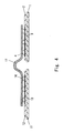
- FIG. 5A is a plan view of the semiconductor apparatus according to the third embodiment of the invention
- Fig. 5B is a cross sectional view along line X-X of Fig. 5A.
- the same elements as in the first embodiment are denoted by the same reference numerals and not described in detail herein.
- a connecting portion 27b formed at one end of the wire 27 and the lead 5 are electrically connected, and a connecting portion 27a formed at the other end of the wire 27 and the conductive bump 4 are also electrically connected.
- the wire 27 is made of Au, Cu, Ni, Ag, Al or Pd or an alloy mainly containing these. Although the wire 27 normally has a circular cross section, the both ends (the connecting portions 27a and 27b) of the wire 27 are flat-plate shaped in the example of Fig. 5 for easily laser welding of the lead 5 and the conductive bump 4.
- the connecting portion 27b of the wire 27 may be laser-welded with a conductive bump that is formed on an electrode pad of another semiconductor device, rather than with the lead 5, so that two semiconductor devices are connected through the wire 27.
- the thickness of the flat-plate shaped connecting portion 27a of the wire 27 is preferably 1 to 30 times the height of the conductive bump 4 for the same reason as in the first embodiment.
- the connecting portion 27b to be welded with the lead frame 14 is also flat-plate shaped.
- the method of manufacturing a semiconductor apparatus according to the third embodiment performs the laser welding of the connecting portion 27a and the conductive bump 4, thereby preventing mechanical damage to the semiconductor device 2. Further, with the use of the conductive bump 4, thermal damage to the semiconductor device 2 can be avoided by adjusting the height of the conductive bump 4 based on the thickness of the connecting portion 27a. It is thereby possible to provide a semiconductor apparatus with high reliability and productivity.
Landscapes
- Wire Bonding (AREA)
- Laser Beam Processing (AREA)
Applications Claiming Priority (1)
| Application Number | Priority Date | Filing Date | Title |
|---|---|---|---|
| JP2006115133A JP4722757B2 (ja) | 2006-04-19 | 2006-04-19 | 半導体装置の製造方法 |
Publications (2)
| Publication Number | Publication Date |
|---|---|
| EP1848030A2 true EP1848030A2 (fr) | 2007-10-24 |
| EP1848030A3 EP1848030A3 (fr) | 2010-08-25 |
Family
ID=38284010
Family Applications (1)
| Application Number | Title | Priority Date | Filing Date |
|---|---|---|---|
| EP07007105A Withdrawn EP1848030A3 (fr) | 2006-04-19 | 2007-04-04 | Procédé de fabrication d'un dispositif semi-conducteur |
Country Status (4)
| Country | Link |
|---|---|
| US (1) | US7820489B2 (fr) |
| EP (1) | EP1848030A3 (fr) |
| JP (1) | JP4722757B2 (fr) |
| CN (1) | CN101060090B (fr) |
Cited By (4)
| Publication number | Priority date | Publication date | Assignee | Title |
|---|---|---|---|---|
| CN106370169A (zh) * | 2016-11-15 | 2017-02-01 | 中国电子科技集团公司第二十六研究所 | 一种半球谐振陀螺敏感头高气密性激光封焊方法 |
| US9859680B2 (en) | 2013-12-17 | 2018-01-02 | Lasermax, Inc. | Shock resistant laser module |
| EP3236489A3 (fr) * | 2013-12-27 | 2018-01-10 | Pac Tech - Packaging Technologies GmbH | Procédé de fabrication d'un module de puce |
| EP3956924A1 (fr) * | 2019-04-18 | 2022-02-23 | Hitachi Energy Switzerland AG | Module semi-conducteur de puissance avec grille de connexion soudée par laser |
Families Citing this family (8)
| Publication number | Priority date | Publication date | Assignee | Title |
|---|---|---|---|---|
| US7977804B2 (en) * | 2008-05-16 | 2011-07-12 | Tektronix, Inc. | Ball-bump bonded ribbon-wire interconnect |
| JP5737412B2 (ja) * | 2011-09-15 | 2015-06-17 | 富士電機株式会社 | 半導体装置の製造方法およびその製造方法を用いて製造した半導体装置 |
| EP3008363A1 (fr) * | 2013-06-10 | 2016-04-20 | Federal-Mogul Corporation | Joint statique et son procédé de fabrication |
| JP2015144188A (ja) * | 2014-01-31 | 2015-08-06 | 株式会社東芝 | 半導体装置及びその製造方法 |
| CN106304630B (zh) * | 2015-06-09 | 2019-12-27 | 南京瀚宇彩欣科技有限责任公司 | 软性电路板及显示装置 |
| WO2018021322A1 (fr) * | 2016-07-26 | 2018-02-01 | 三菱電機株式会社 | Dispositif semi-conducteur |
| CN106298722B (zh) * | 2016-09-26 | 2019-10-11 | 无锡新洁能股份有限公司 | 一种大电流功率半导体器件的封装结构及制造方法 |
| CN109530838B (zh) * | 2018-12-13 | 2021-05-04 | 武汉凌云光电科技有限责任公司 | 一种激光焊接功率半导体芯片的方法 |
Family Cites Families (19)
| Publication number | Priority date | Publication date | Assignee | Title |
|---|---|---|---|---|
| JPS6153737A (ja) | 1984-08-24 | 1986-03-17 | Hitachi Ltd | 電子装置の組立法及び組立装置 |
| US4845335A (en) * | 1988-01-28 | 1989-07-04 | Microelectronics And Computer Technology Corporation | Laser Bonding apparatus and method |
| JPH07118514B2 (ja) * | 1989-04-24 | 1995-12-18 | 株式会社東芝 | 半田バンプ型半導体装置 |
| EP0470210A1 (fr) | 1989-07-03 | 1992-02-12 | General Electric Company | Module encapsule a faible inductance comprenant une puce a semi-conducteur |
| US4978835A (en) * | 1989-08-21 | 1990-12-18 | Microelectronics And Computer Technology Corporation | Method of clamping electrical contacts for laser bonding |
| US5164566A (en) * | 1990-06-12 | 1992-11-17 | Microelectronics And Computer Technology Corp. | Method and apparatus for fluxless solder reflow |
| JP3027512B2 (ja) | 1994-08-23 | 2000-04-04 | 株式会社日立製作所 | パワーmosfet |
| JP3285294B2 (ja) * | 1995-08-08 | 2002-05-27 | 太陽誘電株式会社 | 回路モジュールの製造方法 |
| US5731244A (en) * | 1996-05-28 | 1998-03-24 | Micron Technology, Inc. | Laser wire bonding for wire embedded dielectrics to integrated circuits |
| US5892270A (en) * | 1997-05-23 | 1999-04-06 | Samsung Electronics Co., Ltd. | Chip on board assembly without wire bonding |
| JP4169882B2 (ja) | 1999-08-30 | 2008-10-22 | Necエレクトロニクス株式会社 | 半導体装置およびその製造方法 |
| JP3574380B2 (ja) * | 2000-07-14 | 2004-10-06 | 新光電気工業株式会社 | 半導体装置、配線基板、半導体装置の実装方法、及び半導体装置の実装構造 |
| JP4112816B2 (ja) * | 2001-04-18 | 2008-07-02 | 株式会社東芝 | 半導体装置および半導体装置の製造方法 |
| JP3898459B2 (ja) | 2001-04-18 | 2007-03-28 | 加賀東芝エレクトロニクス株式会社 | 半導体装置の製造方法 |
| FR2835390B1 (fr) | 2002-01-31 | 2005-11-25 | Valeo Electronique | Procede et equipement de soudage de conducteurs sur des substrats |
| JP2004079760A (ja) * | 2002-08-19 | 2004-03-11 | Nec Electronics Corp | 半導体装置及びその組立方法 |
| JP2004119670A (ja) * | 2002-09-26 | 2004-04-15 | Yaskawa Electric Corp | パワー素子を用いた半導体装置 |
| JP4065799B2 (ja) | 2003-03-12 | 2008-03-26 | 株式会社ルネサステクノロジ | 超音波接合装置および方法 |
| JP4265394B2 (ja) * | 2003-12-17 | 2009-05-20 | 株式会社日立製作所 | 電力変換装置 |
-
2006
- 2006-04-19 JP JP2006115133A patent/JP4722757B2/ja not_active Expired - Fee Related
-
2007
- 2007-03-23 US US11/727,008 patent/US7820489B2/en not_active Expired - Fee Related
- 2007-04-04 EP EP07007105A patent/EP1848030A3/fr not_active Withdrawn
- 2007-04-13 CN CN2007100961155A patent/CN101060090B/zh not_active Expired - Fee Related
Cited By (7)
| Publication number | Priority date | Publication date | Assignee | Title |
|---|---|---|---|---|
| US9859680B2 (en) | 2013-12-17 | 2018-01-02 | Lasermax, Inc. | Shock resistant laser module |
| EP3236489A3 (fr) * | 2013-12-27 | 2018-01-10 | Pac Tech - Packaging Technologies GmbH | Procédé de fabrication d'un module de puce |
| US10354971B2 (en) | 2013-12-27 | 2019-07-16 | PAC Tech—Packaging Technologies GmbH | Method for producing a chip module |
| DE102013114907B4 (de) * | 2013-12-27 | 2025-10-23 | Pac Tech-Packaging Technologies Gmbh | Verfahren zur Herstellung eines Chipmoduls |
| CN106370169A (zh) * | 2016-11-15 | 2017-02-01 | 中国电子科技集团公司第二十六研究所 | 一种半球谐振陀螺敏感头高气密性激光封焊方法 |
| CN106370169B (zh) * | 2016-11-15 | 2019-09-27 | 中国电子科技集团公司第二十六研究所 | 一种半球谐振陀螺敏感头高气密性激光封焊方法 |
| EP3956924A1 (fr) * | 2019-04-18 | 2022-02-23 | Hitachi Energy Switzerland AG | Module semi-conducteur de puissance avec grille de connexion soudée par laser |
Also Published As
| Publication number | Publication date |
|---|---|
| US7820489B2 (en) | 2010-10-26 |
| EP1848030A3 (fr) | 2010-08-25 |
| CN101060090B (zh) | 2011-04-13 |
| JP2007288013A (ja) | 2007-11-01 |
| US20070249152A1 (en) | 2007-10-25 |
| CN101060090A (zh) | 2007-10-24 |
| JP4722757B2 (ja) | 2011-07-13 |
Similar Documents
| Publication | Publication Date | Title |
|---|---|---|
| US7820489B2 (en) | Method of manufacturing semiconductor apparatus | |
| US7772031B2 (en) | Semiconductor apparatus manufacturing method | |
| JP5090088B2 (ja) | 半導体装置およびその製造方法 | |
| US9905497B2 (en) | Resin sealing type semiconductor device and method of manufacturing the same, and lead frame | |
| US7812464B2 (en) | Semiconductor device and a method of manufacturing for high output MOSFET | |
| JP4260263B2 (ja) | 半導体装置 | |
| JP2010251374A (ja) | 半導体装置およびその製造方法 | |
| JP7594950B2 (ja) | 半導体装置 | |
| CN115148708A (zh) | 用于封装半导体装置的熔丝 | |
| US8378468B2 (en) | Semiconductor device and method of manufacturing the same | |
| JP2009224529A (ja) | 半導体装置およびその製造方法 | |
| JP2013102233A (ja) | 半導体装置 | |
| WO1991000617A1 (fr) | Module encapsule a faible inductance comprenant une puce a semi-conducteur | |
| JP2011151109A (ja) | 半導体装置およびその製造方法 | |
| US12532786B2 (en) | Semiconductor device package with vertically stacked passive component | |
| JP4357493B2 (ja) | 半導体装置 | |
| JP4357492B2 (ja) | 半導体装置 | |
| KR19980083259A (ko) | 칩 싸이즈 반도체 패키지의 구조 및 그 제조 방법 | |
| JP2011029492A (ja) | 電力用半導体装置 | |
| JPH09148494A (ja) | 樹脂封止型半導体装置 |
Legal Events
| Date | Code | Title | Description |
|---|---|---|---|
| PUAI | Public reference made under article 153(3) epc to a published international application that has entered the european phase |
Free format text: ORIGINAL CODE: 0009012 |
|
| AK | Designated contracting states |
Kind code of ref document: A2 Designated state(s): AT BE BG CH CY CZ DE DK EE ES FI FR GB GR HU IE IS IT LI LT LU LV MC MT NL PL PT RO SE SI SK TR |
|
| AX | Request for extension of the european patent |
Extension state: AL BA HR MK YU |
|
| PUAL | Search report despatched |
Free format text: ORIGINAL CODE: 0009013 |
|
| AK | Designated contracting states |
Kind code of ref document: A3 Designated state(s): AT BE BG CH CY CZ DE DK EE ES FI FR GB GR HU IE IS IT LI LT LU LV MC MT NL PL PT RO SE SI SK TR |
|
| AX | Request for extension of the european patent |
Extension state: AL BA HR MK RS |
|
| RAP1 | Party data changed (applicant data changed or rights of an application transferred) |
Owner name: RENESAS ELECTRONICS CORPORATION |
|
| 17P | Request for examination filed |
Effective date: 20110225 |
|
| AKX | Designation fees paid |
Designated state(s): DE |
|
| STAA | Information on the status of an ep patent application or granted ep patent |
Free format text: STATUS: THE APPLICATION HAS BEEN WITHDRAWN |
|
| 18W | Application withdrawn |
Effective date: 20130708 |