EP1848032A2 - Matériaux et procédés de formation de cavités contrôlées dans des couches diélectriques - Google Patents
Matériaux et procédés de formation de cavités contrôlées dans des couches diélectriques Download PDFInfo
- Publication number
- EP1848032A2 EP1848032A2 EP07251624A EP07251624A EP1848032A2 EP 1848032 A2 EP1848032 A2 EP 1848032A2 EP 07251624 A EP07251624 A EP 07251624A EP 07251624 A EP07251624 A EP 07251624A EP 1848032 A2 EP1848032 A2 EP 1848032A2
- Authority
- EP
- European Patent Office
- Prior art keywords
- groups
- layer
- sacrificial layer
- cyclic
- precursor
- Prior art date
- Legal status (The legal status is an assumption and is not a legal conclusion. Google has not performed a legal analysis and makes no representation as to the accuracy of the status listed.)
- Granted
Links
Images


Classifications
-
- H—ELECTRICITY
- H10—SEMICONDUCTOR DEVICES; ELECTRIC SOLID-STATE DEVICES NOT OTHERWISE PROVIDED FOR
- H10P—GENERIC PROCESSES OR APPARATUS FOR THE MANUFACTURE OR TREATMENT OF DEVICES COVERED BY CLASS H10
- H10P14/00—Formation of materials, e.g. in the shape of layers or pillars
- H10P14/60—Formation of materials, e.g. in the shape of layers or pillars of insulating materials
- H10P14/69—Inorganic materials
- H10P14/6902—Inorganic materials composed of carbon, e.g. alpha-C, diamond or hydrogen doped carbon
-
- H—ELECTRICITY
- H10—SEMICONDUCTOR DEVICES; ELECTRIC SOLID-STATE DEVICES NOT OTHERWISE PROVIDED FOR
- H10P—GENERIC PROCESSES OR APPARATUS FOR THE MANUFACTURE OR TREATMENT OF DEVICES COVERED BY CLASS H10
- H10P14/00—Formation of materials, e.g. in the shape of layers or pillars
- H10P14/60—Formation of materials, e.g. in the shape of layers or pillars of insulating materials
- H10P14/63—Formation of materials, e.g. in the shape of layers or pillars of insulating materials characterised by the formation processes
- H10P14/6326—Deposition processes
- H10P14/6328—Deposition from the gas or vapour phase
-
- H—ELECTRICITY
- H10—SEMICONDUCTOR DEVICES; ELECTRIC SOLID-STATE DEVICES NOT OTHERWISE PROVIDED FOR
- H10P—GENERIC PROCESSES OR APPARATUS FOR THE MANUFACTURE OR TREATMENT OF DEVICES COVERED BY CLASS H10
- H10P14/00—Formation of materials, e.g. in the shape of layers or pillars
- H10P14/60—Formation of materials, e.g. in the shape of layers or pillars of insulating materials
- H10P14/63—Formation of materials, e.g. in the shape of layers or pillars of insulating materials characterised by the formation processes
- H10P14/6326—Deposition processes
- H10P14/6342—Liquid deposition, e.g. spin-coating, sol-gel techniques or spray coating
-
- H—ELECTRICITY
- H10—SEMICONDUCTOR DEVICES; ELECTRIC SOLID-STATE DEVICES NOT OTHERWISE PROVIDED FOR
- H10P—GENERIC PROCESSES OR APPARATUS FOR THE MANUFACTURE OR TREATMENT OF DEVICES COVERED BY CLASS H10
- H10P14/00—Formation of materials, e.g. in the shape of layers or pillars
- H10P14/60—Formation of materials, e.g. in the shape of layers or pillars of insulating materials
- H10P14/66—Formation of materials, e.g. in the shape of layers or pillars of insulating materials characterised by the type of materials
- H10P14/668—Formation of materials, e.g. in the shape of layers or pillars of insulating materials characterised by the type of materials the materials being characterised by the deposition precursor materials
-
- H—ELECTRICITY
- H10—SEMICONDUCTOR DEVICES; ELECTRIC SOLID-STATE DEVICES NOT OTHERWISE PROVIDED FOR
- H10P—GENERIC PROCESSES OR APPARATUS FOR THE MANUFACTURE OR TREATMENT OF DEVICES COVERED BY CLASS H10
- H10P14/00—Formation of materials, e.g. in the shape of layers or pillars
- H10P14/60—Formation of materials, e.g. in the shape of layers or pillars of insulating materials
- H10P14/69—Inorganic materials
- H10P14/692—Inorganic materials composed of oxides, glassy oxides or oxide-based glasses
- H10P14/6938—Inorganic materials composed of oxides, glassy oxides or oxide-based glasses the material containing at least one metal element, e.g. metal oxides, metal oxynitrides or metal oxycarbides
-
- H—ELECTRICITY
- H10—SEMICONDUCTOR DEVICES; ELECTRIC SOLID-STATE DEVICES NOT OTHERWISE PROVIDED FOR
- H10P—GENERIC PROCESSES OR APPARATUS FOR THE MANUFACTURE OR TREATMENT OF DEVICES COVERED BY CLASS H10
- H10P34/00—Irradiation with electromagnetic or particle radiation of wafers, substrates or parts of devices
- H10P34/40—Irradiation with electromagnetic or particle radiation of wafers, substrates or parts of devices with high-energy radiation
-
- H—ELECTRICITY
- H10—SEMICONDUCTOR DEVICES; ELECTRIC SOLID-STATE DEVICES NOT OTHERWISE PROVIDED FOR
- H10P—GENERIC PROCESSES OR APPARATUS FOR THE MANUFACTURE OR TREATMENT OF DEVICES COVERED BY CLASS H10
- H10P50/00—Etching of wafers, substrates or parts of devices
- H10P50/60—Wet etching
- H10P50/64—Wet etching of semiconductor materials
- H10P50/642—Chemical etching
-
- H—ELECTRICITY
- H10—SEMICONDUCTOR DEVICES; ELECTRIC SOLID-STATE DEVICES NOT OTHERWISE PROVIDED FOR
- H10P—GENERIC PROCESSES OR APPARATUS FOR THE MANUFACTURE OR TREATMENT OF DEVICES COVERED BY CLASS H10
- H10P95/00—Generic processes or apparatus for manufacture or treatments not covered by the other groups of this subclass
- H10P95/90—Thermal treatments, e.g. annealing or sintering
-
- H—ELECTRICITY
- H10—SEMICONDUCTOR DEVICES; ELECTRIC SOLID-STATE DEVICES NOT OTHERWISE PROVIDED FOR
- H10W—GENERIC PACKAGES, INTERCONNECTIONS, CONNECTORS OR OTHER CONSTRUCTIONAL DETAILS OF DEVICES COVERED BY CLASS H10
- H10W10/00—Isolation regions in semiconductor bodies between components of integrated devices
- H10W10/01—Manufacture or treatment
- H10W10/021—Manufacture or treatment of air gaps
-
- H—ELECTRICITY
- H10—SEMICONDUCTOR DEVICES; ELECTRIC SOLID-STATE DEVICES NOT OTHERWISE PROVIDED FOR
- H10W—GENERIC PACKAGES, INTERCONNECTIONS, CONNECTORS OR OTHER CONSTRUCTIONAL DETAILS OF DEVICES COVERED BY CLASS H10
- H10W10/00—Isolation regions in semiconductor bodies between components of integrated devices
- H10W10/20—Air gaps
-
- H—ELECTRICITY
- H10—SEMICONDUCTOR DEVICES; ELECTRIC SOLID-STATE DEVICES NOT OTHERWISE PROVIDED FOR
- H10W—GENERIC PACKAGES, INTERCONNECTIONS, CONNECTORS OR OTHER CONSTRUCTIONAL DETAILS OF DEVICES COVERED BY CLASS H10
- H10W20/00—Interconnections in chips, wafers or substrates
- H10W20/01—Manufacture or treatment
- H10W20/071—Manufacture or treatment of dielectric parts thereof
- H10W20/072—Manufacture or treatment of dielectric parts thereof of dielectric parts comprising air gaps
-
- H—ELECTRICITY
- H10—SEMICONDUCTOR DEVICES; ELECTRIC SOLID-STATE DEVICES NOT OTHERWISE PROVIDED FOR
- H10W—GENERIC PACKAGES, INTERCONNECTIONS, CONNECTORS OR OTHER CONSTRUCTIONAL DETAILS OF DEVICES COVERED BY CLASS H10
- H10W20/00—Interconnections in chips, wafers or substrates
- H10W20/01—Manufacture or treatment
- H10W20/071—Manufacture or treatment of dielectric parts thereof
- H10W20/074—Manufacture or treatment of dielectric parts thereof of dielectric parts comprising thin functional dielectric layers, e.g. dielectric etch-stop, barrier, capping or liner layers
-
- H—ELECTRICITY
- H10—SEMICONDUCTOR DEVICES; ELECTRIC SOLID-STATE DEVICES NOT OTHERWISE PROVIDED FOR
- H10W—GENERIC PACKAGES, INTERCONNECTIONS, CONNECTORS OR OTHER CONSTRUCTIONAL DETAILS OF DEVICES COVERED BY CLASS H10
- H10W20/00—Interconnections in chips, wafers or substrates
- H10W20/40—Interconnections external to wafers or substrates, e.g. back-end-of-line [BEOL] metallisations or vias connecting to gate electrodes
- H10W20/45—Interconnections external to wafers or substrates, e.g. back-end-of-line [BEOL] metallisations or vias connecting to gate electrodes characterised by their insulating parts
- H10W20/46—Interconnections external to wafers or substrates, e.g. back-end-of-line [BEOL] metallisations or vias connecting to gate electrodes characterised by their insulating parts comprising air gaps
-
- H—ELECTRICITY
- H10—SEMICONDUCTOR DEVICES; ELECTRIC SOLID-STATE DEVICES NOT OTHERWISE PROVIDED FOR
- H10P—GENERIC PROCESSES OR APPARATUS FOR THE MANUFACTURE OR TREATMENT OF DEVICES COVERED BY CLASS H10
- H10P14/00—Formation of materials, e.g. in the shape of layers or pillars
- H10P14/60—Formation of materials, e.g. in the shape of layers or pillars of insulating materials
- H10P14/63—Formation of materials, e.g. in the shape of layers or pillars of insulating materials characterised by the formation processes
- H10P14/6326—Deposition processes
- H10P14/6328—Deposition from the gas or vapour phase
- H10P14/6334—Deposition from the gas or vapour phase using decomposition or reaction of gaseous or vapour phase compounds, i.e. chemical vapour deposition
- H10P14/6336—Deposition from the gas or vapour phase using decomposition or reaction of gaseous or vapour phase compounds, i.e. chemical vapour deposition in the presence of a plasma [PECVD]
-
- H—ELECTRICITY
- H10—SEMICONDUCTOR DEVICES; ELECTRIC SOLID-STATE DEVICES NOT OTHERWISE PROVIDED FOR
- H10P—GENERIC PROCESSES OR APPARATUS FOR THE MANUFACTURE OR TREATMENT OF DEVICES COVERED BY CLASS H10
- H10P14/00—Formation of materials, e.g. in the shape of layers or pillars
- H10P14/60—Formation of materials, e.g. in the shape of layers or pillars of insulating materials
- H10P14/66—Formation of materials, e.g. in the shape of layers or pillars of insulating materials characterised by the type of materials
- H10P14/665—Porous materials
-
- H—ELECTRICITY
- H10—SEMICONDUCTOR DEVICES; ELECTRIC SOLID-STATE DEVICES NOT OTHERWISE PROVIDED FOR
- H10P—GENERIC PROCESSES OR APPARATUS FOR THE MANUFACTURE OR TREATMENT OF DEVICES COVERED BY CLASS H10
- H10P14/00—Formation of materials, e.g. in the shape of layers or pillars
- H10P14/60—Formation of materials, e.g. in the shape of layers or pillars of insulating materials
- H10P14/66—Formation of materials, e.g. in the shape of layers or pillars of insulating materials characterised by the type of materials
- H10P14/668—Formation of materials, e.g. in the shape of layers or pillars of insulating materials characterised by the type of materials the materials being characterised by the deposition precursor materials
- H10P14/6681—Formation of materials, e.g. in the shape of layers or pillars of insulating materials characterised by the type of materials the materials being characterised by the deposition precursor materials the precursor containing a compound comprising Si
- H10P14/6684—Formation of materials, e.g. in the shape of layers or pillars of insulating materials characterised by the type of materials the materials being characterised by the deposition precursor materials the precursor containing a compound comprising Si the compound comprising silicon and oxygen
- H10P14/6686—Formation of materials, e.g. in the shape of layers or pillars of insulating materials characterised by the type of materials the materials being characterised by the deposition precursor materials the precursor containing a compound comprising Si the compound comprising silicon and oxygen the compound being a molecule comprising at least one silicon-oxygen bond and the compound having hydrogen or an organic group attached to the silicon or oxygen, e.g. a siloxane
-
- H—ELECTRICITY
- H10—SEMICONDUCTOR DEVICES; ELECTRIC SOLID-STATE DEVICES NOT OTHERWISE PROVIDED FOR
- H10P—GENERIC PROCESSES OR APPARATUS FOR THE MANUFACTURE OR TREATMENT OF DEVICES COVERED BY CLASS H10
- H10P14/00—Formation of materials, e.g. in the shape of layers or pillars
- H10P14/60—Formation of materials, e.g. in the shape of layers or pillars of insulating materials
- H10P14/69—Inorganic materials
- H10P14/692—Inorganic materials composed of oxides, glassy oxides or oxide-based glasses
- H10P14/6921—Inorganic materials composed of oxides, glassy oxides or oxide-based glasses containing silicon
- H10P14/6922—Inorganic materials composed of oxides, glassy oxides or oxide-based glasses containing silicon the material containing Si, O and at least one of H, N, C, F or other non-metal elements, e.g. SiOC, SiOC:H or SiONC
Definitions
- SiO 2 As a fabrication aid used to help fabricate silicon cantilever structures.
- the SiO 2 can be removed by etching in aqueous HF without affecting the silicon.
- aqueous solvents to remove the SiO 2 can cause collapsing of the small structures due to capillary effects, which arise during drying of the water, for example in cantilever fabrication.
- the selective etching of silicon versus SiO 2 by XeF 2 can be used for this fabrication by capping the silicon with a thin organic membrane through which the XeF 2 can be diffused.
- sacrificial materials in the microelectronics industry has been the use of a sacrificial organic material to introduce voids into an organosilicate glass (OSG) to make a porous OSG.
- OSG organosilicate glass
- the generation of these voids will effectively lower the dielectric constant of the material because the dielectric constant of air is 1.0, while the dielectric constant of the OSG material is generally >2.7.
- the lower limit for dielectric constant in microelectronic fabrication is achieved by incorporation of air gaps, which exhibit an effective dielectric constant of 1.0.
- the use of sacrificial organic layers is one promising way to realize this.
- Air gaps can be formed within the semiconductor substrate in a variety of different ways.
- One method to form the air gap within a device is through the deposition of a poorly conformal material, which when deposited on top of a substrate with a space between raised surfaces forms air gaps or voids between those surfaces.
- the air gap is formed within the spacing between a pair of interconnect lines, when the spacing is partially filled with a poorly conformal dielectric material, as shown in Fig 1.
- the poorly conformal dielectric material may be deposited, for example, by chemical vapor deposition or other means. This process, however, may not be amenable to the current dual damascene process used in copper integration, for example see 6,057,226 .
- U. S. Pat. Appln. No. 2002/0149085 disclose methods wherein the sacrificial material is comprised of a spin-on glass or chemical vapor deposited oxide-containing material with a high HF etch rate, that is capped with a bridge layer having an opening formed therein. The spun-on material is then removed through the opening using buffered HF. See this technique in Fig 2.
- U. S. Pat. Appln. Nos. US20040099951 A1 ; US20040094821A1 ; 2002/1016888 and 2002/002563 ; and U. S. Pat. Nos. 6,316,347 ; 6,329,279 ; and 6,498,070 ; 6,713,835 B1 ; 6,720,655 B1 disclose methods wherein the sacrificial material is an organic polymer capped by a bridge layer having one or more openings therein which is removed via a thermal anneal under an inert environment or "burning out" the polymer with an oxidizer such as molecular oxygen (O 2 ).
- an oxidizer such as molecular oxygen (O 2 ).
- the present invention is a process for forming an air gap within a substrate.
- the process comprises: providing a substrate; depositing a sacrificial layer with at least one organic precursor onto the substrate; depositing a layer of composite materials with a porogen, that is the same at least one organic precursor as in the sacrificial layer, and at least one silica-containing precursor or OSG precursor onto the substrate; and applying energy to the substrate having the sacrificial layer and the layer of composite materials to remove both the sacrificial layer to provide air gaps and the porogen to form a porous layer.
- the process comprises: providing a substrate; depositing a sacrificial layer comprising silicon; depositing a composite layer with a porogen and at least one silica-containing precursor or organosilicate glass(OSG) precursor; applying energy to the substrate having the sacrificial layer and the composite layer to remove the porogen to form a porous layer; and contacting the substrate having the sacrificial layer and the porous layer with a fluorine containing reagent under reduced pressure capable of diffusing through the porous layer to selectively remove the sacrificial layer to form air gaps.
- OSG organosilicate glass
- the process comprises: providing a substrate; depositing a polar solvent soluble metal oxide sacrificial layer with a metal precursor; depositing a composite layer with a porogen and at least one silica-containing precursor or organosilicate glass(OSG) precursor; applying energy to the substrate having the sacrificial layer and the composite layer to remove the porogen to form a porous layer; and contacting the substrate having the sacrificial layer and the porous layer with a polar solvent capable of diffusing through the porous layer to remove the sacrificial layer to form air gaps.
- OSG organosilicate glass
- the process comprises: providing a substrate; depositing a polar solvent soluble metal oxide sacrificial layer with a metal precursor; depositing a composite layer with a porogen, that is the same polar solvent soluble metal oxide as in the sacrificial layer, and at least one silica-containing precursor or organosilicate glass(OSG) precursor; contacting the substrate having the sacrificial layer and the composite layer with a polar solvent to remove the porogen to form a porous layer and to remove the sacrificial layer to form air gaps.
- interlayer dielectric (ILD) materials with ever lower dielectric constants.
- ILD interlayer dielectric
- a dense OSG film with a dielectric constant of 2.9 has a mechanical hardness of ⁇ 3.0 GPa
- a porous OSG material with ⁇ 25% porosity has a dielectric constant of 2.2, but a mechanical hardness of only 0.8 GPa. Extrapolating this trend to even lower dielectric constants, it is likely that a material with a dielectric constant below 1.9 may have a mechanical hardness of less than 0.3 GPa.
- Another trend observed is that: as the percent porosity increases there is a corresponding increase in the interconnect path length.
- the interconnect pathlength as measured by Positron Annihilation Lifetime Spectroscopy (PALS), is a measure of the longest distance a positronium element can travel without encountering a wall, or the longest string of connected pores. This interconnectedness is thought to be important for atomic layer deposition (ALD) considerations, as well as for interactions with wet processes such as resist developers, resist strippers and chemical mechanical planarization (CMP) slurries. Therefore, it is thought that at some point below a k of ⁇ 1.9 the ILD offers little in the way of mechanical or barrier resistance and the difference between a highly porous OSG film and an air gap begins to diminish.
- ALD atomic layer deposition
- CMP chemical mechanical planarization
- the present invention describes three alternative approaches for fabricating air gap, or void space, structures. All three routes utilize the ability of liquids or gases to diffuse through a porous OSG or SiO 2 layer.
- the porosity of this layer can range from 0.1 to 99 volume percent porosity, more generally from 10 - 50 volume% porosity.
- the first approach utilizes an organic sacrificial material to create the air gap. This is an extension of a porous dielectric layer using as an example the patented PDEMS TM product, which was developed for making porous OSG films. In this approach, the sacrificial layer and the porogen co-deposited with the OSG in the composite layer process are formed from the same organic precursor.
- a second approach similar to the first, employs a porous capping layer over a sacrificial material comprised of silicon.
- the sacrificial layer is covered with a composite layer either before or after patterning, and after the porogen is removed to yield a porous SiO 2 or OSG layer, the fabricated pieces is then exposed to a gas which will selectively etch silicon versus SiO 2 or OSG, such as XeF 2 or BrF 3 , which can diffuse through the porous SiO 2 or OSG layer to remove the silicon structure below leaving a void.
- the third method employs the use of a sacrificial inorganic material such as GeO 2 or B 2 O 3 , which is soluble in a polar solvent (i.e., water).
- a sacrificial inorganic material such as GeO 2 or B 2 O 3
- the sacrificial layer is covered with a composite layer either before or after patterning, and after the porogen is removed to yield a porous SiO 2 or OSG layer, the fabricated pieces are then exposed to water or other such polar solvent, which can diffuse through the porous SiO 2 or OSG layer to remove the soluble inorganic material (i.e. GeO 2 or B 2 O 3 ) leaving a void
- a surfactant to the water or polar solvent to enhance the diffusion through the porous layer, especially if the porous layer is a hydrophobic OSG material.
- R 1 can be independently H, C 1 to C 4 , linear or branched, saturated, singly or multiply unsaturated, cyclic, partially or fully fluorinated;
- R 2 can be independently C 1 to C 6 , linear or branched, saturated, singly or multiply unsaturated, cyclic, aromatic, partially or fully fluorinated, n is 1 to 3.
- R 1 and R 3 can be independently H, C 1 to C 4 , linear or branched, saturated, singly or multiply unsaturated, cyclic, partially or fully fluorinated
- R 2 and R 4 can be independently C 1 to C 6 , linear or branched, saturated, singly or multiply unsaturated, cyclic, aromatic, partially or fully fluorinated
- n is 1 to 3 and m is 1 to 3.
- R 1 can be independently H, C 1 to C 4 , linear or branched, saturated, singly or multiply unsaturated, cyclic, partially or fully fluorinated
- R 2 can be independently H, C 1 to C 6 , linear or branched, saturated, singly or multiply unsaturated, cyclic, aromatic, partially or fully fluorinated
- n is 1 to 3.
- R 1 and R 3 can be independently H, C 1 to C 4 , linear or branched, saturated, singly or multiply unsaturated, cyclic, partially or fully fluorinated
- R 2 and R 4 can be independently H, C 1 to C 6 , linear or branched, saturated, singly or multiply unsaturated, cyclic, aromatic, partially or fully fluorinated
- n is 1 to 3 and m is 1 to 3.
- R 1 and R 3 can be independently H, C 1 to C 4 , linear or branched, saturated, singly or multiply unsaturated, cyclic, partially or fully fluorinated;
- R 2 can be independently H, C 1 to C 6 , linear or branched, saturated, singly or multiply unsaturated, cyclic, aromatic, partially or fully fluorinated,
- R 4 can be independently C 1 to C 6 , linear or branched, saturated, singly or multiply unsaturated, cyclic, aromatic, partially or fully fluorinated, n is 1 to 3 and m is 1 to 3.
- R 1 and R 3 can be independently H, C 1 to C 4 , linear or branched, saturated, singly or multiply unsaturated, cyclic, partially or fully fluorinated
- R 2 can be independently H, C 1 to C 6 , linear or branched, saturated, singly or multiply unsaturated, cyclic, aromatic, partially or fully fluorinated
- R 4 can be independently C 1 to C 6 , linear or branched, saturated, singly or multiply unsaturated, cyclic, aromatic, partially or fully fluorinated
- n is 1 to 3 and m is 1 to 3.
- R 1 can be independently H, C 1 to C 4 , linear or branched, saturated, singly or multiply unsaturated, cyclic, partially or fully fluorinated
- R 2 can be independently C 1 to C 6 , linear or branched, saturated, singly or multiply unsaturated, cyclic, aromatic, partially or fully fluorinated
- R 4 can be independently H, C 1 to C 6 , linear or branched, saturated, singly or multiply unsaturated, cyclic, aromatic, partially or fully fluorinated
- n is 1 to 3 and p is 1 to 3.
- R 1 and R 3 can be independently H, C 1 to C 4 , linear or branched, saturated, singly or multiply unsaturated, cyclic, partially or fully fluorinated
- R 2 and R 6 can be independently C 1 to C 6 , linear or branched, saturated, singly or multiply unsaturated, cyclic, aromatic, partially or fully fluorinated
- R 4 and R 5 can be independently H, C 1 to C 6 , linear or branched, saturated, singly or multiply unsaturated, cyclic, aromatic, partially or fully fluorinated
- n is 1 to 3
- m is 1 to 3
- p is 1 to 3 and q is 1 to 3.
- R 1 and R 3 can be independently H, C 1 to C 4 , linear or branched, saturated, singly or multiply unsaturated, cyclic, partially or fully fluorinated
- R 2 , R 6 can be independently C 1 to C 6 , linear or branched, saturated, singly or multiply unsaturated, cyclic, aromatic, partially or fully fluorinated
- R 4 , R 5 can be independently H, C 1 to C 6 , linear or branched, saturated, singly or multiply unsaturated, cyclic, aromatic, partially or fully fluorinated
- n is 1 to 3
- m is 1 to 3
- p is 1 to 3 and q is 1
- TEOS triethoxysilane, di-tertiarybutoxysilane, silane, disilane, di-tertiarybutoxydiacetoxysilane.
- the present invention is directed to the use of a sacrificial material deposited by any of a plurality of traditional methods known in the electronics fabrication industry to be used as a sacrificial layer in the fabrication of a void space.
- This layer is particularly useful in the fabrication of air gap structures in the microelectronics industry and for "releasing" structures or fabricating void spaces in nanotechnology fabrication.
- the one or more air gaps are formed within at least a portion of the spacing between conductive lines within a layered substrate.
- conductive lines as used herein, relates generally to metal lines, traces, wire, interconnect lines, signal paths, or signaling medium that provide signal paths for coupling or interconnecting electrical circuitry within the substrate.
- the structure is readily scalable to multiple levels and is compatible with Single or Dual Damascene processing.
- dielectric layer may be a solid material or alternatively may be porous and/or contain voids, cavities or air-gaps.
- a sacrificial organic layer is used to create the void space.
- the at least one same organic precursor for deposition of both the sacrificial layer and for use as a porogen in the composite layer for example a PDEMS TM layer, it allows for a gradient to be built into the device.
- the same precursor is used as the organic precursor for the sacrificial layer and as the organic porogen precursor the PECVD process can be run initially using just the at least one organic precursor followed by flowing an additional at least one OSG precursor a seamless gradient can be formed between the sacrificial layer and the porous layer.
- 6,583,048 and 6,846,515 , 6,054,206 , 6,054,379 , 6,171,945 , and WO 99/41423 provide some exemplary CVD methods that may be used to form the organosilicate film of the present invention.
- the nature of the organic precursor used to deposit both the porogen in the composite layer and as the sacrificial layer has certain desirable attributes.
- the organic precursor should be able to be delivered into the reaction chamber in the gaseous form, therefore it is desirable that the organic precursor have a measurable vapor pressure at temperatures of 50° C or more. It is desirable that the organic precursor should react in the chamber in such a way that it forms a material which does not have a significant vapor pressure at temperatures of 100° C or more, more preferable, it is desirable that the porogen react to form a material which does not have an appreciable vapor pressure above 200° C.
- the number of degrees of unsaturation in an organic molecule are defined as the number of multiple bonds or the number of ring structures in the molecule. Thus a single double bond or a simple ring structure in a molecule is one degree of unsaturation while a triple bond or a double bond in a ring structure is two degrees of unsaturation.
- the number of degrees of unsaturation in the organic precursor will affect the deposition reaction, with higher number of degrees of unsaturation generally resulting in higher deposition rates. Without being limited by theory, however, it is generally observed that materials deposited from organic precursors with higher degrees of unsaturation are more difficult to remove completely, therefore a balance must be found between deposition and removal.
- a hetero-atom e.g. oxygen, nitrogen, or sulfur
- the hetero-atom will increase the electron capture cross section, and thus, increase the number of neutral radicals in the gas phase. This increase in the number of neutral radicals will increase the deposition efficiency, as the deposition is believed to be based on the reactions of neutral radicals.
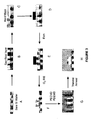
- FIG 3A-H and Example 4 This technique is illustrated in FIG 3A-H and Example 4 with regard to using the at least one same organic precursor to deposit both the sacrificial layer and the porogen in the composite layer.
- FIG 3A a bare silicon wafer is represented, although this could be at any stage in the fabrication of a microelectronic or nanotechnology device.
- the first step is the deposition of the sacrificial layer via PECVD utilizing the at least one organic precursor as shown in FIG 3B.
- a hard mask which can be any material which has good etch selectivity to photoresist and the sacrificial layer
- FIG 3C a composite film deposited from DEMS and Limonen is used as a hard mask is depicted.
- FIG 3E depicts the structure after the hard mask is etched away, this can be by for example RIE or wet etch.
- the pattern is transferred onto the sacrificial layer by, for example O 2 RIE as shown in FIG 3F, in this step it may be advantageous to engineer the etch rate and thickness of the pattern transfer material (i.e.
- a composite layer of PDEMS TM is then deposited over the top of this feature by PECVD as shown in FIG 3G, utilizing the same at least one organic precursor as was used to deposit the sacrificial layer, thus ensuring the ability of the sacrificial layer through the porous OSG layer.
- the porogen and sacrificial layer are removed by any of a number of techniques, the thermal annealing technique is described in FIG 3H.
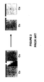
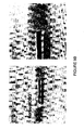
- FIG 9A shows the SEM photographs after thermal annealing to remove the sacrificial material leaving behind "tunnels" in the porous OSG network.
- One example of this type of fabrication would be to form a cantilever by depositing a layer of poly-silicon into SiO 2 on Silicon and then coating with a second layer of SiO 2 on top of the poly-silicon, after patterning and etching both the top SiO 2 layer and the poly-silicon layer the cantilever can be released by selectively etching the poly-silicon layer using XeF 2 .
- the poly-silicon is etched from the edges inward as the XeF 2 diffuses under the SiO 2 cantilever.
- the fluorine containing selective etching gas diffuses though a porous silicate or porous OSG capping layer which is formed over a poly- or amorphous-silicon layer to etch the underlying poly- or amorphous-silicon without having to open the structure and etch the underlying layer around the top layer (i.e without the need for lateral diffusion).
- a porous silicate or porous OSG capping layer which is formed over a poly- or amorphous-silicon layer to etch the underlying poly- or amorphous-silicon without having to open the structure and etch the underlying layer around the top layer (i.e without the need for lateral diffusion).
- the silicon layer can be removed without having to open a pathway for diffusion of the etch gas.
- Examples for possible uses for this technology are: formation of air gaps in semiconductor manufacturing, formation of tunnels for the delivery of gases or liquids for example for use in drug delivery by microcapillary fabrication, or for the formation of a hollow core in the fabrication of advanced fiber optic cables.
- the ability to build multiple layers of porous SiO 2 or porous OSG and silicon before the silicon is removed allows for the ability of fabricating interconnecting layers of microcapillaries which could interact in a manner similar to the circuitry in a microchip, especially for chemistry on a chip.
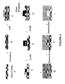
- FIG 4A-l shows an exemplary pathway for the formation of void.
- a silicon wafer (FIG 4A) is thermally oxidized in oxygen ambient to form a layer of SiO 2 which is necessary to prevent the selective fluorine etching gas from reacting with the silicon wafer itself (FIG 4B), if a non-silicon underlayer is used this step is not necessary.
- a layer of poly-silicon can be deposited for example using a high temperature thermal CVD from silane (FIG 4C).
- FIG 4E depicts the structure after the silicon layer is etched, this can be by for example RIE or using for example Cl 2 , or HBr.
- the pattern transfer material i.e. photoresist
- a number of different processes can be used in the ashing step, e.g.
- a O 2 reactive ion etching step a O 2 downstream ash, a reducing ash such as a H 2 or NH 3 downstream ash, or a UV assisted ash. These lines were then coated with a composite silica or OSG as shown in FIG 4G.
- any number of processes can be utilized to form this composite layer, for example: using a spin coater and Meso-ELK product (Air Products and Chemicals, Inc., Allentown, PA), as described in US Patents 6,365,266 ; 6,592,980 ; 6,818,289 and 6,942,918 ; or deposited via PECVD in a PDEM TM process (Air Products and Chemicals, Inc., Allentown, PA), as described in US Patent 6,583,048 and US Patent 6,846,515 .
- a spin coater and Meso-ELK product Air Products and Chemicals, Inc., Allentown, PA
- the porogen used to form the porous silica or porous OSG is then removed in an anneal step as shown in FIG 4H, this anneals step can be any number of processes, for example thermal annealing under an inert atmosphere, thermal annealing under an oxidizing atmosphere, thermal annealing under vacuum, reactive ion such as O 2 plasma, UV annealing under atmospheric or reducted pressures
- thermal annealing under an inert atmosphere thermal annealing under an oxidizing atmosphere
- thermal annealing under vacuum thermal annealing under vacuum, reactive ion such as O 2 plasma, UV annealing under atmospheric or reducted pressures
- BrF 3 10 Torr (1.3 kPa) and room temperature for a period of time as shown in FIG 41.
- etchants for silicon to form the air gap contemplated by the present invention include: HF, noble gas halides, interhalogens, such as IF 5 , BrCl 3 , IF 7 and CIF 3 .
- the selectivity of the BrF 3 and XeF 2 etching for silicon over SiO 2 or OSG is temperature dependant with lower temperatures resulting in greater selectivity.
- FIG 9B shows the SEM photographs after exposure of the structure to BrF 3 to remove the sacrificial silicon material leaving behind "tunnels" in the porous OSG network.
- the poly- or amorphous silicon layers could be etched into a pattern allowing for mixing of chemicals at given points along the wafer, by allowing for multiple layers of channels it could be possible to do multiple step synthesis of molecules on a single chip.
- the device Once the desired structure of porous silica or OSG and poly- or amorphous-silicon layers were fabricated the device would be exposed to selective fluorine containing etching gas in order to etch away the silicon to leave open channels. It may be advantageous to fill up the pores in the porous silica or OSG layers, if necessary, to prevent diffusion of the gases or liquids though the porous layer from one channel to another.
- RI refractive indexes
- To fabricate a hollow core fiber optic cable one could envision first forming a thin strand of poly-or amorphous-silicon and then coating this with a composite silica or OSG layer followed by removal of the porogen in an annealing step. The silicon core could then be etched away using a selective fluorine containing etching gas. It may be advantageous to then further coat this hollow core fiber with any of another layer in order to provide mechanical strength.
- GeO 2 germanium oxide
- B 2 O 3 boron oxide
- precursors for the formation of a water soluble metal oxide are materials such as, but not limited to, germanium (Ge) based precursors selected from tetra-methyl germane, germane, tetra-methoxy germanium and tetra-ethoxy germanium; and boron (B) based precursors selected from tri-methyl boron, trimethoxy borane, triethoxy borane and diborane.
- Ge germanium
- B boron
- SiO 2 and OSG films are not water soluble, but will allow for the diffusion of water through them thus allowing for the dissolution of the for example GeO 2 covered by a porous silicate or porous OSG layer.
- the present invention further proposes to use a porous silicate coating over a water soluble metal oxide layer to allow for the water to diffuse through the porous layer and etch the underlying water soluble metal oxide layer without having to etch the structure to expose the edge of the underlying layer.
- Examples for possible uses for this technology are: formation of air gaps in semiconductor manufacturing, formation of tunnels for the delivery of gases or liquids for example for use in drug delivery, or for the formation of a hollow core in the fabrication of advanced fiber optic cables.
- FIG 5A-1 shows an exemplary pathway for the formation of void spaces.
- a silicon wafer is coated with a layer of a water soluble metal oxide, for example GeO 2 (FIG 5A).
- a barrier layer such as layer of SiO 2 can be deposited using for example a PECVD process (FIG 4B), the barrier layer is used in this case to prevent dissolution of the water soluble metal oxide by aqueous tetramethylammonium hydroxide during photolithography to develop the resist pattern (FIG 5C), this layer may not be necessary if other pattern transfer techniques are used such as ink-jet or imprint lithography are employed.
- FIG 5D depicts the structure after the water soluble metal oxide is etched, this can be by for example RIE or using any of a number of fluorocarbons including CF 4 , C 4 F 6 , C 4 F 8 etc.
- the pattern transfer material i.e. photoresist
- a number of different processes can be used in the ashing step, e.g. a O 2 reactive ion etching step, a O 2 downstream ash, a reducing ash such as a H 2 or NH 3 downstream ash, or a UV assisted ash.
- These lines were then coated with a composite silica or OSG layer as shown in FIG5G.
- any number of processes can be utilized to form this composite layer, for example: using a spin coater and Meso-ELK product (Air Products and Chemicals, Inc., Allentown, PA), as described in US Patents 6,365,266 ; 6,592,980 ; 6,818,289 and 6,942,918 or deposited via PECVD in a PDEMS process (Air Products and Chemicals, Inc., Allentown, PA), as described in US Patent 6,583,048 and US Patent 6,846,515 .
- a spin coater and Meso-ELK product Air Products and Chemicals, Inc., Allentown, PA
- the porogen used to form the composite silica or porous OSG is then removed in an anneal step as shown in FIG 4H, this anneal step can be any number of processes, for example thermal annealing under an inert atmosphere, thermal annealing under an oxidizing atmosphere, thermal annealing under vacuum, reactive ion etching such as O 2 plasma, UV annealing under atmospheric or reducted pressures.
- these samples were then exposed to BrF 3 at 10 Torr (1.3 kPa) and room temperature for a period of time as shown in FIG 51.
- FIG 9C shows the SEM photographs after dissolution of a portion of the GeO 2 with water to remove the sacrificial water soluble metal oxide leaving behind "tunnels" in the porous OSG network.
- the mode would be similar to that for using the pure porogen as the sacrificial layer, except in this case the GeO 2 would be used as the sacrificial layer, in fact it may be possible to fabricate the entire semiconductor device before the air gaps are fabricated, this may offer some advantages in mechanical integrity during packaging which is a major issue for materials with low mechanical integrity.
- the GeO 2 layer could be etched into a pattern allowing for mixing of chemicals at given points along the wafer, by allowing for multiple layers of channels it could be possible to do multiple step synthesis of molecules on a single chip.
- RI refractive indexes
- To fabricate a hollow core fiber optic cable one could envision first forming a thin strand of GeO 2 and then coating this with a porous silica or OSG layer. The silicon core could then be dissolved away using water. It may be advantageous to then further coat this hollow core fiber with another layer in order to provide mechanical strength.
- B 2 O 3 can be used in place of GeO 2 as a water soluble metal oxide.
- Various polar solvents can be used in place of water, such as: alcohols, ethers, heteroatom containing molecules, esters, ketones, aldehydes and mixtures of such solvents.
- the sacrificial material and composite layers are deposited onto at least a portion of a substrate from a precursor composition or mixture using a variety of different methods. These methods may be used by themselves or in combination.
- Some examples of processes that may be used to form the organosilicate film include the following: thermal chemical vapor deposition, plasma enhanced chemical vapor deposition ("PECVD”), high density PECVD, photon assisted CVD, plasma-photon assisted (“PPECVD”), cryogenic chemical vapor deposition, chemical assisted vapor deposition, hot-filament chemical vapor deposition (aka iCVD, or cat-CVD), photo initiated chemical vapor deposition, CVD of a liquid polymer precursor, deposition from supercritical fluids, or transport polymerization ("TP").
- PECVD plasma enhanced chemical vapor deposition
- PECVD plasma enhanced chemical vapor deposition
- PECVD plasma-photon assisted
- cryogenic chemical vapor deposition chemical assisted vapor deposition
- hot-filament chemical vapor deposition aka
- the deposition is conducted at a temperature ranging from 100 to 425°C, preferably from 200 to 425°, and more preferably from 200 to 350°.
- the chemical reagents used herein may be sometimes described as "gaseous", it is understood that the chemical reagents may be delivered directly as a gas to the reactor, delivered as a vaporized liquid, a sublimed solid and/or transported by an inert carrier gas into the reactor.
- the sacrificial and composite materials are formed through a plasma-enhanced chemical vapor deposition process.
- chemical reagents are flowed into a reaction chamber such as a vacuum chamber and plasma energy energizes the chemical reagents thereby forming a film on at least a portion of the substrate.
- the layers of the substrate can be formed by the co-deposition, or alternatively the sequential deposition, of a gaseous mixture comprising at least one plasma-polymerizable organic material to form the sacrificial layer and at least one silica-containing precursor such as an organosilane or organosiloxane to form the composite layer.
- the plasma energy applied to the reagents may range from 0.02 to 7 watts/cm 2 , more preferably 0.3 to 3 watts/cm 2 .
- Flow rates for each of the reagents may ranges from 10 to 5000 sccm (standard cubic centimeters per minute, i.e. cm 3 /min at standard temperature and pressure).
- Pressure values in the vacuum chamber during deposition for a PECVD process of the present invention may range from 0.01 to 600 torr (1.3 Pa to 80 kPa), more preferably 1 to 10 torr (0.13 to 1.3 kPa). It is understood however that process parameters such as plasma energy, flow rate, and pressure may vary depending upon numerous factors such as the surface area of the substrate, and the equipment used in the PECVD process.
- additional materials can be charged into the vacuum chamber prior to, during and/or after the deposition reaction.
- Such materials include, e.g., inert gas (e.g., He, Ar, N 2 , Kr, Xe, which may be employed as a carrier gas for lesser volatile precursors and/or which can promote the curing of the as-deposited materials and provide a more stable final film) and reactive substances, such as gaseous or liquid organic substances, NH 3 , H 2 , CO 2 , CO, O 2 , or N 2 O.
- CO 2 is the preferred carrier gas.
- Energy is applied to the gaseous reagents to induce the gases to react and to form the film on the substrate.
- energy can be provided by, e.g., thermal, hot filament, plasma, pulsed plasma, helicon plasma, high-density plasma, inductively coupled plasma, and remote plasma methods.
- a secondary RF frequency source can be used to modify the plasma characteristics at the substrate surface.
- the film is formed by plasma enhanced chemical vapor deposition. It is particularly preferred to generate capacitively coupled plasma at a frequency of 13.56 MHz.
- Plasma power is preferably from 0.02 to 7 watts/cm 2 , more preferably 0.3 to 3 watts/cm 2 , based upon a surface area of the substrate.
- a carrier gas which possesses low ionization energy to lower the electron temperature in the plasma, which in turn will cause less fragmentation in the OSG precursor(s).
- this type of low ionization gas include CO 2 , NH 3 , CO, CH 4 , Ar, Xe, and Kr.
- the flow rate for each of the gaseous reagents preferably ranges from 10 to 5000 sccm, more preferably from 30 to 1000 sccm, per single 200 mm wafer.
- the individual rates are selected so as to provide the desired amounts of structure-former and pore-former in the film.
- the actual flow rates needed may depend upon wafer size and chamber configuration, and are in no way limited to 200 mm wafers or single wafer chambers.
- the film may be deposited at a deposition rate of at least 50 nm/min.
- the pressure in the vacuum chamber during deposition is preferably 0.01 to 600 torr (1.3 Pa to 80 kPa), more preferably 1 to 15 torr (0.13 to 2 kPa).
- the film is preferably deposited to a thickness of 0.002 to 10 microns, although the thickness can be varied as required.
- the blanket film deposited on a non-patterned surface has excellent uniformity, with a variation in thickness of less than 2% over 1 standard deviation across the substrate with a reasonable edge exclusion, wherein e.g., a 5mm outermost edge of the substrate is not included in the statistical calculation of uniformity.
- These films are generally formed by employing a spin-on technique using a mixture.
- the mixture generally comprises an at least one silica source and at least one porogen.
- the mixture may further include other constituents such as, but not limited to, water, solvent(s), catalyst, and/or ionic additives.
- the mixture comprises at least one silica source.
- a "silica source”, as used herein, is a compound having silicon (Si) and oxygen (O) and possibly additional substituents such as, but not limited to, other elements such as H, B, C, P, or halide atoms and organic groups such as alkyl groups; or aryl groups.
- alkyl as used herein includes linear, branched, or cyclic alkyl groups, containing from 1 to 24 carbon atoms, preferably from 1 to 12 carbon atoms, and more preferably from 1 to 5 carbon atoms. This term applies also to alkyl moieties contained in other groups such as haloalkyl, alkaryl, or aralkyl.
- alkyl further applies to alkyl moieties that are substituted, for example with carbonyl functionality.
- aryl as used herein applies to six to twelve member carbon rings having aromatic character.
- aryl also applies to aryl moieties that are substituted.
- the silica source may include materials that have a high number of Si-O bonds, but can further include Si-O-Si bridges, Si-R-Si bridges, Si-C bonds, Si-H bonds, Si-F bonds, or C-H bonds. It is preferred that the at least one silica source imparts a minimum of Si-OH bonds in the dielectric material.
- the mixture used to form the films of the present invention further comprises a porogen.
- a "porogen”, as used herein, is a reagent that is used to generate void volume within the resultant film.
- Suitable porogens for use in the composite materials of the present invention include labile organic groups, solvents, decomposable polymers, surfactants, dendrimers, hyper-branched polymers, polyoxyalkylene compounds, organic macromolecules, or combinations thereof. Still further examples of suitable porogens include those porogens described in pending patent application, Attorney Docket 06274P2, which is assigned to the assignee of the present invention.
- the porogen may include labile organic groups.
- the labile organic groups may contain sufficient oxygen to convert to gaseous products during the cure step.
- Some examples of compounds containing labile organic groups include the compounds disclosed in U. S. Pat. No. 6,171,945 .
- the porogen may be a solvent.
- the solvent is generally present during at least a portion of the cross-linking of the matrix material.
- Solvents typically used to aid in pore formation have relatively higher boiling points, i.e., greater than 175°C, preferably greater than 200°C.
- Solvents suitable for use as a porogen within the mixture of the present invention include those solvents provided, for example, in U. S. Pat. No. 6,231,989 .
- the porogen may be a small molecule such as those described in the reference Zheng, et al., "Synthesis of Mesoporous Silica Materials with Hydroxyacetic Acid Derivatives as Templates via a Sol-Gel Process", J. Inorg. Organomet. Polymers, 10, 103-113 (2000) .
- the porogen could also be a decomposable polymer.
- the decomposable polymer may be radiation decomposable, or more preferably, thermally decomposable.
- the term "polymer”, as used herein, also encompasses the terms oligomers and/or copolymers unless expressly stated to the contrary.
- Radiation decomposable polymers are polymers that decompose upon exposure to radiation, e.g., ultraviolet, X-ray, electron beam. Thermally decomposable polymers undergo thermal decomposition at temperatures that approach the condensation temperature of the silica source materials and are present during at least a portion of the cross-linking.
- Such polymers are those which foster templating of the vitrification reaction, control and define pore size, and decompose and diffuse out of the matrix at the appropriate time in processing.
- these polymers include polymers that have an architecture that provides a three-dimensional structure such as, but not limited to, block copolymers, i.e., diblock, triblock, and multiblock copolymers; star block copolymers; radial diblock copolymers; graft diblock copolymers; cografted copolymers; dendrigraft copolymers; tapered block copolymers; and combinations of these architectures.
- block copolymers i.e., diblock, triblock, and multiblock copolymers
- star block copolymers radial diblock copolymers
- graft diblock copolymers graft diblock copolymers
- cografted copolymers dendrigraft copolymers
- tapered block copolymers and combinations of these architectures.
- the porogen may be a hyper branched or dendrimeric polymer.
- Hyper branched and dendrimeric polymers generally have low solution and melt viscosities, high chemical reactivity due to surface functionality, and enhanced solubility even at higher molecular weights.
- suitable decomposable hyper-branched polymers and dendrimers are provided in " Comprehensive Polymer Science", 2nd Supplement, Aggarwal, pp. 71-132 (1996 ).
- the porogen within the film-forming mixture may also be a polyoxyalkylene compound such as polyoxyalkylene non-ionic surfactants, polyoxyalkylene polymers, polyoxyalkylene copolymers, polyoxyalkylene oligomers, or combinations thereof.
- a polyoxyalkylene compound such as polyoxyalkylene non-ionic surfactants, polyoxyalkylene polymers, polyoxyalkylene copolymers, polyoxyalkylene oligomers, or combinations thereof.
- An example of such is a polyalkylene oxide that includes an alkyl moiety ranging from C 2 to C 6 such as polyethylene oxide, polypropylene oxide, and copolymers thereof.
- the porogen of the present invention could also comprise a surfactant.
- a surfactant For silica sol-gel based films in which the porosity is introduced by the addition of surfactant that is subsequently removed, varying the amount of surfactant can vary porosity.
- Typical surfactants exhibit an amphiphilic nature, meaning that they can be both hydrophilic and hydrophobic at the same time.
- Amphiphilic surfactants possess a hydrophilic head group or groups, which have a strong affinity for water and a long hydrophobic tail that is organophilic and repels water.
- the surfactants can be anionic, cationic, nonionic, or amphoteric. Further classifications of surfactants include silicone surfactants, poly (alkylene oxide) surfactants, and fluorochemical surfactants.
- the mixture comprises, inter alia, at least one silica source, a porogen, a catalyst, an ionic additive, and water.
- the mixture further comprises a solvent and a surfactant.
- dispensing the mixture onto a substrate and evaporating the solvent and water can form the films.
- the surfactant and remaining solvent and water are generally removed by curing the coated substrate at one or more temperatures and for a time sufficient to produce the composite film.
- the coated substrate is then further heated or cured to form the porous SiO 2 or OSG film.
- Specific temperature and time durations will vary depending upon the ingredients within the mixture, the substrate, and the desired pore volume.
- the cure step is conducted at two or more temperatures rather than a controlled ramp or soak.
- the first temperature typically below 300°C, may be to remove the water and/or solvent from the mixture and for further cross-linking reactions.
- the second temperature may be to remove the porogen and to substantially, but not necessarily completely, cross-link the material.
- the organic porogen and sacrificial materials are removed by a curing step, which can comprise thermal annealing, chemical treatment, in-situ or remote plasma treating, electron beam treatment, photocuring and/or microwaving.
- a curing step which can comprise thermal annealing, chemical treatment, in-situ or remote plasma treating, electron beam treatment, photocuring and/or microwaving.
- Other in-situ or post-deposition treatments may be used to enhance the materials properties of the remaining porous SiO 2 or porous OSG such as hardness, stability (e.g. to shrinkage, to air exposure, to etching, to wet etching), integrability, uniformity and adhesion.
- Such treatments can be applied to the film prior to, during and/or after porogen removal using the same or different means used for porogen removal.
- post-treating denotes treating the film with energy (e.g., thermal, plasma, photon, electron, microwave) or chemicals to remove porogen, stabilize the film and/
- post-treating can be conducted under high pressure or under a vacuum ambient.
- Annealing is conducted under the following conditions.
- the environment can be inert (e.g., nitrogen, CO 2 , noble gases (He, Ar, Ne, Kr, Xe)), oxidizing (e.g., oxygen, air, dilute oxygen environments, enriched oxygen environments, ozone, nitrous oxide) or reducing (dilute or concentrated hydrogen, hydrocarbons (saturated, unsaturated, linear or branched, aromatics)).
- the pressure is preferably about 1 Torr (0.13 kPa) to about 1000 Torr (130 kPa).
- a vacuum ambient is also possible for thermal annealing as well as any other post-treating means.
- the temperature is preferably 200-500 °C, and the temperature ramp rate is from 0.1 to 100 deg °C/min.
- the total annealing time is preferably from 0.01 min to 12 hours.
- Plasma treating for selective removal of labile groups and possible chemical modification of the OSG film is conducted under the following conditions.
- the environment can be inert (e.g., nitrogen, CO 2 , noble gases (He, Ar, Ne, Kr, Xe)), oxidizing (e.g., oxygen, air, dilute oxygen environments, enriched oxygen environments, ozone, nitrous oxide), or reducing (e.g., dilute or concentrated hydrogen, hydrocarbons (saturated, unsaturated, linear or branched, aromatics)).
- the plasma power is preferably 0-5000 W.
- the temperature is preferably ambient to 500°C.
- the pressure is preferably 10 mtorr (1.3 Pa) to atmospheric pressure (1 atm; 100 kPa).
- the total curing time is preferably 0.01 min to 12 hours.
- Removal of the porogen and sacrificial organic material via UV exposure is conducted under the following conditions.
- the environment can be inert (e.g., nitrogen, CO 2 , noble gases (He, Ar, Ne, Kr, Xe)), oxidizing (e.g., oxygen, air, dilute oxygen environments, enriched oxygen environments, ozone, nitrous oxide), or reducing (e.g., dilute or concentrated hydrocarbons, hydrogen).
- the temperature is preferably ambient (eg. 20 to 25 °C) to 500°C.
- the power is preferably 0 to 5000 W.
- the wavelength is preferably IR, visible, UV or deep UV (wavelengths ⁇ 200nm).
- the total curing time is preferably 0.01 min to 12 hours.
- Removal of the porogen and sacrificial organic material via microwave exposure is conducted under the following conditions.
- the environment can be inert (e.g., nitrogen, CO 2 , noble gases (He, Ar, Ne, Kr, Xe)), oxidizing (e.g., oxygen, air, dilute oxygen environments, enriched oxygen environments, ozone, nitrous oxide), or reducing (e.g., dilute or concentrated hydrocarbons, hydrogen).
- the temperature is preferably ambient to 500°C.
- the power and wavelengths are varied and tunable to specific bonds.
- the total curing time is preferably from 0.01 min to 12 hours.
- Removal of the porogen and sacrificial organic material via electron beam exposure is conducted under the following conditions.
- the environment can be vacuum, inert (e.g., nitrogen, CO 2 , noble gases (He, Ar, Ne, Kr, Xe)), oxidizing (e.g., oxygen, air, dilute oxygen environments, enriched oxygen environments, ozone, nitrous oxide), or reducing (e.g., dilute or concentrated hydrocarbons, hydrogen).
- the temperature is preferably ambient to 500°C.
- the electron density and energy can be varied and tunable to specific bonds.
- the total curing time is preferably from 0.001 min to 12 hours, and may be continuous or pulsed. Additional guidance regarding the general use of electron beams is available in publications such as: S. Chattopadhyay et al., Journal of Materials Science, 36 (2001) 4323-4330 ; G.
- the use of electron beam treatment may provide for porogen removal and enhancement of film mechanical properties through bond-formation processes in matrix.
- Films of the invention may also contain fluorine, in the form of inorganic fluorine (e.g., Si-F). Fluorine, when present, is preferably contained in an amount ranging from 0.5 to 7 atomic%.
- the films are compatible with chemical mechanical planarization (CMP) and anisotropic etching, and are capable of adhering to a variety of materials, such as silicon, SiO 2 , Si 3 N 4 , OSG, FSG, silicon carbide, hydrogenated silicon carbide, silicon nitride, hydrogenated silicon nitride, silicon carbonitride, hydrogenated silicon carbonitride, boronitride, antireflective coatings, photoresists, organic polymers, porous organic and inorganic materials, metals such as copper and aluminum, and diffusion barrier layers such as but not limited to TiN, Ti(C)N TaN, Ta(C)N, Ta, W, WN or W(C)N.
- the films are preferably capable of adhering to at least one of the foregoing materials sufficiently to pass a conventional pull test, such as ASTM D3359-95a tape pull test. A sample is considered to have passed the test if there is no discernible removal of film.
- Products of the invention can be provided in any form capable of being deposited by CVD, such as coatings, multilaminar assemblies, and other types of objects that are not necessarily planar or thin, and a multitude of objects not necessarily used in integrated circuits.
- the substrate is a semiconductor.
- the present invention includes the process by which the products are made, methods of using the products and compounds and compositions useful for preparing the products.
- FIGS. 6A-G show a cross sectional view illustrating the steps of a method for forming a semiconductor substrate of the present invention.
- Fig. 6A shows a layer (40) of porogen plus SiO 2 or OSG on top of a layer of sacrificial materials (30). Underneath these layers is an already fabricated air gap interconnect level comprising at least a void space (10), a porous silica or OSG layer (20), a metallization layer (60), and copper metal (70) on top of a substrate (50).
- the top layer (40) consisting of at least porogen and silica or OSG is etched, preferably using photolithographic techniques.
- the via level can be etched into the sacrificial layer (30) using standard photolithographic techniques as shown in Fig 6C.
- a copper barrier layer (60) comprising at least one of Ta, TaN, Ru, Ti, TiN, TiSiN, is then deposited as shown in Fig. 6D.
- Copper (70) is then deposited by for example electroplating or electroless plating Fig. 6E, followed by CMP of the copper and barrier to form a planar structure Fig. 6F. Finally the porogen and sacrificial layers are removed as shown in Fig. 6G.
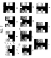
- the single damascene method shown in FIGS. 7A-7K allows the sacrificial layer to be formed between the metal lines.
- each layer is deposited and etched separately.
- the sacrificial layer (30) is deposited and etched in Fig's 7A and 7B.
- a copper barrier layer (60) comprising at least one of Ta, TaN, Ru, Ti, TiN, TiSiN, is then deposited as shown in Fig. 7C.
- Copper (70) is then deposited by for example electroplating or electroless plating Fig. 7D, followed by CMP of the copper and barrier to form a planar structure Fig. 7E.
- the composite silica or OSG layer with porogen (40) is then deposited (Fig. 7F) and etched (Fig.
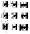
- Figs 8A - I show schematically how air gaps might be formed between metal lines using a Dual Damascene approach. Initially a composite silica or OSG layer with porogen (40) is deposited onto a substrate 50 as shown in Fig 8A. The porogen is then removed to yield a porous silica or OSG layer (20) as shown in Fig 8B. A sacrificial layer (30) is then deposited over the porous layer (20) as shown in FIG. 8C.
- the sacrificial layer and the porous layers are then etched using photolithographic techniques (Fig 8D-E), it may be necessary to use a hard mask at this step in order to enhance the etch and ash selectivity's between the sacrificial layer and the photoresist, especially if the sacrificial layer is an organic material.
- a copper barrier layer (60), comprising at least one of Ta, TaN, Ru, Ti, TiN, TiSiN, is then deposited as shown in Fig. 8F.
- Copper (70) is then deposited by for example electroplating or electroless plating Fig. 8G, followed by CMP of the copper and barrier to form a planar structure Fig. 8H.
- a composite layer of silica or OSG with porogen (40) is then deposited on top Fig 8I.
- etch stop layer an anti-reflective coating
- SiO 2 hardmask layer a TiN or other metal hardmask
- barrier layers Cu diffusion layers
- metal seed layers metal adhesion layers
- carbon hardmasks to assist in the delineation and fabrication of the structure.
- hard mask layer etch stop barrier layers, adhesion layers, adhesion promoters, stress buffers, etch post treatment, restoration chemistries, and sacrificial layers for trech-first of via-first dual damascene etch.
- Exemplary films were formed via a plasma enhanced CVD process using an Applied Materials Precision-5000 system in a 200 mm DxZ vacuum chamber that was fitted with an Advance Energy 200 rf generator from a variety of different chemical precursors and process conditions.
- the CVD process generally involved the following basic steps: initial set-up and stabilization of gas flows, deposition, and purge/evacuation of chamber prior to wafer removal.
- the thickness and refractive index of each film were measured on an SCI Filmtek 2000 Reflectometer.
- RIE reactive lon Etching
- etching was performed on an AMAT (Applied Materials & Technology Inc.) platform using standard RIE etch recipes.
- Photolithography was performed using a KarlSuss MA6 contact stepper at 365 nm and developed using standard TMAH (tetramethylammonium hydroxide) developer solutions. After RIE etching of the features the remaining photoresist was removed in an O 2 downstream ashing tool.
- TMAH tetramethylammonium hydroxide
- thermal post-deposition treatment or annealing was performed in an Applied Test Systems, Inc. Series 3210 tube furnace fitted with 4" (10cm) diameter purged quartz tube with a nitrogen flow ranging from 2 to 4 slpm (standard litres per minute, i.e. L/min at standard temperature and pressure). The ramp rate was 13°C per minute from 25 to 425°C. At 425°C, the films were soaked for 4 hours. The films were allowed to cool to below 100°C before removal from the furnace.
- Table I provides deposition conditions for the three exemplary sacrificial layers.
- Table I - Deposition Parameters of Various Organic Precursors Deposition Parameters Ex. 1: Decahydro-naphthalene (DHN) Ex. 2: 1,5-dimethyl-1,5-cyclooctadiene (DM-COD) Ex. 3: Alpha-terpinene (ATP) Ex.
- a sacrificial layer was deposited using the following recipe: 800 mg/min Limo liquid flow, 200 sccm CO 2 carrier gas flow, 350 milli-inch (8.9 mm) showerhead/wafer spacing, 250°C wafer chuck temperature, 8 Torr (1.07 kPa) chamber pressure for 360 seconds to yield a film with the following properties: 289 nm film thickness and a refractive index of 1.568.
- a composite layer was deposited atop the Limo sacrificial layer using the following recipe: 800 mg/min liquid flow (20/80 DEMS/Limo molar mixture), 220 sccm CO 2 carrier gas flow, 350 milli-inch (8.9 mm) showerhead/wafer spacing 250°C wafer chuck temperature, 8 Torr (1.07 kPa) chamber pressure for 60 seconds to yield a film with the following properties: 114 nm film thickness and a refractive index of 1.439.
- This wafer was then coated with 500 nm of Shipley 1805 resist and developed using a KarlSuss MA6 contact stepper at 365 nm, 12 mW/cm 2 for 1 second exposure. The pattern was then developed using TMAH.
- This patterned wafer was then etched using the following sequence: first a 6 second high density O 2 plasma to clear the pattern, followed by a 60 second etch using a C 4 F 8 /O 2 /Ar etch recipe which has an etch rate of 140 nm/minute to clear the hard mask, followed by a second O 2 plasma for 24 seconds to etch away the photoresist on top of the hard mask as well as etching the sacrificial limonene layer.
- a capping composite layer was then deposited using the following recipe: 800 mg/min liquid flow (20/80 DEMS/Limo molar mixture), 220 sccm CO 2 carrier gas flow, 350 milli-inch (8.9 mm) showerhead/wafer spacing 250°C wafer chuck temperature, 8 Torr (1.07 kPa) chamber pressure for 180 seconds to yield a film with the following properties: 362 nm film thickness and a refractive index of 1.439
- the fabrication of an air gap using selective etching of a silicon feature began by thermally oxidizing a bare silicon wafer to provide an etch stop for the XeF 2 / BrF 3 selective etching.
- a 0.5 micron thick layer of poly-silicon was grown via high temperature (900 °C) CVD process using silane, other types of silicon such as amorphous silicon could also be used.
- the poly-silicon was patterned using standard photolithography techniques and a BCl 3 based RIE process.
- the photoresist was ashed in a O 2 plasma and the patterned poly-silicon features were then coated with a composite OSG layer using Air Products' proprietary Meso-ELK TM spin-on porous OSG process.
- the stack was then calcined at 400 C in air to remove the porogen.
- the sample was exposed to 10 Torr (1.33 kPa) of BrF 3 at room temperature for 1 hour.
- the BrF 3 diffused through the Meso-ELK structure and selectively etched the silicon feature.
- SEM pictures of the air gap formed after selective etching of the silicon layer using BrF 3 are shown in FIG. 9B.
- XeF 2 can also be used for this fabrication process.
- Fabrication of an air gap using a water soluble sacrificial layer started with the deposition of a 1.2 micron layer of GeO 2 onto a silicon wafer.
- PECVD was used to deposit the GeO 2 from Me 4 Ge and O 2 , although other germanium based precursors, such as Ge(OEt) 4 , could also have been used.
- a layer of SiO 2 was deposited on top of the GeO 2 using Me 4 Si plus O 2 to act as a moisture barrier during TMAH developing of the photoresist, again many different SiO 2 or OSG precursors could be used for the moisture barrier.
- the photoresist was patterned and developed the SiO 2 /GeO 2 stack was etched in a CF 4 /Ar/O 2 RIE process.
- the SiO 2 cap can remain or be removed in a timed CF 4 /Ar/O 2 RIE process, in this example the cap was removed in a timed etch.
- the patterned GeO 2 was then coated with a composite OSG layer using Air Products' proprietary Meso-ELK TM spin-on porous OSG process.
- the composite layer was calcined at 400° C in air to remove the porogen.
- After coating with the porous OSG the film was dipped in water for 10 minutes during which time the GeO 2 dissolved away.
- a SEM cross-section of the partially dissolved GeO 2 sacrificial layer under a porous OSG layer is shown in FIG 9C. This process could also have been carried out using B 2 O 3 or other water soluble metal oxide materials as the sacrificial material using a similar scheme
- the technology of the present invention was successful in fabricating air gap structures using three different sacrificial materials.
- the first material was a labile organic sacrificial material, which was the same labile material used to create pores in the porous OSG layer, this unity allows for the creation of the structure.
- the same PECVD chamber could be used for both layers, and one annealing step could be used to both create the air gap and create the porous OSG through which the by-products from the air gap creation diffuses.
- Another advantage with this process was that the PECVD deposition processes could be carrier out at temperatures >250 °C, which allows for a more dimensionally stable sacrificial material relative to a spin-on polymer.
- the second sacrificial material was a water soluble GeO 2 structure.
- Using an inorganic material as the sacrificial material gave the structure more mechanical strength and allowed for the use of more standard etch processes in the fabrication of the structure.
- One difficulty with GeO 2 or B 2 O 3 in the fabrication of air gaps was the sensitivity to wet processes such as: developers, strippers, Cu deposition and CMP. If the GeO 2 /B 2 O3 structure can be protected from these processes by hard masks or Cu barriers, then GeO 2 /B 2 O 3 offers unique advantages, due to thermal robustness and mechanical strength.
- the final successful sacrificial material was silicon. Silicon could be used because of the selective nature of the XeF 2 or BrF 3 thermal etching for silicon versus SiO 2 or OSG, and the ability to deposit any of a number of porous OSG layers, for example using PDEMS TM or Meso-ELK porous dielectrics. Again, using an inorganic sacrificial layer gave the structure more mechanical strength during fabrication and allowed for more standard anisotropic etch processes.
Landscapes
- Internal Circuitry In Semiconductor Integrated Circuit Devices (AREA)
- Formation Of Insulating Films (AREA)
- Chemical Vapour Deposition (AREA)
- Chemical & Material Sciences (AREA)
- Chemical Kinetics & Catalysis (AREA)
- General Chemical & Material Sciences (AREA)
- Physics & Mathematics (AREA)
- Engineering & Computer Science (AREA)
- Plasma & Fusion (AREA)
- Manufacture Of Porous Articles, And Recovery And Treatment Of Waste Products (AREA)
Applications Claiming Priority (2)
| Application Number | Priority Date | Filing Date | Title |
|---|---|---|---|
| US79279306P | 2006-04-18 | 2006-04-18 | |
| US11/693,707 US8399349B2 (en) | 2006-04-18 | 2007-03-29 | Materials and methods of forming controlled void |
Publications (3)
| Publication Number | Publication Date |
|---|---|
| EP1848032A2 true EP1848032A2 (fr) | 2007-10-24 |
| EP1848032A3 EP1848032A3 (fr) | 2012-02-29 |
| EP1848032B1 EP1848032B1 (fr) | 2017-03-01 |
Family
ID=38322643
Family Applications (1)
| Application Number | Title | Priority Date | Filing Date |
|---|---|---|---|
| EP07251624.8A Not-in-force EP1848032B1 (fr) | 2006-04-18 | 2007-04-18 | Matériaux et procédés de formation de cavités contrôlées dans des couches diélectriques |
Country Status (6)
| Country | Link |
|---|---|
| US (3) | US8399349B2 (fr) |
| EP (1) | EP1848032B1 (fr) |
| JP (2) | JP4838190B2 (fr) |
| KR (1) | KR100859178B1 (fr) |
| CN (2) | CN101060095B (fr) |
| TW (1) | TWI395268B (fr) |
Cited By (1)
| Publication number | Priority date | Publication date | Assignee | Title |
|---|---|---|---|---|
| EP2117042A1 (fr) * | 2008-05-06 | 2009-11-11 | Commissariat A L'energie Atomique | Procede de realisation de cavites d'air dans des microstructures, notamment du type structures d'interconnexions a cavites d'air pour circuit integre |
Families Citing this family (400)
| Publication number | Priority date | Publication date | Assignee | Title |
|---|---|---|---|---|
| US7943412B2 (en) * | 2001-12-10 | 2011-05-17 | International Business Machines Corporation | Low temperature Bi-CMOS compatible process for MEMS RF resonators and filters |
| US6949456B2 (en) * | 2002-10-31 | 2005-09-27 | Asm Japan K.K. | Method for manufacturing semiconductor device having porous structure with air-gaps |
| US8399349B2 (en) * | 2006-04-18 | 2013-03-19 | Air Products And Chemicals, Inc. | Materials and methods of forming controlled void |
| JP2008258488A (ja) * | 2007-04-06 | 2008-10-23 | Oki Electric Ind Co Ltd | 半導体装置の製造方法 |
| KR100891146B1 (ko) * | 2007-07-30 | 2009-04-06 | 한국과학기술원 | 계층적 기공구조물 및 계층적 기공구조물을 이용한초소수성 및 초친수성 표면 제조방법 |
| FR2926397B1 (fr) * | 2008-01-16 | 2010-02-12 | Commissariat Energie Atomique | Procede de fabrication de films dielectriques permeables |
| FR2926396B1 (fr) * | 2008-01-16 | 2010-03-19 | Commissariat Energie Atomique | Procede de fabrication de films de carbure de silicium hydrogene amorphe munis de pores traversants et films ainsi obtenus |
| US8030218B2 (en) | 2008-03-21 | 2011-10-04 | Micron Technology, Inc. | Method for selectively modifying spacing between pitch multiplied structures |
| US8310053B2 (en) | 2008-04-23 | 2012-11-13 | Taiwan Semiconductor Manufacturing Company, Ltd. | Method of manufacturing a device with a cavity |
| US9790343B2 (en) | 2008-06-12 | 2017-10-17 | Avery Dennison Corporation | Porous material and method for producing the same |
| US20090324928A1 (en) * | 2008-06-26 | 2009-12-31 | Vijayakumar Ramachandrarao | Forming ultra low dielectric constant porous dielectric films and structures formed thereby |
| US10378106B2 (en) | 2008-11-14 | 2019-08-13 | Asm Ip Holding B.V. | Method of forming insulation film by modified PEALD |
| FR2942465B1 (fr) * | 2009-02-25 | 2011-03-18 | Univ Lille Sciences Tech | Procede de fabrication de microcanaux sur un support, et support comprenant de tels microcanaux |
| US7855123B2 (en) * | 2009-03-31 | 2010-12-21 | Tokyo Electron Limited | Method of integrating an air gap structure with a substrate |
| US9394608B2 (en) | 2009-04-06 | 2016-07-19 | Asm America, Inc. | Semiconductor processing reactor and components thereof |
| US20120119641A1 (en) * | 2009-05-14 | 2012-05-17 | Yijian Shi | Output efficiency of organic light emitting devices |
| US8802201B2 (en) | 2009-08-14 | 2014-08-12 | Asm America, Inc. | Systems and methods for thin-film deposition of metal oxides using excited nitrogen-oxygen species |
| CN102714396B (zh) * | 2010-01-29 | 2014-12-10 | 惠普发展公司,有限责任合伙企业 | 多模垂直腔表面发射激光器阵列 |
| US8642252B2 (en) | 2010-03-10 | 2014-02-04 | International Business Machines Corporation | Methods for fabrication of an air gap-containing interconnect structure |
| US9312155B2 (en) | 2011-06-06 | 2016-04-12 | Asm Japan K.K. | High-throughput semiconductor-processing apparatus equipped with multiple dual-chamber modules |
| CN102427053A (zh) * | 2011-06-17 | 2012-04-25 | 上海华力微电子有限公司 | 预防超低介电常数薄膜损伤的方法 |
| US10854498B2 (en) | 2011-07-15 | 2020-12-01 | Asm Ip Holding B.V. | Wafer-supporting device and method for producing same |
| US20130023129A1 (en) | 2011-07-20 | 2013-01-24 | Asm America, Inc. | Pressure transmitter for a semiconductor processing environment |
| US9017481B1 (en) | 2011-10-28 | 2015-04-28 | Asm America, Inc. | Process feed management for semiconductor substrate processing |
| ES2692653T3 (es) | 2012-08-21 | 2018-12-04 | Avery Dennison Corporation | Sistemas y métodos para fabricar películas, fibras, esferas y otros artículos porosos |
| US8833171B2 (en) * | 2012-08-23 | 2014-09-16 | Nxp, B.V. | Pressure sensor |
| US9659799B2 (en) | 2012-08-28 | 2017-05-23 | Asm Ip Holding B.V. | Systems and methods for dynamic semiconductor process scheduling |
| US10714315B2 (en) | 2012-10-12 | 2020-07-14 | Asm Ip Holdings B.V. | Semiconductor reaction chamber showerhead |
| US20160376700A1 (en) | 2013-02-01 | 2016-12-29 | Asm Ip Holding B.V. | System for treatment of deposition reactor |
| WO2014158351A1 (fr) * | 2013-03-13 | 2014-10-02 | Applied Materials, Inc. | Post-traitement pour la réduction de constante avec génération de pores sur des pellicules diélectriques à faible k |
| CN103641509B (zh) * | 2013-12-09 | 2016-02-10 | 中国建筑材料科学研究总院 | 一种反应烧结用多孔碳预制体及其制备方法与应用 |
| US20150206798A1 (en) * | 2014-01-17 | 2015-07-23 | Taiwan Semiconductor Manufacturing Company, Ltd. | Interconnect Structure And Method of Forming |
| US10683571B2 (en) | 2014-02-25 | 2020-06-16 | Asm Ip Holding B.V. | Gas supply manifold and method of supplying gases to chamber using same |
| CN104902678B (zh) * | 2014-03-07 | 2018-02-02 | 鹏鼎控股(深圳)股份有限公司 | 柔性印刷电路板及其制作方法 |
| US10167557B2 (en) | 2014-03-18 | 2019-01-01 | Asm Ip Holding B.V. | Gas distribution system, reactor including the system, and methods of using the same |
| US11015245B2 (en) | 2014-03-19 | 2021-05-25 | Asm Ip Holding B.V. | Gas-phase reactor and system having exhaust plenum and components thereof |
| KR20150136387A (ko) * | 2014-05-27 | 2015-12-07 | 삼성전자주식회사 | 반도체 소자의 제조 방법 |
| US9607881B2 (en) | 2014-06-20 | 2017-03-28 | Taiwan Semiconductor Manufacturing Company, Ltd. | Insulator void aspect ratio tuning by selective deposition |
| US10858737B2 (en) | 2014-07-28 | 2020-12-08 | Asm Ip Holding B.V. | Showerhead assembly and components thereof |
| US9890456B2 (en) | 2014-08-21 | 2018-02-13 | Asm Ip Holding B.V. | Method and system for in situ formation of gas-phase compounds |
| WO2016043481A1 (fr) * | 2014-09-15 | 2016-03-24 | 한국생산기술연구원 | Procédé de fabrication d'un film mince poreux de métal ou d'oxyde de métal ayant une structure de réseau ouvert tridimensionnel par l'intermédiaire d'un ajustement de la taille de pore dans un processus par voie sèche et film mince poreux de métal ou d'oxyde métallique ayant une structure de réseau ouvert tridimensionnel fabriqué par ce dernier |
| US10941490B2 (en) | 2014-10-07 | 2021-03-09 | Asm Ip Holding B.V. | Multiple temperature range susceptor, assembly, reactor and system including the susceptor, and methods of using the same |
| US9657845B2 (en) | 2014-10-07 | 2017-05-23 | Asm Ip Holding B.V. | Variable conductance gas distribution apparatus and method |
| US9847249B2 (en) * | 2014-11-05 | 2017-12-19 | Sandisk Technologies Llc | Buried etch stop layer for damascene bit line formation |
| KR102263121B1 (ko) | 2014-12-22 | 2021-06-09 | 에이에스엠 아이피 홀딩 비.브이. | 반도체 소자 및 그 제조 방법 |
| US10096485B2 (en) | 2015-02-19 | 2018-10-09 | Toshiba Memory Corporation | Semiconductor device and method of manufacturing the same |
| US10529542B2 (en) | 2015-03-11 | 2020-01-07 | Asm Ip Holdings B.V. | Cross-flow reactor and method |
| US10276355B2 (en) | 2015-03-12 | 2019-04-30 | Asm Ip Holding B.V. | Multi-zone reactor, system including the reactor, and method of using the same |
| US9576894B2 (en) * | 2015-06-03 | 2017-02-21 | GlobalFoundries, Inc. | Integrated circuits including organic interlayer dielectric layers and methods for fabricating the same |
| US10458018B2 (en) | 2015-06-26 | 2019-10-29 | Asm Ip Holding B.V. | Structures including metal carbide material, devices including the structures, and methods of forming same |
| US9941157B2 (en) | 2015-06-26 | 2018-04-10 | Taiwan Semiconductor Manufacturing Company, Ltd. | Porogen bonded gap filling material in semiconductor manufacturing |
| US10600673B2 (en) | 2015-07-07 | 2020-03-24 | Asm Ip Holding B.V. | Magnetic susceptor to baseplate seal |
| US9960072B2 (en) | 2015-09-29 | 2018-05-01 | Asm Ip Holding B.V. | Variable adjustment for precise matching of multiple chamber cavity housings |
| US10211308B2 (en) | 2015-10-21 | 2019-02-19 | Asm Ip Holding B.V. | NbMC layers |
| US9842734B2 (en) * | 2015-12-21 | 2017-12-12 | Imec Vzw | Method of forming a feature of a target material on a substrate |
| US11139308B2 (en) | 2015-12-29 | 2021-10-05 | Asm Ip Holding B.V. | Atomic layer deposition of III-V compounds to form V-NAND devices |
| DK3407724T3 (da) | 2016-01-26 | 2020-09-28 | Dow Global Technologies Llc | Sammensætning omfattende glutenfrit mel og hydroxypropylmethylcellulose |
| US10224235B2 (en) * | 2016-02-05 | 2019-03-05 | Lam Research Corporation | Systems and methods for creating airgap seals using atomic layer deposition and high density plasma chemical vapor deposition |
| US10468251B2 (en) | 2016-02-19 | 2019-11-05 | Asm Ip Holding B.V. | Method for forming spacers using silicon nitride film for spacer-defined multiple patterning |
| US10529554B2 (en) | 2016-02-19 | 2020-01-07 | Asm Ip Holding B.V. | Method for forming silicon nitride film selectively on sidewalls or flat surfaces of trenches |
| WO2017146737A1 (fr) * | 2016-02-26 | 2017-08-31 | Intel Corporation | Interconnexions par trou d'interconnexion dans des conditionnements de substrat |
| US10343920B2 (en) | 2016-03-18 | 2019-07-09 | Asm Ip Holding B.V. | Aligned carbon nanotubes |
| TWI717346B (zh) * | 2016-04-13 | 2021-02-01 | 大陸商盛美半導體設備(上海)股份有限公司 | 阻擋層的去除方法和半導體結構的形成方法 |
| US10190213B2 (en) | 2016-04-21 | 2019-01-29 | Asm Ip Holding B.V. | Deposition of metal borides |
| US10865475B2 (en) | 2016-04-21 | 2020-12-15 | Asm Ip Holding B.V. | Deposition of metal borides and silicides |
| US10367080B2 (en) | 2016-05-02 | 2019-07-30 | Asm Ip Holding B.V. | Method of forming a germanium oxynitride film |
| US10032628B2 (en) | 2016-05-02 | 2018-07-24 | Asm Ip Holding B.V. | Source/drain performance through conformal solid state doping |
| US11453943B2 (en) | 2016-05-25 | 2022-09-27 | Asm Ip Holding B.V. | Method for forming carbon-containing silicon/metal oxide or nitride film by ALD using silicon precursor and hydrocarbon precursor |
| US10388509B2 (en) | 2016-06-28 | 2019-08-20 | Asm Ip Holding B.V. | Formation of epitaxial layers via dislocation filtering |
| US9859151B1 (en) | 2016-07-08 | 2018-01-02 | Asm Ip Holding B.V. | Selective film deposition method to form air gaps |
| US10612137B2 (en) | 2016-07-08 | 2020-04-07 | Asm Ip Holdings B.V. | Organic reactants for atomic layer deposition |
| US10714385B2 (en) | 2016-07-19 | 2020-07-14 | Asm Ip Holding B.V. | Selective deposition of tungsten |
| US9812320B1 (en) | 2016-07-28 | 2017-11-07 | Asm Ip Holding B.V. | Method and apparatus for filling a gap |
| US9887082B1 (en) | 2016-07-28 | 2018-02-06 | Asm Ip Holding B.V. | Method and apparatus for filling a gap |
| KR102532607B1 (ko) | 2016-07-28 | 2023-05-15 | 에이에스엠 아이피 홀딩 비.브이. | 기판 가공 장치 및 그 동작 방법 |
| US10395919B2 (en) | 2016-07-28 | 2019-08-27 | Asm Ip Holding B.V. | Method and apparatus for filling a gap |
| US10581003B2 (en) | 2016-09-02 | 2020-03-03 | The Board of Trustee of the Leland Stanford Junior Universtiy | Method for lithograghic patterning of sensitive materials |
| US10410943B2 (en) | 2016-10-13 | 2019-09-10 | Asm Ip Holding B.V. | Method for passivating a surface of a semiconductor and related systems |
| US10643826B2 (en) | 2016-10-26 | 2020-05-05 | Asm Ip Holdings B.V. | Methods for thermally calibrating reaction chambers |
| US11532757B2 (en) | 2016-10-27 | 2022-12-20 | Asm Ip Holding B.V. | Deposition of charge trapping layers |
| US10714350B2 (en) | 2016-11-01 | 2020-07-14 | ASM IP Holdings, B.V. | Methods for forming a transition metal niobium nitride film on a substrate by atomic layer deposition and related semiconductor device structures |
| US10435790B2 (en) | 2016-11-01 | 2019-10-08 | Asm Ip Holding B.V. | Method of subatmospheric plasma-enhanced ALD using capacitively coupled electrodes with narrow gap |
| US10229833B2 (en) | 2016-11-01 | 2019-03-12 | Asm Ip Holding B.V. | Methods for forming a transition metal nitride film on a substrate by atomic layer deposition and related semiconductor device structures |
| US10134757B2 (en) | 2016-11-07 | 2018-11-20 | Asm Ip Holding B.V. | Method of processing a substrate and a device manufactured by using the method |
| KR102546317B1 (ko) | 2016-11-15 | 2023-06-21 | 에이에스엠 아이피 홀딩 비.브이. | 기체 공급 유닛 및 이를 포함하는 기판 처리 장치 |
| US10340135B2 (en) | 2016-11-28 | 2019-07-02 | Asm Ip Holding B.V. | Method of topologically restricted plasma-enhanced cyclic deposition of silicon or metal nitride |
| KR102762543B1 (ko) | 2016-12-14 | 2025-02-05 | 에이에스엠 아이피 홀딩 비.브이. | 기판 처리 장치 |
| US11447861B2 (en) | 2016-12-15 | 2022-09-20 | Asm Ip Holding B.V. | Sequential infiltration synthesis apparatus and a method of forming a patterned structure |
| US11581186B2 (en) | 2016-12-15 | 2023-02-14 | Asm Ip Holding B.V. | Sequential infiltration synthesis apparatus |
| KR102700194B1 (ko) | 2016-12-19 | 2024-08-28 | 에이에스엠 아이피 홀딩 비.브이. | 기판 처리 장치 |
| US10269558B2 (en) | 2016-12-22 | 2019-04-23 | Asm Ip Holding B.V. | Method of forming a structure on a substrate |
| US10867788B2 (en) | 2016-12-28 | 2020-12-15 | Asm Ip Holding B.V. | Method of forming a structure on a substrate |
| US11390950B2 (en) | 2017-01-10 | 2022-07-19 | Asm Ip Holding B.V. | Reactor system and method to reduce residue buildup during a film deposition process |
| US10655221B2 (en) | 2017-02-09 | 2020-05-19 | Asm Ip Holding B.V. | Method for depositing oxide film by thermal ALD and PEALD |
| US10468261B2 (en) | 2017-02-15 | 2019-11-05 | Asm Ip Holding B.V. | Methods for forming a metallic film on a substrate by cyclical deposition and related semiconductor device structures |
| US10529563B2 (en) | 2017-03-29 | 2020-01-07 | Asm Ip Holdings B.V. | Method for forming doped metal oxide films on a substrate by cyclical deposition and related semiconductor device structures |
| KR102457289B1 (ko) | 2017-04-25 | 2022-10-21 | 에이에스엠 아이피 홀딩 비.브이. | 박막 증착 방법 및 반도체 장치의 제조 방법 |
| US10446393B2 (en) | 2017-05-08 | 2019-10-15 | Asm Ip Holding B.V. | Methods for forming silicon-containing epitaxial layers and related semiconductor device structures |
| US10770286B2 (en) | 2017-05-08 | 2020-09-08 | Asm Ip Holdings B.V. | Methods for selectively forming a silicon nitride film on a substrate and related semiconductor device structures |
| US10892156B2 (en) | 2017-05-08 | 2021-01-12 | Asm Ip Holding B.V. | Methods for forming a silicon nitride film on a substrate and related semiconductor device structures |
| WO2018212007A1 (fr) * | 2017-05-19 | 2018-11-22 | 昭和電工株式会社 | Procédé de production électrochimique de germane |
| JP7030114B2 (ja) * | 2017-05-19 | 2022-03-04 | 昭和電工株式会社 | 電気化学的にゲルマンを製造する方法 |
| JP7030115B2 (ja) * | 2017-05-19 | 2022-03-04 | 昭和電工株式会社 | 電気化学的にゲルマンを製造する方法 |
| US10504742B2 (en) | 2017-05-31 | 2019-12-10 | Asm Ip Holding B.V. | Method of atomic layer etching using hydrogen plasma |
| US10886123B2 (en) | 2017-06-02 | 2021-01-05 | Asm Ip Holding B.V. | Methods for forming low temperature semiconductor layers and related semiconductor device structures |
| US12040200B2 (en) | 2017-06-20 | 2024-07-16 | Asm Ip Holding B.V. | Semiconductor processing apparatus and methods for calibrating a semiconductor processing apparatus |
| US11306395B2 (en) | 2017-06-28 | 2022-04-19 | Asm Ip Holding B.V. | Methods for depositing a transition metal nitride film on a substrate by atomic layer deposition and related deposition apparatus |
| US10685834B2 (en) | 2017-07-05 | 2020-06-16 | Asm Ip Holdings B.V. | Methods for forming a silicon germanium tin layer and related semiconductor device structures |
| KR20190009245A (ko) | 2017-07-18 | 2019-01-28 | 에이에스엠 아이피 홀딩 비.브이. | 반도체 소자 구조물 형성 방법 및 관련된 반도체 소자 구조물 |
| TWI762194B (zh) * | 2017-07-18 | 2022-04-21 | 美商應用材料股份有限公司 | 在金屬材料表面上沉積阻擋層的方法 |
| US11374112B2 (en) | 2017-07-19 | 2022-06-28 | Asm Ip Holding B.V. | Method for depositing a group IV semiconductor and related semiconductor device structures |
| US11018002B2 (en) | 2017-07-19 | 2021-05-25 | Asm Ip Holding B.V. | Method for selectively depositing a Group IV semiconductor and related semiconductor device structures |
| US10541333B2 (en) | 2017-07-19 | 2020-01-21 | Asm Ip Holding B.V. | Method for depositing a group IV semiconductor and related semiconductor device structures |
| US10590535B2 (en) | 2017-07-26 | 2020-03-17 | Asm Ip Holdings B.V. | Chemical treatment, deposition and/or infiltration apparatus and method for using the same |
| US10605530B2 (en) | 2017-07-26 | 2020-03-31 | Asm Ip Holding B.V. | Assembly of a liner and a flange for a vertical furnace as well as the liner and the vertical furnace |
| US10361137B2 (en) * | 2017-07-31 | 2019-07-23 | Taiwan Semiconductor Manufacturing Company, Ltd. | Semiconductor device and method |
| TWI815813B (zh) | 2017-08-04 | 2023-09-21 | 荷蘭商Asm智慧財產控股公司 | 用於分配反應腔內氣體的噴頭總成 |
| US10770336B2 (en) | 2017-08-08 | 2020-09-08 | Asm Ip Holding B.V. | Substrate lift mechanism and reactor including same |
| US10692741B2 (en) | 2017-08-08 | 2020-06-23 | Asm Ip Holdings B.V. | Radiation shield |
| US11139191B2 (en) | 2017-08-09 | 2021-10-05 | Asm Ip Holding B.V. | Storage apparatus for storing cassettes for substrates and processing apparatus equipped therewith |
| US11769682B2 (en) | 2017-08-09 | 2023-09-26 | Asm Ip Holding B.V. | Storage apparatus for storing cassettes for substrates and processing apparatus equipped therewith |
| US10249524B2 (en) | 2017-08-09 | 2019-04-02 | Asm Ip Holding B.V. | Cassette holder assembly for a substrate cassette and holding member for use in such assembly |
| USD900036S1 (en) | 2017-08-24 | 2020-10-27 | Asm Ip Holding B.V. | Heater electrical connector and adapter |
| US11830730B2 (en) | 2017-08-29 | 2023-11-28 | Asm Ip Holding B.V. | Layer forming method and apparatus |
| KR102491945B1 (ko) | 2017-08-30 | 2023-01-26 | 에이에스엠 아이피 홀딩 비.브이. | 기판 처리 장치 |
| US11295980B2 (en) | 2017-08-30 | 2022-04-05 | Asm Ip Holding B.V. | Methods for depositing a molybdenum metal film over a dielectric surface of a substrate by a cyclical deposition process and related semiconductor device structures |
| US11056344B2 (en) | 2017-08-30 | 2021-07-06 | Asm Ip Holding B.V. | Layer forming method |
| KR102401446B1 (ko) | 2017-08-31 | 2022-05-24 | 에이에스엠 아이피 홀딩 비.브이. | 기판 처리 장치 |
| US10607895B2 (en) | 2017-09-18 | 2020-03-31 | Asm Ip Holdings B.V. | Method for forming a semiconductor device structure comprising a gate fill metal |
| KR102630301B1 (ko) | 2017-09-21 | 2024-01-29 | 에이에스엠 아이피 홀딩 비.브이. | 침투성 재료의 순차 침투 합성 방법 처리 및 이를 이용하여 형성된 구조물 및 장치 |
| US10844484B2 (en) | 2017-09-22 | 2020-11-24 | Asm Ip Holding B.V. | Apparatus for dispensing a vapor phase reactant to a reaction chamber and related methods |
| US10658205B2 (en) | 2017-09-28 | 2020-05-19 | Asm Ip Holdings B.V. | Chemical dispensing apparatus and methods for dispensing a chemical to a reaction chamber |
| US10403504B2 (en) | 2017-10-05 | 2019-09-03 | Asm Ip Holding B.V. | Method for selectively depositing a metallic film on a substrate |
| US10319588B2 (en) | 2017-10-10 | 2019-06-11 | Asm Ip Holding B.V. | Method for depositing a metal chalcogenide on a substrate by cyclical deposition |
| US10923344B2 (en) | 2017-10-30 | 2021-02-16 | Asm Ip Holding B.V. | Methods for forming a semiconductor structure and related semiconductor structures |
| CN107703029B (zh) * | 2017-11-07 | 2019-05-10 | 大连理工大学 | 一种结合ct与pvt计算co2盐水扩散系数的方法 |
| KR102443047B1 (ko) | 2017-11-16 | 2022-09-14 | 에이에스엠 아이피 홀딩 비.브이. | 기판 처리 장치 방법 및 그에 의해 제조된 장치 |
| US10910262B2 (en) | 2017-11-16 | 2021-02-02 | Asm Ip Holding B.V. | Method of selectively depositing a capping layer structure on a semiconductor device structure |
| US11022879B2 (en) | 2017-11-24 | 2021-06-01 | Asm Ip Holding B.V. | Method of forming an enhanced unexposed photoresist layer |
| JP7214724B2 (ja) | 2017-11-27 | 2023-01-30 | エーエスエム アイピー ホールディング ビー.ブイ. | バッチ炉で利用されるウェハカセットを収納するための収納装置 |
| TWI791689B (zh) | 2017-11-27 | 2023-02-11 | 荷蘭商Asm智慧財產控股私人有限公司 | 包括潔淨迷你環境之裝置 |
| US10157773B1 (en) * | 2017-11-28 | 2018-12-18 | Taiwan Semiconductor Manufacturing Co., Ltd. | Semiconductor structure having layer with re-entrant profile and method of forming the same |
| US10872771B2 (en) | 2018-01-16 | 2020-12-22 | Asm Ip Holding B. V. | Method for depositing a material film on a substrate within a reaction chamber by a cyclical deposition process and related device structures |
| TWI799494B (zh) | 2018-01-19 | 2023-04-21 | 荷蘭商Asm 智慧財產控股公司 | 沈積方法 |
| KR102695659B1 (ko) | 2018-01-19 | 2024-08-14 | 에이에스엠 아이피 홀딩 비.브이. | 플라즈마 보조 증착에 의해 갭 충진 층을 증착하는 방법 |
| USD903477S1 (en) | 2018-01-24 | 2020-12-01 | Asm Ip Holdings B.V. | Metal clamp |
| US11018047B2 (en) | 2018-01-25 | 2021-05-25 | Asm Ip Holding B.V. | Hybrid lift pin |
| US10535516B2 (en) | 2018-02-01 | 2020-01-14 | Asm Ip Holdings B.V. | Method for depositing a semiconductor structure on a surface of a substrate and related semiconductor structures |
| USD880437S1 (en) | 2018-02-01 | 2020-04-07 | Asm Ip Holding B.V. | Gas supply plate for semiconductor manufacturing apparatus |
| US11081345B2 (en) | 2018-02-06 | 2021-08-03 | Asm Ip Holding B.V. | Method of post-deposition treatment for silicon oxide film |
| US10896820B2 (en) | 2018-02-14 | 2021-01-19 | Asm Ip Holding B.V. | Method for depositing a ruthenium-containing film on a substrate by a cyclical deposition process |
| US11685991B2 (en) | 2018-02-14 | 2023-06-27 | Asm Ip Holding B.V. | Method for depositing a ruthenium-containing film on a substrate by a cyclical deposition process |
| US10731249B2 (en) | 2018-02-15 | 2020-08-04 | Asm Ip Holding B.V. | Method of forming a transition metal containing film on a substrate by a cyclical deposition process, a method for supplying a transition metal halide compound to a reaction chamber, and related vapor deposition apparatus |
| KR102636427B1 (ko) | 2018-02-20 | 2024-02-13 | 에이에스엠 아이피 홀딩 비.브이. | 기판 처리 방법 및 장치 |
| US10658181B2 (en) | 2018-02-20 | 2020-05-19 | Asm Ip Holding B.V. | Method of spacer-defined direct patterning in semiconductor fabrication |
| US10975470B2 (en) | 2018-02-23 | 2021-04-13 | Asm Ip Holding B.V. | Apparatus for detecting or monitoring for a chemical precursor in a high temperature environment |
| US11473195B2 (en) | 2018-03-01 | 2022-10-18 | Asm Ip Holding B.V. | Semiconductor processing apparatus and a method for processing a substrate |
| US11629406B2 (en) | 2018-03-09 | 2023-04-18 | Asm Ip Holding B.V. | Semiconductor processing apparatus comprising one or more pyrometers for measuring a temperature of a substrate during transfer of the substrate |
| US11114283B2 (en) | 2018-03-16 | 2021-09-07 | Asm Ip Holding B.V. | Reactor, system including the reactor, and methods of manufacturing and using same |
| KR102646467B1 (ko) | 2018-03-27 | 2024-03-11 | 에이에스엠 아이피 홀딩 비.브이. | 기판 상에 전극을 형성하는 방법 및 전극을 포함하는 반도체 소자 구조 |
| JP7323317B2 (ja) * | 2018-03-28 | 2023-08-08 | 日東電工株式会社 | 下塗層形成用組成物、下塗層、及び塗膜 |
| US10510536B2 (en) | 2018-03-29 | 2019-12-17 | Asm Ip Holding B.V. | Method of depositing a co-doped polysilicon film on a surface of a substrate within a reaction chamber |
| US11088002B2 (en) | 2018-03-29 | 2021-08-10 | Asm Ip Holding B.V. | Substrate rack and a substrate processing system and method |
| US11230766B2 (en) | 2018-03-29 | 2022-01-25 | Asm Ip Holding B.V. | Substrate processing apparatus and method |
| KR102501472B1 (ko) | 2018-03-30 | 2023-02-20 | 에이에스엠 아이피 홀딩 비.브이. | 기판 처리 방법 |
| KR102600229B1 (ko) | 2018-04-09 | 2023-11-10 | 에이에스엠 아이피 홀딩 비.브이. | 기판 지지 장치, 이를 포함하는 기판 처리 장치 및 기판 처리 방법 |
| US12025484B2 (en) | 2018-05-08 | 2024-07-02 | Asm Ip Holding B.V. | Thin film forming method |
| TWI843623B (zh) | 2018-05-08 | 2024-05-21 | 荷蘭商Asm Ip私人控股有限公司 | 藉由循環沉積製程於基板上沉積氧化物膜之方法及相關裝置結構 |
| US12272527B2 (en) | 2018-05-09 | 2025-04-08 | Asm Ip Holding B.V. | Apparatus for use with hydrogen radicals and method of using same |
| KR20190129718A (ko) | 2018-05-11 | 2019-11-20 | 에이에스엠 아이피 홀딩 비.브이. | 기판 상에 피도핑 금속 탄화물 막을 형성하는 방법 및 관련 반도체 소자 구조 |
| CN108550527B (zh) * | 2018-05-16 | 2021-01-22 | 京东方科技集团股份有限公司 | 一种图形化方法 |
| JP2019200369A (ja) * | 2018-05-18 | 2019-11-21 | ジオマテック株式会社 | 表面微細構造の形成方法及び表面微細構造を備える物品 |
| KR102596988B1 (ko) | 2018-05-28 | 2023-10-31 | 에이에스엠 아이피 홀딩 비.브이. | 기판 처리 방법 및 그에 의해 제조된 장치 |
| US11718913B2 (en) | 2018-06-04 | 2023-08-08 | Asm Ip Holding B.V. | Gas distribution system and reactor system including same |
| TWI840362B (zh) | 2018-06-04 | 2024-05-01 | 荷蘭商Asm Ip私人控股有限公司 | 水氣降低的晶圓處置腔室 |
| US11286562B2 (en) | 2018-06-08 | 2022-03-29 | Asm Ip Holding B.V. | Gas-phase chemical reactor and method of using same |
| US10797133B2 (en) | 2018-06-21 | 2020-10-06 | Asm Ip Holding B.V. | Method for depositing a phosphorus doped silicon arsenide film and related semiconductor device structures |
| KR102568797B1 (ko) | 2018-06-21 | 2023-08-21 | 에이에스엠 아이피 홀딩 비.브이. | 기판 처리 시스템 |
| TWI871083B (zh) | 2018-06-27 | 2025-01-21 | 荷蘭商Asm Ip私人控股有限公司 | 用於形成含金屬材料之循環沉積製程 |
| US11499222B2 (en) | 2018-06-27 | 2022-11-15 | Asm Ip Holding B.V. | Cyclic deposition methods for forming metal-containing material and films and structures including the metal-containing material |
| US10612136B2 (en) | 2018-06-29 | 2020-04-07 | ASM IP Holding, B.V. | Temperature-controlled flange and reactor system including same |
| KR102686758B1 (ko) | 2018-06-29 | 2024-07-18 | 에이에스엠 아이피 홀딩 비.브이. | 박막 증착 방법 및 반도체 장치의 제조 방법 |
| US10388513B1 (en) | 2018-07-03 | 2019-08-20 | Asm Ip Holding B.V. | Method for depositing silicon-free carbon-containing film as gap-fill layer by pulse plasma-assisted deposition |
| US10755922B2 (en) | 2018-07-03 | 2020-08-25 | Asm Ip Holding B.V. | Method for depositing silicon-free carbon-containing film as gap-fill layer by pulse plasma-assisted deposition |
| US10767789B2 (en) | 2018-07-16 | 2020-09-08 | Asm Ip Holding B.V. | Diaphragm valves, valve components, and methods for forming valve components |
| US10483099B1 (en) | 2018-07-26 | 2019-11-19 | Asm Ip Holding B.V. | Method for forming thermally stable organosilicon polymer film |
| US11053591B2 (en) | 2018-08-06 | 2021-07-06 | Asm Ip Holding B.V. | Multi-port gas injection system and reactor system including same |
| US10883175B2 (en) | 2018-08-09 | 2021-01-05 | Asm Ip Holding B.V. | Vertical furnace for processing substrates and a liner for use therein |
| US10950426B2 (en) * | 2018-08-14 | 2021-03-16 | Taiwan Semiconductor Manufacturing Co., Ltd. | Dielectric layer, interconnection structure using the same, and manufacturing method thereof |
| US10829852B2 (en) | 2018-08-16 | 2020-11-10 | Asm Ip Holding B.V. | Gas distribution device for a wafer processing apparatus |
| US11430674B2 (en) | 2018-08-22 | 2022-08-30 | Asm Ip Holding B.V. | Sensor array, apparatus for dispensing a vapor phase reactant to a reaction chamber and related methods |
| US11024523B2 (en) | 2018-09-11 | 2021-06-01 | Asm Ip Holding B.V. | Substrate processing apparatus and method |
| KR102707956B1 (ko) | 2018-09-11 | 2024-09-19 | 에이에스엠 아이피 홀딩 비.브이. | 박막 증착 방법 |
| US11049751B2 (en) | 2018-09-14 | 2021-06-29 | Asm Ip Holding B.V. | Cassette supply system to store and handle cassettes and processing apparatus equipped therewith |
| CN110970344B (zh) | 2018-10-01 | 2024-10-25 | Asmip控股有限公司 | 衬底保持设备、包含所述设备的系统及其使用方法 |
| US11232963B2 (en) | 2018-10-03 | 2022-01-25 | Asm Ip Holding B.V. | Substrate processing apparatus and method |
| KR102592699B1 (ko) | 2018-10-08 | 2023-10-23 | 에이에스엠 아이피 홀딩 비.브이. | 기판 지지 유닛 및 이를 포함하는 박막 증착 장치와 기판 처리 장치 |
| US10847365B2 (en) | 2018-10-11 | 2020-11-24 | Asm Ip Holding B.V. | Method of forming conformal silicon carbide film by cyclic CVD |
| US10811256B2 (en) | 2018-10-16 | 2020-10-20 | Asm Ip Holding B.V. | Method for etching a carbon-containing feature |
| KR102546322B1 (ko) | 2018-10-19 | 2023-06-21 | 에이에스엠 아이피 홀딩 비.브이. | 기판 처리 장치 및 기판 처리 방법 |
| KR102605121B1 (ko) | 2018-10-19 | 2023-11-23 | 에이에스엠 아이피 홀딩 비.브이. | 기판 처리 장치 및 기판 처리 방법 |
| USD948463S1 (en) | 2018-10-24 | 2022-04-12 | Asm Ip Holding B.V. | Susceptor for semiconductor substrate supporting apparatus |
| US10381219B1 (en) | 2018-10-25 | 2019-08-13 | Asm Ip Holding B.V. | Methods for forming a silicon nitride film |
| US12378665B2 (en) | 2018-10-26 | 2025-08-05 | Asm Ip Holding B.V. | High temperature coatings for a preclean and etch apparatus and related methods |
| US11087997B2 (en) | 2018-10-31 | 2021-08-10 | Asm Ip Holding B.V. | Substrate processing apparatus for processing substrates |
| KR102748291B1 (ko) | 2018-11-02 | 2024-12-31 | 에이에스엠 아이피 홀딩 비.브이. | 기판 지지 유닛 및 이를 포함하는 기판 처리 장치 |
| US11572620B2 (en) | 2018-11-06 | 2023-02-07 | Asm Ip Holding B.V. | Methods for selectively depositing an amorphous silicon film on a substrate |
| US11031242B2 (en) | 2018-11-07 | 2021-06-08 | Asm Ip Holding B.V. | Methods for depositing a boron doped silicon germanium film |
| US10818758B2 (en) | 2018-11-16 | 2020-10-27 | Asm Ip Holding B.V. | Methods for forming a metal silicate film on a substrate in a reaction chamber and related semiconductor device structures |
| US10847366B2 (en) | 2018-11-16 | 2020-11-24 | Asm Ip Holding B.V. | Methods for depositing a transition metal chalcogenide film on a substrate by a cyclical deposition process |
| US10559458B1 (en) | 2018-11-26 | 2020-02-11 | Asm Ip Holding B.V. | Method of forming oxynitride film |
| US12040199B2 (en) | 2018-11-28 | 2024-07-16 | Asm Ip Holding B.V. | Substrate processing apparatus for processing substrates |
| US11217444B2 (en) | 2018-11-30 | 2022-01-04 | Asm Ip Holding B.V. | Method for forming an ultraviolet radiation responsive metal oxide-containing film |
| KR102636428B1 (ko) | 2018-12-04 | 2024-02-13 | 에이에스엠 아이피 홀딩 비.브이. | 기판 처리 장치를 세정하는 방법 |
| US11158513B2 (en) | 2018-12-13 | 2021-10-26 | Asm Ip Holding B.V. | Methods for forming a rhenium-containing film on a substrate by a cyclical deposition process and related semiconductor device structures |
| JP7504584B2 (ja) | 2018-12-14 | 2024-06-24 | エーエスエム・アイピー・ホールディング・ベー・フェー | 窒化ガリウムの選択的堆積を用いてデバイス構造体を形成する方法及びそのためのシステム |
| JP7543274B2 (ja) * | 2018-12-21 | 2024-09-02 | マジック リープ, インコーポレイテッド | 導波管内の全内部反射を助長するための空気ポケット構造 |
| TWI866480B (zh) | 2019-01-17 | 2024-12-11 | 荷蘭商Asm Ip 私人控股有限公司 | 藉由循環沈積製程於基板上形成含過渡金屬膜之方法 |
| KR102727227B1 (ko) | 2019-01-22 | 2024-11-07 | 에이에스엠 아이피 홀딩 비.브이. | 기판 처리 장치 |
| CN111524788B (zh) | 2019-02-01 | 2023-11-24 | Asm Ip私人控股有限公司 | 氧化硅的拓扑选择性膜形成的方法 |
| KR20200102357A (ko) | 2019-02-20 | 2020-08-31 | 에이에스엠 아이피 홀딩 비.브이. | 3-d nand 응용의 플러그 충진체 증착용 장치 및 방법 |
| KR102626263B1 (ko) | 2019-02-20 | 2024-01-16 | 에이에스엠 아이피 홀딩 비.브이. | 처리 단계를 포함하는 주기적 증착 방법 및 이를 위한 장치 |
| TWI845607B (zh) | 2019-02-20 | 2024-06-21 | 荷蘭商Asm Ip私人控股有限公司 | 用來填充形成於基材表面內之凹部的循環沉積方法及設備 |
| TWI873122B (zh) | 2019-02-20 | 2025-02-21 | 荷蘭商Asm Ip私人控股有限公司 | 填充一基板之一表面內所形成的一凹槽的方法、根據其所形成之半導體結構、及半導體處理設備 |
| TWI842826B (zh) | 2019-02-22 | 2024-05-21 | 荷蘭商Asm Ip私人控股有限公司 | 基材處理設備及處理基材之方法 |
| KR102858005B1 (ko) | 2019-03-08 | 2025-09-09 | 에이에스엠 아이피 홀딩 비.브이. | 실리콘 질화물 층을 선택적으로 증착하는 방법, 및 선택적으로 증착된 실리콘 질화물 층을 포함하는 구조체 |
| KR102762833B1 (ko) | 2019-03-08 | 2025-02-04 | 에이에스엠 아이피 홀딩 비.브이. | SiOCN 층을 포함한 구조체 및 이의 형성 방법 |
| KR102782593B1 (ko) | 2019-03-08 | 2025-03-14 | 에이에스엠 아이피 홀딩 비.브이. | SiOC 층을 포함한 구조체 및 이의 형성 방법 |
| CN109935549B (zh) * | 2019-03-21 | 2021-05-18 | 长江存储科技有限责任公司 | 金属互连线的形成方法 |
| CN109971226A (zh) * | 2019-03-27 | 2019-07-05 | 德淮半导体有限公司 | 用于在半导体装置的制造过程中形成牺牲材料层的混合物以及半导体装置的制造方法 |
| JP2020167398A (ja) | 2019-03-28 | 2020-10-08 | エーエスエム・アイピー・ホールディング・ベー・フェー | ドアオープナーおよびドアオープナーが提供される基材処理装置 |
| KR102809999B1 (ko) | 2019-04-01 | 2025-05-19 | 에이에스엠 아이피 홀딩 비.브이. | 반도체 소자를 제조하는 방법 |
| KR102897355B1 (ko) | 2019-04-19 | 2025-12-08 | 에이에스엠 아이피 홀딩 비.브이. | 층 형성 방법 및 장치 |
| KR20200125453A (ko) | 2019-04-24 | 2020-11-04 | 에이에스엠 아이피 홀딩 비.브이. | 기상 반응기 시스템 및 이를 사용하는 방법 |
| KR102869364B1 (ko) | 2019-05-07 | 2025-10-10 | 에이에스엠 아이피 홀딩 비.브이. | 비정질 탄소 중합체 막을 개질하는 방법 |
| KR102929471B1 (ko) | 2019-05-07 | 2026-02-20 | 에이에스엠 아이피 홀딩 비.브이. | 딥 튜브가 있는 화학물질 공급원 용기 |
| KR102929472B1 (ko) | 2019-05-10 | 2026-02-20 | 에이에스엠 아이피 홀딩 비.브이. | 표면 상에 재료를 증착하는 방법 및 본 방법에 따라 형성된 구조 |
| JP7612342B2 (ja) | 2019-05-16 | 2025-01-14 | エーエスエム・アイピー・ホールディング・ベー・フェー | ウェハボートハンドリング装置、縦型バッチ炉および方法 |
| JP7598201B2 (ja) | 2019-05-16 | 2024-12-11 | エーエスエム・アイピー・ホールディング・ベー・フェー | ウェハボートハンドリング装置、縦型バッチ炉および方法 |
| USD947913S1 (en) | 2019-05-17 | 2022-04-05 | Asm Ip Holding B.V. | Susceptor shaft |
| USD975665S1 (en) | 2019-05-17 | 2023-01-17 | Asm Ip Holding B.V. | Susceptor shaft |
| USD935572S1 (en) | 2019-05-24 | 2021-11-09 | Asm Ip Holding B.V. | Gas channel plate |
| USD922229S1 (en) | 2019-06-05 | 2021-06-15 | Asm Ip Holding B.V. | Device for controlling a temperature of a gas supply unit |
| KR20200141002A (ko) | 2019-06-06 | 2020-12-17 | 에이에스엠 아이피 홀딩 비.브이. | 배기 가스 분석을 포함한 기상 반응기 시스템을 사용하는 방법 |
| KR102918757B1 (ko) | 2019-06-10 | 2026-01-28 | 에이에스엠 아이피 홀딩 비.브이. | 석영 에피택셜 챔버를 세정하는 방법 |
| KR20200143254A (ko) | 2019-06-11 | 2020-12-23 | 에이에스엠 아이피 홀딩 비.브이. | 개질 가스를 사용하여 전자 구조를 형성하는 방법, 상기 방법을 수행하기 위한 시스템, 및 상기 방법을 사용하여 형성되는 구조 |
| USD944946S1 (en) | 2019-06-14 | 2022-03-01 | Asm Ip Holding B.V. | Shower plate |
| USD931978S1 (en) | 2019-06-27 | 2021-09-28 | Asm Ip Holding B.V. | Showerhead vacuum transport |
| KR102911421B1 (ko) | 2019-07-03 | 2026-01-12 | 에이에스엠 아이피 홀딩 비.브이. | 기판 처리 장치용 온도 제어 조립체 및 이를 사용하는 방법 |
| JP7499079B2 (ja) | 2019-07-09 | 2024-06-13 | エーエスエム・アイピー・ホールディング・ベー・フェー | 同軸導波管を用いたプラズマ装置、基板処理方法 |
| CN112216646B (zh) | 2019-07-10 | 2026-02-10 | Asmip私人控股有限公司 | 基板支撑组件及包括其的基板处理装置 |
| KR102895115B1 (ko) | 2019-07-16 | 2025-12-03 | 에이에스엠 아이피 홀딩 비.브이. | 기판 처리 장치 |
| TWI826704B (zh) | 2019-07-17 | 2023-12-21 | 荷蘭商Asm Ip私人控股有限公司 | 自由基輔助引燃電漿系統和方法 |
| KR102860110B1 (ko) | 2019-07-17 | 2025-09-16 | 에이에스엠 아이피 홀딩 비.브이. | 실리콘 게르마늄 구조를 형성하는 방법 |
| US11643724B2 (en) | 2019-07-18 | 2023-05-09 | Asm Ip Holding B.V. | Method of forming structures using a neutral beam |
| KR102903090B1 (ko) | 2019-07-19 | 2025-12-19 | 에이에스엠 아이피 홀딩 비.브이. | 토폴로지-제어된 비정질 탄소 중합체 막을 형성하는 방법 |
| TWI839544B (zh) | 2019-07-19 | 2024-04-21 | 荷蘭商Asm Ip私人控股有限公司 | 形成形貌受控的非晶碳聚合物膜之方法 |
| CN112309843B (zh) | 2019-07-29 | 2026-01-23 | Asmip私人控股有限公司 | 实现高掺杂剂掺入的选择性沉积方法 |
| KR20210015655A (ko) | 2019-07-30 | 2021-02-10 | 에이에스엠 아이피 홀딩 비.브이. | 기판 처리 장치 및 방법 |
| CN112309900B (zh) | 2019-07-30 | 2025-11-04 | Asmip私人控股有限公司 | 基板处理设备 |
| CN112309899B (zh) | 2019-07-30 | 2025-11-14 | Asmip私人控股有限公司 | 基板处理设备 |
| US11587815B2 (en) | 2019-07-31 | 2023-02-21 | Asm Ip Holding B.V. | Vertical batch furnace assembly |
| US11587814B2 (en) | 2019-07-31 | 2023-02-21 | Asm Ip Holding B.V. | Vertical batch furnace assembly |
| US11227782B2 (en) | 2019-07-31 | 2022-01-18 | Asm Ip Holding B.V. | Vertical batch furnace assembly |
| KR20210018759A (ko) | 2019-08-05 | 2021-02-18 | 에이에스엠 아이피 홀딩 비.브이. | 화학물질 공급원 용기를 위한 액체 레벨 센서 |
| KR20210018761A (ko) | 2019-08-09 | 2021-02-18 | 에이에스엠 아이피 홀딩 비.브이. | 냉각 장치를 포함한 히터 어셈블리 및 이를 사용하는 방법 |
| USD965524S1 (en) | 2019-08-19 | 2022-10-04 | Asm Ip Holding B.V. | Susceptor support |
| USD965044S1 (en) | 2019-08-19 | 2022-09-27 | Asm Ip Holding B.V. | Susceptor shaft |
| JP7810514B2 (ja) | 2019-08-21 | 2026-02-03 | エーエスエム・アイピー・ホールディング・ベー・フェー | 成膜原料混合ガス生成装置及び成膜装置 |
| USD930782S1 (en) | 2019-08-22 | 2021-09-14 | Asm Ip Holding B.V. | Gas distributor |
| USD940837S1 (en) | 2019-08-22 | 2022-01-11 | Asm Ip Holding B.V. | Electrode |
| USD979506S1 (en) | 2019-08-22 | 2023-02-28 | Asm Ip Holding B.V. | Insulator |
| KR20210024423A (ko) | 2019-08-22 | 2021-03-05 | 에이에스엠 아이피 홀딩 비.브이. | 홀을 구비한 구조체를 형성하기 위한 방법 |
| USD949319S1 (en) | 2019-08-22 | 2022-04-19 | Asm Ip Holding B.V. | Exhaust duct |
| US11286558B2 (en) | 2019-08-23 | 2022-03-29 | Asm Ip Holding B.V. | Methods for depositing a molybdenum nitride film on a surface of a substrate by a cyclical deposition process and related semiconductor device structures including a molybdenum nitride film |
| KR102928101B1 (ko) | 2019-08-23 | 2026-02-13 | 에이에스엠 아이피 홀딩 비.브이. | 비스(디에틸아미노)실란을 사용하여 peald에 의해 개선된 품질을 갖는 실리콘 산화물 막을 증착하기 위한 방법 |
| KR102868968B1 (ko) | 2019-09-03 | 2025-10-10 | 에이에스엠 아이피 홀딩 비.브이. | 칼코지나이드 막 및 상기 막을 포함한 구조체를 증착하기 위한 방법 및 장치 |
| KR102806450B1 (ko) | 2019-09-04 | 2025-05-12 | 에이에스엠 아이피 홀딩 비.브이. | 희생 캡핑 층을 이용한 선택적 증착 방법 |
| KR102733104B1 (ko) | 2019-09-05 | 2024-11-22 | 에이에스엠 아이피 홀딩 비.브이. | 기판 처리 장치 |
| US12469693B2 (en) | 2019-09-17 | 2025-11-11 | Asm Ip Holding B.V. | Method of forming a carbon-containing layer and structure including the layer |
| US11562901B2 (en) | 2019-09-25 | 2023-01-24 | Asm Ip Holding B.V. | Substrate processing method |
| CN112593212B (zh) | 2019-10-02 | 2023-12-22 | Asm Ip私人控股有限公司 | 通过循环等离子体增强沉积工艺形成拓扑选择性氧化硅膜的方法 |
| TWI846953B (zh) | 2019-10-08 | 2024-07-01 | 荷蘭商Asm Ip私人控股有限公司 | 基板處理裝置 |
| TW202128273A (zh) | 2019-10-08 | 2021-08-01 | 荷蘭商Asm Ip私人控股有限公司 | 氣體注入系統、及將材料沉積於反應室內之基板表面上的方法 |
| KR102948143B1 (ko) | 2019-10-08 | 2026-04-07 | 에이에스엠 아이피 홀딩 비.브이. | 활성 종을 이용하기 위한 가스 분배 어셈블리를 포함한 반응기 시스템 및 이를 사용하는 방법 |
| TWI846966B (zh) | 2019-10-10 | 2024-07-01 | 荷蘭商Asm Ip私人控股有限公司 | 形成光阻底層之方法及包括光阻底層之結構 |
| US12009241B2 (en) | 2019-10-14 | 2024-06-11 | Asm Ip Holding B.V. | Vertical batch furnace assembly with detector to detect cassette |
| TWI834919B (zh) | 2019-10-16 | 2024-03-11 | 荷蘭商Asm Ip私人控股有限公司 | 氧化矽之拓撲選擇性膜形成之方法 |
| US11637014B2 (en) | 2019-10-17 | 2023-04-25 | Asm Ip Holding B.V. | Methods for selective deposition of doped semiconductor material |
| KR102845724B1 (ko) | 2019-10-21 | 2025-08-13 | 에이에스엠 아이피 홀딩 비.브이. | 막을 선택적으로 에칭하기 위한 장치 및 방법 |
| KR102751331B1 (ko) | 2019-10-25 | 2025-01-07 | 삼성전자주식회사 | 집적회로 소자 및 이의 제조 방법 |
| US11996292B2 (en) | 2019-10-25 | 2024-05-28 | Asm Ip Holding B.V. | Methods for filling a gap feature on a substrate surface and related semiconductor structures |
| US11646205B2 (en) | 2019-10-29 | 2023-05-09 | Asm Ip Holding B.V. | Methods of selectively forming n-type doped material on a surface, systems for selectively forming n-type doped material, and structures formed using same |
| KR102890638B1 (ko) | 2019-11-05 | 2025-11-25 | 에이에스엠 아이피 홀딩 비.브이. | 도핑된 반도체 층을 갖는 구조체 및 이를 형성하기 위한 방법 및 시스템 |
| US11501968B2 (en) | 2019-11-15 | 2022-11-15 | Asm Ip Holding B.V. | Method for providing a semiconductor device with silicon filled gaps |
| KR102861314B1 (ko) | 2019-11-20 | 2025-09-17 | 에이에스엠 아이피 홀딩 비.브이. | 기판의 표면 상에 탄소 함유 물질을 증착하는 방법, 상기 방법을 사용하여 형성된 구조물, 및 상기 구조물을 형성하기 위한 시스템 |
| KR20210065848A (ko) | 2019-11-26 | 2021-06-04 | 에이에스엠 아이피 홀딩 비.브이. | 제1 유전체 표면과 제2 금속성 표면을 포함한 기판 상에 타겟 막을 선택적으로 형성하기 위한 방법 |
| CN112951697B (zh) | 2019-11-26 | 2025-07-29 | Asmip私人控股有限公司 | 基板处理设备 |
| CN120432376A (zh) | 2019-11-29 | 2025-08-05 | Asm Ip私人控股有限公司 | 基板处理设备 |
| CN112885692B (zh) | 2019-11-29 | 2025-08-15 | Asmip私人控股有限公司 | 基板处理设备 |
| JP7527928B2 (ja) | 2019-12-02 | 2024-08-05 | エーエスエム・アイピー・ホールディング・ベー・フェー | 基板処理装置、基板処理方法 |
| KR20210070898A (ko) | 2019-12-04 | 2021-06-15 | 에이에스엠 아이피 홀딩 비.브이. | 기판 처리 장치 |
| US11466358B2 (en) * | 2019-12-13 | 2022-10-11 | Arizona Board Of Regents On Behalf Of Arizona State University | Method of forming a porous multilayer material |
| US11885013B2 (en) | 2019-12-17 | 2024-01-30 | Asm Ip Holding B.V. | Method of forming vanadium nitride layer and structure including the vanadium nitride layer |
| KR102943768B1 (ko) | 2019-12-19 | 2026-03-26 | 에이에스엠 아이피 홀딩 비.브이. | 기판 상의 갭 피처를 충진하는 방법 및 이와 관련된 반도체 소자 구조 |
| JP7730637B2 (ja) | 2020-01-06 | 2025-08-28 | エーエスエム・アイピー・ホールディング・ベー・フェー | ガス供給アセンブリ、その構成要素、およびこれを含む反応器システム |
| TWI887322B (zh) | 2020-01-06 | 2025-06-21 | 荷蘭商Asm Ip私人控股有限公司 | 反應器系統、抬升銷、及處理方法 |
| US11993847B2 (en) | 2020-01-08 | 2024-05-28 | Asm Ip Holding B.V. | Injector |
| KR102882467B1 (ko) | 2020-01-16 | 2025-11-05 | 에이에스엠 아이피 홀딩 비.브이. | 고 종횡비 피처를 형성하는 방법 |
| KR102675856B1 (ko) | 2020-01-20 | 2024-06-17 | 에이에스엠 아이피 홀딩 비.브이. | 박막 형성 방법 및 박막 표면 개질 방법 |
| TWI889744B (zh) | 2020-01-29 | 2025-07-11 | 荷蘭商Asm Ip私人控股有限公司 | 污染物捕集系統、及擋板堆疊 |
| TW202513845A (zh) | 2020-02-03 | 2025-04-01 | 荷蘭商Asm Ip私人控股有限公司 | 半導體裝置結構及其形成方法 |
| KR20210100010A (ko) | 2020-02-04 | 2021-08-13 | 에이에스엠 아이피 홀딩 비.브이. | 대형 물품의 투과율 측정을 위한 방법 및 장치 |
| US11776846B2 (en) | 2020-02-07 | 2023-10-03 | Asm Ip Holding B.V. | Methods for depositing gap filling fluids and related systems and devices |
| KR20210103953A (ko) | 2020-02-13 | 2021-08-24 | 에이에스엠 아이피 홀딩 비.브이. | 가스 분배 어셈블리 및 이를 사용하는 방법 |
| KR102916725B1 (ko) | 2020-02-13 | 2026-01-23 | 에이에스엠 아이피 홀딩 비.브이. | 수광 장치를 포함하는 기판 처리 장치 및 수광 장치의 교정 방법 |
| US11781243B2 (en) | 2020-02-17 | 2023-10-10 | Asm Ip Holding B.V. | Method for depositing low temperature phosphorous-doped silicon |
| TWI895326B (zh) | 2020-02-28 | 2025-09-01 | 荷蘭商Asm Ip私人控股有限公司 | 專用於零件清潔的系統 |
| KR102943116B1 (ko) | 2020-03-04 | 2026-03-23 | 에이에스엠 아이피 홀딩 비.브이. | 반응기 시스템용 정렬 고정구 |
| KR20210116240A (ko) | 2020-03-11 | 2021-09-27 | 에이에스엠 아이피 홀딩 비.브이. | 조절성 접합부를 갖는 기판 핸들링 장치 |
| US11876356B2 (en) | 2020-03-11 | 2024-01-16 | Asm Ip Holding B.V. | Lockout tagout assembly and system and method of using same |
| KR102775390B1 (ko) | 2020-03-12 | 2025-02-28 | 에이에스엠 아이피 홀딩 비.브이. | 타겟 토폴로지 프로파일을 갖는 층 구조를 제조하기 위한 방법 |
| US12173404B2 (en) | 2020-03-17 | 2024-12-24 | Asm Ip Holding B.V. | Method of depositing epitaxial material, structure formed using the method, and system for performing the method |
| KR102755229B1 (ko) | 2020-04-02 | 2025-01-14 | 에이에스엠 아이피 홀딩 비.브이. | 박막 형성 방법 |
| TWI887376B (zh) | 2020-04-03 | 2025-06-21 | 荷蘭商Asm Ip私人控股有限公司 | 半導體裝置的製造方法 |
| TWI888525B (zh) | 2020-04-08 | 2025-07-01 | 荷蘭商Asm Ip私人控股有限公司 | 用於選擇性蝕刻氧化矽膜之設備及方法 |
| US11821078B2 (en) | 2020-04-15 | 2023-11-21 | Asm Ip Holding B.V. | Method for forming precoat film and method for forming silicon-containing film |
| KR20210128343A (ko) | 2020-04-15 | 2021-10-26 | 에이에스엠 아이피 홀딩 비.브이. | 크롬 나이트라이드 층을 형성하는 방법 및 크롬 나이트라이드 층을 포함하는 구조 |
| US11996289B2 (en) | 2020-04-16 | 2024-05-28 | Asm Ip Holding B.V. | Methods of forming structures including silicon germanium and silicon layers, devices formed using the methods, and systems for performing the methods |
| KR102901748B1 (ko) | 2020-04-21 | 2025-12-17 | 에이에스엠 아이피 홀딩 비.브이. | 기판을 처리하기 위한 방법 |
| TW202539998A (zh) | 2020-04-24 | 2025-10-16 | 荷蘭商Asm Ip私人控股有限公司 | 包含釩化合物之組成物與容器及用於穩定釩化合物之方法及系統 |
| KR20210132600A (ko) | 2020-04-24 | 2021-11-04 | 에이에스엠 아이피 홀딩 비.브이. | 바나듐, 질소 및 추가 원소를 포함한 층을 증착하기 위한 방법 및 시스템 |
| KR102866804B1 (ko) | 2020-04-24 | 2025-09-30 | 에이에스엠 아이피 홀딩 비.브이. | 냉각 가스 공급부를 포함한 수직형 배치 퍼니스 어셈블리 |
| KR102934380B1 (ko) | 2020-04-24 | 2026-03-05 | 에이에스엠 아이피 홀딩 비.브이. | 바나듐 보라이드 및 바나듐 포스파이드 층을 포함한 구조체를 형성하는 방법 |
| CN113555279A (zh) | 2020-04-24 | 2021-10-26 | Asm Ip私人控股有限公司 | 形成含氮化钒的层的方法及包含其的结构 |
| KR102783898B1 (ko) | 2020-04-29 | 2025-03-18 | 에이에스엠 아이피 홀딩 비.브이. | 고체 소스 전구체 용기 |
| KR20210134869A (ko) | 2020-05-01 | 2021-11-11 | 에이에스엠 아이피 홀딩 비.브이. | Foup 핸들러를 이용한 foup의 빠른 교환 |
| JP7726664B2 (ja) | 2020-05-04 | 2025-08-20 | エーエスエム・アイピー・ホールディング・ベー・フェー | 基板を処理するための基板処理システム |
| JP7736446B2 (ja) | 2020-05-07 | 2025-09-09 | エーエスエム・アイピー・ホールディング・ベー・フェー | 同調回路を備える反応器システム |
| KR102788543B1 (ko) | 2020-05-13 | 2025-03-27 | 에이에스엠 아이피 홀딩 비.브이. | 반응기 시스템용 레이저 정렬 고정구 |
| KR102936676B1 (ko) | 2020-05-15 | 2026-03-10 | 에이에스엠 아이피 홀딩 비.브이. | 다중 전구체를 사용하여 실리콘 게르마늄 균일도를 제어하기 위한 방법 |
| KR102905441B1 (ko) | 2020-05-19 | 2025-12-30 | 에이에스엠 아이피 홀딩 비.브이. | 기판 처리 장치 |
| KR20210145079A (ko) | 2020-05-21 | 2021-12-01 | 에이에스엠 아이피 홀딩 비.브이. | 기판을 처리하기 위한 플랜지 및 장치 |
| KR102795476B1 (ko) | 2020-05-21 | 2025-04-11 | 에이에스엠 아이피 홀딩 비.브이. | 다수의 탄소 층을 포함한 구조체 및 이를 형성하고 사용하는 방법 |
| TWI873343B (zh) | 2020-05-22 | 2025-02-21 | 荷蘭商Asm Ip私人控股有限公司 | 用於在基材上形成薄膜之反應系統 |
| KR20210146802A (ko) | 2020-05-26 | 2021-12-06 | 에이에스엠 아이피 홀딩 비.브이. | 붕소 및 갈륨을 함유한 실리콘 게르마늄 층을 증착하는 방법 |
| TWI876048B (zh) | 2020-05-29 | 2025-03-11 | 荷蘭商Asm Ip私人控股有限公司 | 基板處理方法 |
| TW202212620A (zh) | 2020-06-02 | 2022-04-01 | 荷蘭商Asm Ip私人控股有限公司 | 處理基板之設備、形成膜之方法、及控制用於處理基板之設備之方法 |
| KR20210156219A (ko) | 2020-06-16 | 2021-12-24 | 에이에스엠 아이피 홀딩 비.브이. | 붕소를 함유한 실리콘 게르마늄 층을 증착하는 방법 |
| TWI908816B (zh) | 2020-06-24 | 2025-12-21 | 荷蘭商Asm Ip私人控股有限公司 | 形成含矽層之方法 |
| TWI873359B (zh) | 2020-06-30 | 2025-02-21 | 荷蘭商Asm Ip私人控股有限公司 | 基板處理方法 |
| US12431354B2 (en) | 2020-07-01 | 2025-09-30 | Asm Ip Holding B.V. | Silicon nitride and silicon oxide deposition methods using fluorine inhibitor |
| KR102707957B1 (ko) | 2020-07-08 | 2024-09-19 | 에이에스엠 아이피 홀딩 비.브이. | 기판 처리 방법 |
| CN113948401B (zh) * | 2020-07-16 | 2025-01-10 | 长鑫存储技术有限公司 | 半导体结构及其形成方法 |
| KR20220010438A (ko) | 2020-07-17 | 2022-01-25 | 에이에스엠 아이피 홀딩 비.브이. | 포토리소그래피에 사용하기 위한 구조체 및 방법 |
| TWI878570B (zh) | 2020-07-20 | 2025-04-01 | 荷蘭商Asm Ip私人控股有限公司 | 用於沉積鉬層之方法及系統 |
| KR20220011092A (ko) | 2020-07-20 | 2022-01-27 | 에이에스엠 아이피 홀딩 비.브이. | 전이 금속층을 포함하는 구조체를 형성하기 위한 방법 및 시스템 |
| TW202219303A (zh) | 2020-07-27 | 2022-05-16 | 荷蘭商Asm Ip私人控股有限公司 | 薄膜沉積製程 |
| KR20220020210A (ko) | 2020-08-11 | 2022-02-18 | 에이에스엠 아이피 홀딩 비.브이. | 기판 상에 티타늄 알루미늄 카바이드 막 구조체 및 관련 반도체 구조체를 증착하는 방법 |
| KR102915124B1 (ko) | 2020-08-14 | 2026-01-19 | 에이에스엠 아이피 홀딩 비.브이. | 기판 처리 방법 |
| US12040177B2 (en) | 2020-08-18 | 2024-07-16 | Asm Ip Holding B.V. | Methods for forming a laminate film by cyclical plasma-enhanced deposition processes |
| TWI911263B (zh) | 2020-08-25 | 2026-01-11 | 荷蘭商Asm Ip私人控股有限公司 | 清潔基板的方法、選擇性沉積的方法、及反應器系統 |
| TW202534193A (zh) | 2020-08-26 | 2025-09-01 | 荷蘭商Asm Ip私人控股有限公司 | 形成金屬氧化矽層及金屬氮氧化矽層的方法 |
| TWI911265B (zh) | 2020-08-27 | 2026-01-11 | 荷蘭商Asm Ip私人控股有限公司 | 形成圖案化結構的方法、操控機械特性的方法、及裝置結構 |
| TWI904232B (zh) | 2020-09-10 | 2025-11-11 | 荷蘭商Asm Ip私人控股有限公司 | 沉積間隙填充流體之方法及相關系統和裝置 |
| USD990534S1 (en) | 2020-09-11 | 2023-06-27 | Asm Ip Holding B.V. | Weighted lift pin |
| KR20220036866A (ko) | 2020-09-16 | 2022-03-23 | 에이에스엠 아이피 홀딩 비.브이. | 실리콘 산화물 증착 방법 |
| USD1012873S1 (en) | 2020-09-24 | 2024-01-30 | Asm Ip Holding B.V. | Electrode for semiconductor processing apparatus |
| TWI889903B (zh) | 2020-09-25 | 2025-07-11 | 荷蘭商Asm Ip私人控股有限公司 | 基板處理方法 |
| US12009224B2 (en) | 2020-09-29 | 2024-06-11 | Asm Ip Holding B.V. | Apparatus and method for etching metal nitrides |
| KR20220045900A (ko) | 2020-10-06 | 2022-04-13 | 에이에스엠 아이피 홀딩 비.브이. | 실리콘 함유 재료를 증착하기 위한 증착 방법 및 장치 |
| TW202229612A (zh) | 2020-10-06 | 2022-08-01 | 荷蘭商Asm Ip私人控股有限公司 | 在部件的側壁上形成氮化矽的方法及系統 |
| CN114293174A (zh) | 2020-10-07 | 2022-04-08 | Asm Ip私人控股有限公司 | 气体供应单元和包括气体供应单元的衬底处理设备 |
| KR102855834B1 (ko) | 2020-10-14 | 2025-09-04 | 에이에스엠 아이피 홀딩 비.브이. | 단차형 구조 상에 재료를 증착하는 방법 |
| KR102873665B1 (ko) | 2020-10-15 | 2025-10-17 | 에이에스엠 아이피 홀딩 비.브이. | 반도체 소자의 제조 방법, 및 ether-cat을 사용하는 기판 처리 장치 |
| TW202217037A (zh) | 2020-10-22 | 2022-05-01 | 荷蘭商Asm Ip私人控股有限公司 | 沉積釩金屬的方法、結構、裝置及沉積總成 |
| US12474535B2 (en) | 2020-10-23 | 2025-11-18 | Fujikura Ltd. | Optical wiring unit and optical termination box |
| TW202223136A (zh) | 2020-10-28 | 2022-06-16 | 荷蘭商Asm Ip私人控股有限公司 | 用於在基板上形成層之方法、及半導體處理系統 |
| TW202229620A (zh) | 2020-11-12 | 2022-08-01 | 特文特大學 | 沉積系統、用於控制反應條件之方法、沉積方法 |
| TW202229795A (zh) | 2020-11-23 | 2022-08-01 | 荷蘭商Asm Ip私人控股有限公司 | 具注入器之基板處理設備 |
| TW202235649A (zh) | 2020-11-24 | 2022-09-16 | 荷蘭商Asm Ip私人控股有限公司 | 填充間隙之方法與相關之系統及裝置 |
| TW202235675A (zh) | 2020-11-30 | 2022-09-16 | 荷蘭商Asm Ip私人控股有限公司 | 注入器、及基板處理設備 |
| KR20220077875A (ko) | 2020-12-02 | 2022-06-09 | 에이에스엠 아이피 홀딩 비.브이. | 샤워헤드 어셈블리용 세정 고정구 |
| US12255053B2 (en) | 2020-12-10 | 2025-03-18 | Asm Ip Holding B.V. | Methods and systems for depositing a layer |
| US12159788B2 (en) | 2020-12-14 | 2024-12-03 | Asm Ip Holding B.V. | Method of forming structures for threshold voltage control |
| CN114639631A (zh) | 2020-12-16 | 2022-06-17 | Asm Ip私人控股有限公司 | 跳动和摆动测量固定装置 |
| TW202232639A (zh) | 2020-12-18 | 2022-08-16 | 荷蘭商Asm Ip私人控股有限公司 | 具有可旋轉台的晶圓處理設備 |
| KR20220090435A (ko) | 2020-12-22 | 2022-06-29 | 에이에스엠 아이피 홀딩 비.브이. | 전구체 캡슐, 용기 및 방법 |
| KR20220090438A (ko) | 2020-12-22 | 2022-06-29 | 에이에스엠 아이피 홀딩 비.브이. | 전이금속 증착 방법 |
| TW202226899A (zh) | 2020-12-22 | 2022-07-01 | 荷蘭商Asm Ip私人控股有限公司 | 具匹配器的電漿處理裝置 |
| USD981973S1 (en) | 2021-05-11 | 2023-03-28 | Asm Ip Holding B.V. | Reactor wall for substrate processing apparatus |
| USD980814S1 (en) | 2021-05-11 | 2023-03-14 | Asm Ip Holding B.V. | Gas distributor for substrate processing apparatus |
| USD1023959S1 (en) | 2021-05-11 | 2024-04-23 | Asm Ip Holding B.V. | Electrode for substrate processing apparatus |
| USD980813S1 (en) | 2021-05-11 | 2023-03-14 | Asm Ip Holding B.V. | Gas flow control plate for substrate processing apparatus |
| USD990441S1 (en) | 2021-09-07 | 2023-06-27 | Asm Ip Holding B.V. | Gas flow control plate |
| USD1099184S1 (en) | 2021-11-29 | 2025-10-21 | Asm Ip Holding B.V. | Weighted lift pin |
| USD1060598S1 (en) | 2021-12-03 | 2025-02-04 | Asm Ip Holding B.V. | Split showerhead cover |
| CN114783864B (zh) * | 2022-03-24 | 2025-07-29 | 中国电子科技南湖研究院 | 制备柔性单晶硅薄膜半导体器件及柔性单晶硅薄膜的方法 |
| WO2025169766A1 (fr) * | 2024-02-09 | 2025-08-14 | 東京エレクトロン株式会社 | Dispositif de formation de film, procédé de formation de film et procédé de traitement de substrrat |
| CN118553828A (zh) * | 2024-05-10 | 2024-08-27 | 福建晶安光电有限公司 | 一种图形化衬底及其制备方法、发光二极管 |
Citations (28)
| Publication number | Priority date | Publication date | Assignee | Title |
|---|---|---|---|---|
| US1016888A (en) | 1911-01-14 | 1912-02-06 | Walter V Knight | Window-screen. |
| US6057226A (en) | 1997-11-25 | 2000-05-02 | Intel Corporation | Air gap based low dielectric constant interconnect structure and method of making same |
| US6132814A (en) | 1995-05-08 | 2000-10-17 | Electron Vision Corporation | Method for curing spin-on-glass film utilizing electron beam radiation |
| US6171945B1 (en) | 1998-10-22 | 2001-01-09 | Applied Materials, Inc. | CVD nanoporous silica low dielectric constant films |
| US6204201B1 (en) | 1999-06-11 | 2001-03-20 | Electron Vision Corporation | Method of processing films prior to chemical vapor deposition using electron beam processing |
| US6204202B1 (en) | 1999-04-14 | 2001-03-20 | Alliedsignal, Inc. | Low dielectric constant porous films |
| US6207555B1 (en) | 1999-03-17 | 2001-03-27 | Electron Vision Corporation | Electron beam process during dual damascene processing |
| US6211057B1 (en) | 1999-09-03 | 2001-04-03 | Taiwan Semiconductor Manufacturing Company | Method for manufacturing arch air gap in multilevel interconnection |
| US6228763B1 (en) | 2000-02-17 | 2001-05-08 | United Microelectronics Corp. | Method of fabricating metal interconnect having inner air spacer |
| US6231989B1 (en) | 1998-11-20 | 2001-05-15 | Dow Corning Corporation | Method of forming coatings |
| US6238987B1 (en) | 1999-09-13 | 2001-05-29 | United Microelectronics Corp. | Method to reduce parasitic capacitance |
| US6268277B1 (en) | 1998-01-22 | 2001-07-31 | Advanced Micro Devices, Inc. | Method of producing air gap for reducing intralayer capacitance in metal layers in damascene metalization process and product resulting therefrom |
| US6297125B1 (en) | 1998-01-23 | 2001-10-02 | Texas Instruments Incorporated | Air-bridge integration scheme for reducing interconnect delay |
| US6316347B1 (en) | 2000-12-18 | 2001-11-13 | United Microelectronics Corp. | Air gap semiconductor structure and method of manufacture |
| US6329279B1 (en) | 2000-03-20 | 2001-12-11 | United Microelectronics Corp. | Method of fabricating metal interconnect structure having outer air spacer |
| US20020002563A1 (en) | 1999-08-23 | 2002-01-03 | Mary M. Bendik | Document management systems and methods |
| US6365266B1 (en) | 1999-12-07 | 2002-04-02 | Air Products And Chemicals, Inc. | Mesoporous films having reduced dielectric constants |
| US20020149085A1 (en) | 2000-07-24 | 2002-10-17 | Taiwan Semiconductor Manufacturing Company | Method of manufacturing air gap in multilevel interconnection |
| US6472719B1 (en) | 1999-05-07 | 2002-10-29 | Taiwan Semiconductor Manufacturing Company | Method of manufacturing air gap in multilevel interconnection |
| US6498070B2 (en) | 2001-01-09 | 2002-12-24 | United Microelectronics Corp. | Air gap semiconductor structure and method of manufacture |
| US6583048B2 (en) | 2001-01-17 | 2003-06-24 | Air Products And Chemicals, Inc. | Organosilicon precursors for interlayer dielectric films with low dielectric constants |
| US6592980B1 (en) | 1999-12-07 | 2003-07-15 | Air Products And Chemicals, Inc. | Mesoporous films having reduced dielectric constants |
| US6713835B1 (en) | 2003-05-22 | 2004-03-30 | International Business Machines Corporation | Method for manufacturing a multi-level interconnect structure |
| US6720655B1 (en) | 1997-06-13 | 2004-04-13 | Micron Technology, Inc. | Multilevel interconnect structure with low-k dielectric |
| US20040094821A1 (en) | 2002-11-15 | 2004-05-20 | Water Lur | Air gap for dual damascene applications |
| US20040099951A1 (en) | 2002-11-21 | 2004-05-27 | Hyun-Mog Park | Air gap interconnect structure and method |
| US6846515B2 (en) | 2002-04-17 | 2005-01-25 | Air Products And Chemicals, Inc. | Methods for using porogens and/or porogenated precursors to provide porous organosilica glass films with low dielectric constants |
| US7122880B2 (en) | 2002-05-30 | 2006-10-17 | Air Products And Chemicals, Inc. | Compositions for preparing low dielectric materials |
Family Cites Families (78)
| Publication number | Priority date | Publication date | Assignee | Title |
|---|---|---|---|---|
| US4564997A (en) * | 1981-04-21 | 1986-01-21 | Nippon-Telegraph And Telephone Public Corporation | Semiconductor device and manufacturing process thereof |
| US4889609A (en) * | 1988-09-06 | 1989-12-26 | Ovonic Imaging Systems, Inc. | Continuous dry etching system |
| US4885186A (en) * | 1988-12-29 | 1989-12-05 | Bell Communications Research, Inc. | Method for preparation of silicate glasses of controlled index of refraction |
| JP2969680B2 (ja) * | 1989-09-28 | 1999-11-02 | ソニー株式会社 | 半導体装置の製造方法 |
| US5324683A (en) * | 1993-06-02 | 1994-06-28 | Motorola, Inc. | Method of forming a semiconductor structure having an air region |
| US5470801A (en) * | 1993-06-28 | 1995-11-28 | Lsi Logic Corporation | Low dielectric constant insulation layer for integrated circuit structure and method of making same |
| US5814555A (en) * | 1996-06-05 | 1998-09-29 | Advanced Micro Devices, Inc. | Interlevel dielectric with air gaps to lessen capacitive coupling |
| US6376330B1 (en) * | 1996-06-05 | 2002-04-23 | Advanced Micro Devices, Inc. | Dielectric having an air gap formed between closely spaced interconnect lines |
| US5981367A (en) * | 1996-10-17 | 1999-11-09 | Micron Technology, Inc. | Method for making an access transistor |
| JPH10290036A (ja) * | 1997-04-11 | 1998-10-27 | Nissan Motor Co Ltd | 表面マイクロマシンの製造方法 |
| JP2962272B2 (ja) * | 1997-04-18 | 1999-10-12 | 日本電気株式会社 | 半導体装置の製造方法 |
| US6281585B1 (en) * | 1997-06-30 | 2001-08-28 | Philips Electronics North America Corporation | Air gap dielectric in self-aligned via structures |
| EP0895276A1 (fr) | 1997-07-31 | 1999-02-03 | STMicroelectronics S.r.l. | Procédé de fabrication de microstructures intégrées de matériau semi-conducteur en couches monocristallines |
| US6054379A (en) * | 1998-02-11 | 2000-04-25 | Applied Materials, Inc. | Method of depositing a low k dielectric with organo silane |
| US6303523B2 (en) | 1998-02-11 | 2001-10-16 | Applied Materials, Inc. | Plasma processes for depositing low dielectric constant films |
| US6159871A (en) * | 1998-05-29 | 2000-12-12 | Dow Corning Corporation | Method for producing hydrogenated silicon oxycarbide films having low dielectric constant |
| US6054206A (en) * | 1998-06-22 | 2000-04-25 | Novellus Systems, Inc. | Chemical vapor deposition of low density silicon dioxide films |
| US6380206B1 (en) * | 1998-11-23 | 2002-04-30 | Cell Pathways, Inc. | Method of inhibiting neoplastic cells with 4,5-diaminopyrimidine derivatives |
| KR100319743B1 (ko) * | 1998-11-24 | 2002-05-09 | 오길록 | 기생 캐패시턴스 및 자장의 간섭을 감소시킬 수 있는 집적소자및 그 제조 방법 |
| US6245655B1 (en) * | 1999-04-01 | 2001-06-12 | Cvc Products, Inc. | Method for planarized deposition of a material |
| FR2792650B1 (fr) * | 1999-04-20 | 2003-02-28 | Oreal | Equivalent de peau agee, son procede de preparation et son utilisation |
| TW471104B (en) * | 1999-07-26 | 2002-01-01 | Ibm | Low dielectric constant, porous film formed from regularly arrayed nanoparticles |
| US6214719B1 (en) * | 1999-09-30 | 2001-04-10 | Novellus Systems, Inc. | Method of implementing air-gap technology for low capacitance ILD in the damascene scheme |
| US6200900B1 (en) * | 1999-10-08 | 2001-03-13 | National Semiconductor Corporation | Method for formation of an air gap in an integrated circuit architecture |
| US7041224B2 (en) * | 1999-10-26 | 2006-05-09 | Reflectivity, Inc. | Method for vapor phase etching of silicon |
| TW439147B (en) * | 1999-12-20 | 2001-06-07 | United Microelectronics Corp | Manufacturing method to form air gap using hardmask to improve isolation effect |
| US6815329B2 (en) * | 2000-02-08 | 2004-11-09 | International Business Machines Corporation | Multilayer interconnect structure containing air gaps and method for making |
| US6287979B1 (en) * | 2000-04-17 | 2001-09-11 | Chartered Semiconductor Manufacturing Ltd. | Method for forming an air gap as low dielectric constant material using buckminsterfullerene as a porogen in an air bridge or a sacrificial layer |
| US6265321B1 (en) * | 2000-04-17 | 2001-07-24 | Chartered Semiconductor Manufacturing Ltd. | Air bridge process for forming air gaps |
| US6645873B2 (en) | 2000-06-21 | 2003-11-11 | Asm Japan K.K. | Method for manufacturing a semiconductor device |
| JP2002009148A (ja) * | 2000-06-26 | 2002-01-11 | Asm Japan Kk | 半導体装置の製造方法 |
| JP3706008B2 (ja) * | 2000-08-01 | 2005-10-12 | 富士通株式会社 | プロセッサ間データ通信装置、プロセッサ間データ通信方法およびデータ処理装置 |
| US6413852B1 (en) * | 2000-08-31 | 2002-07-02 | International Business Machines Corporation | Method of forming multilevel interconnect structure containing air gaps including utilizing both sacrificial and placeholder material |
| TWI227043B (en) | 2000-09-01 | 2005-01-21 | Koninkl Philips Electronics Nv | Method of manufacturing a semiconductor device |
| US6743731B1 (en) * | 2000-11-17 | 2004-06-01 | Agere Systems Inc. | Method for making a radio frequency component and component produced thereby |
| US6380106B1 (en) * | 2000-11-27 | 2002-04-30 | Chartered Semiconductor Manufacturing Inc. | Method for fabricating an air gap metallization scheme that reduces inter-metal capacitance of interconnect structures |
| ITTO20001134A1 (it) * | 2000-12-05 | 2002-06-05 | St Microelectronics Srl | Processo di fabbricazione di un dispositivo elettronico a semiconduttore con migliorato isolamento tramite air gap. |
| US6406992B1 (en) * | 2001-05-29 | 2002-06-18 | United Microelectronics Corp. | Fabrication method for a dual damascene structure |
| US6766817B2 (en) * | 2001-07-25 | 2004-07-27 | Tubarc Technologies, Llc | Fluid conduction utilizing a reversible unsaturated siphon with tubarc porosity action |
| US6403461B1 (en) * | 2001-07-25 | 2002-06-11 | Chartered Semiconductor Manufacturing Ltd. | Method to reduce capacitance between metal lines |
| US20040022691A1 (en) * | 2001-08-15 | 2004-02-05 | Allen Susan D. | Method of manufacturing and design of microreactors, including microanalytical and separation devices |
| US20030073302A1 (en) * | 2001-10-12 | 2003-04-17 | Reflectivity, Inc., A California Corporation | Methods for formation of air gap interconnects |
| US6649531B2 (en) * | 2001-11-26 | 2003-11-18 | International Business Machines Corporation | Process for forming a damascene structure |
| US6783862B2 (en) * | 2001-12-13 | 2004-08-31 | International Business Machines Corporation | Toughness, adhesion and smooth metal lines of porous low k dielectric interconnect structures |
| US6835616B1 (en) * | 2002-01-29 | 2004-12-28 | Cypress Semiconductor Corporation | Method of forming a floating metal structure in an integrated circuit |
| US20070105247A1 (en) * | 2002-01-30 | 2007-05-10 | Advanced Micro Devices | Method And Apparatus For Detecting The Endpoint Of A Chemical-Mechanical Polishing Operation |
| JP4447923B2 (ja) * | 2002-02-15 | 2010-04-07 | ダウ グローバル テクノロジーズ インコーポレイティド | 多官能性モノマー並びにそれらの架橋ポリマー及び多孔質フィルムの製造における使用 |
| US6946382B2 (en) | 2002-04-02 | 2005-09-20 | Dow Global Technologies Inc. | Process for making air gap containing semiconducting devices and resulting semiconducting device |
| US7384471B2 (en) | 2002-04-17 | 2008-06-10 | Air Products And Chemicals, Inc. | Porogens, porogenated precursors and methods for using the same to provide porous organosilica glass films with low dielectric constants |
| US6809032B1 (en) * | 2002-05-01 | 2004-10-26 | Advanced Micro Devices, Inc. | Method and apparatus for detecting the endpoint of a chemical-mechanical polishing operation using optical techniques |
| JP2003340799A (ja) | 2002-05-27 | 2003-12-02 | Sumitomo Electric Ind Ltd | 微小駆動部品の製造方法 |
| US7307343B2 (en) * | 2002-05-30 | 2007-12-11 | Air Products And Chemicals, Inc. | Low dielectric materials and methods for making same |
| US6780753B2 (en) * | 2002-05-31 | 2004-08-24 | Applied Materials Inc. | Airgap for semiconductor devices |
| EP1398831A3 (fr) | 2002-09-13 | 2008-02-20 | Shipley Co. L.L.C. | Formation d'espaces d'air |
| JP2004274020A (ja) * | 2002-09-24 | 2004-09-30 | Rohm & Haas Electronic Materials Llc | 電子デバイス製造 |
| US6991959B2 (en) * | 2002-10-10 | 2006-01-31 | Asm Japan K.K. | Method of manufacturing silicon carbide film |
| US20040075159A1 (en) * | 2002-10-17 | 2004-04-22 | Nantero, Inc. | Nanoscopic tunnel |
| US6809028B2 (en) * | 2002-10-29 | 2004-10-26 | Taiwan Semiconductor Manufacturing Company, Ltd. | Chemistry for liner removal in a dual damascene process |
| US6949456B2 (en) * | 2002-10-31 | 2005-09-27 | Asm Japan K.K. | Method for manufacturing semiconductor device having porous structure with air-gaps |
| US6924222B2 (en) * | 2002-11-21 | 2005-08-02 | Intel Corporation | Formation of interconnect structures by removing sacrificial material with supercritical carbon dioxide |
| US7294934B2 (en) * | 2002-11-21 | 2007-11-13 | Intel Corporation | Low-K dielectric structure and method |
| US7238604B2 (en) * | 2003-04-24 | 2007-07-03 | Intel Corporation | Forming thin hard mask over air gap or porous dielectric |
| US7701060B2 (en) | 2003-05-29 | 2010-04-20 | Nec Corporation | Wiring structure and method for manufacturing the same |
| US8137764B2 (en) * | 2003-05-29 | 2012-03-20 | Air Products And Chemicals, Inc. | Mechanical enhancer additives for low dielectric films |
| US7645704B2 (en) * | 2003-09-17 | 2010-01-12 | Texas Instruments Incorporated | Methods and apparatus of etch process control in fabrications of microstructures |
| US7060638B2 (en) | 2004-03-23 | 2006-06-13 | Applied Materials | Method of forming low dielectric constant porous films |
| US7193325B2 (en) * | 2004-04-30 | 2007-03-20 | Taiwan Semiconductor Manufacturing Company, Ltd. | Reliability improvement of SiOC etch with trimethylsilane gas passivation in Cu damascene interconnects |
| KR20070009729A (ko) * | 2004-05-11 | 2007-01-18 | 어플라이드 머티어리얼스, 인코포레이티드 | 불화탄소 에칭 화학반응에서 H2 첨가를 이용한탄소-도핑-Si 산화물 에칭 |
| US7629272B2 (en) * | 2004-06-07 | 2009-12-08 | Axcelis Technologies, Inc. | Ultraviolet assisted porogen removal and/or curing processes for forming porous low k dielectrics |
| JP4679193B2 (ja) * | 2005-03-22 | 2011-04-27 | 株式会社東芝 | 半導体装置の製造方法及び半導体装置 |
| US7629225B2 (en) * | 2005-06-13 | 2009-12-08 | Infineon Technologies Ag | Methods of manufacturing semiconductor devices and structures thereof |
| US7323410B2 (en) * | 2005-08-08 | 2008-01-29 | International Business Machines Corporation | Dry etchback of interconnect contacts |
| JP5157445B2 (ja) * | 2005-08-17 | 2013-03-06 | 富士通株式会社 | 半導体装置及びその製造方法 |
| US7253100B2 (en) * | 2005-11-17 | 2007-08-07 | International Business Machines Corporation | Reducing damage to ulk dielectric during cross-linked polymer removal |
| US7521377B2 (en) * | 2006-01-11 | 2009-04-21 | International Business Machines Corporation | SiCOH film preparation using precursors with built-in porogen functionality |
| US8399349B2 (en) * | 2006-04-18 | 2013-03-19 | Air Products And Chemicals, Inc. | Materials and methods of forming controlled void |
| US7534696B2 (en) * | 2006-05-08 | 2009-05-19 | International Business Machines Corporation | Multilayer interconnect structure containing air gaps and method for making |
| KR100796509B1 (ko) * | 2006-07-24 | 2008-01-21 | 동부일렉트로닉스 주식회사 | 반도체 소자의 제조방법 |
-
2007
- 2007-03-29 US US11/693,707 patent/US8399349B2/en not_active Expired - Fee Related
- 2007-04-17 TW TW096113533A patent/TWI395268B/zh not_active IP Right Cessation
- 2007-04-18 JP JP2007109320A patent/JP4838190B2/ja not_active Expired - Fee Related
- 2007-04-18 CN CN2007101035756A patent/CN101060095B/zh not_active Expired - Fee Related
- 2007-04-18 EP EP07251624.8A patent/EP1848032B1/fr not_active Not-in-force
- 2007-04-18 CN CN201210022734.0A patent/CN102569179B/zh not_active Expired - Fee Related
- 2007-04-18 KR KR1020070037866A patent/KR100859178B1/ko not_active Expired - Fee Related
-
2011
- 2011-08-01 JP JP2011168789A patent/JP5485953B2/ja not_active Expired - Fee Related
-
2013
- 2013-02-14 US US13/767,409 patent/US8846522B2/en active Active
-
2014
- 2014-07-03 US US14/323,008 patent/US9293361B2/en not_active Expired - Fee Related
Patent Citations (30)
| Publication number | Priority date | Publication date | Assignee | Title |
|---|---|---|---|---|
| US1016888A (en) | 1911-01-14 | 1912-02-06 | Walter V Knight | Window-screen. |
| US6132814A (en) | 1995-05-08 | 2000-10-17 | Electron Vision Corporation | Method for curing spin-on-glass film utilizing electron beam radiation |
| US6720655B1 (en) | 1997-06-13 | 2004-04-13 | Micron Technology, Inc. | Multilevel interconnect structure with low-k dielectric |
| US6057226A (en) | 1997-11-25 | 2000-05-02 | Intel Corporation | Air gap based low dielectric constant interconnect structure and method of making same |
| US6268277B1 (en) | 1998-01-22 | 2001-07-31 | Advanced Micro Devices, Inc. | Method of producing air gap for reducing intralayer capacitance in metal layers in damascene metalization process and product resulting therefrom |
| US6297125B1 (en) | 1998-01-23 | 2001-10-02 | Texas Instruments Incorporated | Air-bridge integration scheme for reducing interconnect delay |
| US6171945B1 (en) | 1998-10-22 | 2001-01-09 | Applied Materials, Inc. | CVD nanoporous silica low dielectric constant films |
| US6231989B1 (en) | 1998-11-20 | 2001-05-15 | Dow Corning Corporation | Method of forming coatings |
| US6207555B1 (en) | 1999-03-17 | 2001-03-27 | Electron Vision Corporation | Electron beam process during dual damascene processing |
| US6204202B1 (en) | 1999-04-14 | 2001-03-20 | Alliedsignal, Inc. | Low dielectric constant porous films |
| US6472719B1 (en) | 1999-05-07 | 2002-10-29 | Taiwan Semiconductor Manufacturing Company | Method of manufacturing air gap in multilevel interconnection |
| US6204201B1 (en) | 1999-06-11 | 2001-03-20 | Electron Vision Corporation | Method of processing films prior to chemical vapor deposition using electron beam processing |
| US20020002563A1 (en) | 1999-08-23 | 2002-01-03 | Mary M. Bendik | Document management systems and methods |
| US6211057B1 (en) | 1999-09-03 | 2001-04-03 | Taiwan Semiconductor Manufacturing Company | Method for manufacturing arch air gap in multilevel interconnection |
| US6238987B1 (en) | 1999-09-13 | 2001-05-29 | United Microelectronics Corp. | Method to reduce parasitic capacitance |
| US6592980B1 (en) | 1999-12-07 | 2003-07-15 | Air Products And Chemicals, Inc. | Mesoporous films having reduced dielectric constants |
| US6942918B2 (en) | 1999-12-07 | 2005-09-13 | Air Products And Chemicals, Inc. | Mesoporous films having reduced dielectric constants |
| US6365266B1 (en) | 1999-12-07 | 2002-04-02 | Air Products And Chemicals, Inc. | Mesoporous films having reduced dielectric constants |
| US6818289B2 (en) | 1999-12-07 | 2004-11-16 | Air Products And Chemicals, Inc. | Mesoporous films having reduced dielectric constants |
| US6228763B1 (en) | 2000-02-17 | 2001-05-08 | United Microelectronics Corp. | Method of fabricating metal interconnect having inner air spacer |
| US6329279B1 (en) | 2000-03-20 | 2001-12-11 | United Microelectronics Corp. | Method of fabricating metal interconnect structure having outer air spacer |
| US20020149085A1 (en) | 2000-07-24 | 2002-10-17 | Taiwan Semiconductor Manufacturing Company | Method of manufacturing air gap in multilevel interconnection |
| US6316347B1 (en) | 2000-12-18 | 2001-11-13 | United Microelectronics Corp. | Air gap semiconductor structure and method of manufacture |
| US6498070B2 (en) | 2001-01-09 | 2002-12-24 | United Microelectronics Corp. | Air gap semiconductor structure and method of manufacture |
| US6583048B2 (en) | 2001-01-17 | 2003-06-24 | Air Products And Chemicals, Inc. | Organosilicon precursors for interlayer dielectric films with low dielectric constants |
| US6846515B2 (en) | 2002-04-17 | 2005-01-25 | Air Products And Chemicals, Inc. | Methods for using porogens and/or porogenated precursors to provide porous organosilica glass films with low dielectric constants |
| US7122880B2 (en) | 2002-05-30 | 2006-10-17 | Air Products And Chemicals, Inc. | Compositions for preparing low dielectric materials |
| US20040094821A1 (en) | 2002-11-15 | 2004-05-20 | Water Lur | Air gap for dual damascene applications |
| US20040099951A1 (en) | 2002-11-21 | 2004-05-27 | Hyun-Mog Park | Air gap interconnect structure and method |
| US6713835B1 (en) | 2003-05-22 | 2004-03-30 | International Business Machines Corporation | Method for manufacturing a multi-level interconnect structure |
Non-Patent Citations (5)
| Title |
|---|
| AGGARWAL, COMPREHENSIVE POLYMER SCIENCE, 1996, pages 71 - 132 |
| G. KLOSTER ET AL., PROCEEDINGS OF IITC, 3 June 2002 (2002-06-03) |
| LOPEZ: "Micro Total Analysis Systems 2002", PROCEEDINGS OF THE ΜTAS 2002 SYMPOSIUM, 3 November 2002 (2002-11-03), pages 2 934 - 936 |
| S. CHATTOPADHYAY ET AL., JOURNAL OF MATERIALS SCIENCE, vol. 36, 2001, pages 4323 - 4330 |
| ZHENG ET AL.: "Synthesis of Mesoporous Silica Materials with Hydroxyacetic Acid Derivatives as Templates via a Sol-Gel Process", J. INORG. ORGANOMET. POLYMERS, vol. 10, 2000, pages 103 - 113 |
Cited By (3)
| Publication number | Priority date | Publication date | Assignee | Title |
|---|---|---|---|---|
| EP2117042A1 (fr) * | 2008-05-06 | 2009-11-11 | Commissariat A L'energie Atomique | Procede de realisation de cavites d'air dans des microstructures, notamment du type structures d'interconnexions a cavites d'air pour circuit integre |
| FR2931015A1 (fr) * | 2008-05-06 | 2009-11-13 | Commissariat Energie Atomique | Procede de realisation de cavites d'air dans des microstructures, notamment du type structures d'interconnexions a cavites d'air pour circuit integre |
| US8026165B2 (en) | 2008-05-06 | 2011-09-27 | Commissariat A L'energie Atomique | Process for producing air gaps in microstructures, especially of the air gap interconnect structure type for integrated circuits |
Also Published As
| Publication number | Publication date |
|---|---|
| US20140363950A1 (en) | 2014-12-11 |
| EP1848032A3 (fr) | 2012-02-29 |
| US20080038934A1 (en) | 2008-02-14 |
| TWI395268B (zh) | 2013-05-01 |
| JP2007311777A (ja) | 2007-11-29 |
| US8399349B2 (en) | 2013-03-19 |
| KR20070103318A (ko) | 2007-10-23 |
| JP2011233926A (ja) | 2011-11-17 |
| TW200741865A (en) | 2007-11-01 |
| JP4838190B2 (ja) | 2011-12-14 |
| CN101060095A (zh) | 2007-10-24 |
| EP1848032B1 (fr) | 2017-03-01 |
| CN102569179B (zh) | 2016-08-03 |
| US9293361B2 (en) | 2016-03-22 |
| JP5485953B2 (ja) | 2014-05-07 |
| CN101060095B (zh) | 2012-12-05 |
| US8846522B2 (en) | 2014-09-30 |
| US20130157435A1 (en) | 2013-06-20 |
| KR100859178B1 (ko) | 2008-09-19 |
| CN102569179A (zh) | 2012-07-11 |
Similar Documents
| Publication | Publication Date | Title |
|---|---|---|
| US9293361B2 (en) | Materials and methods of forming controlled void | |
| JP4874614B2 (ja) | 多孔質の低誘電率組成物並びにそれを作製及び使用するための方法 | |
| TWI397606B (zh) | 生孔劑、生孔性前驅物及使用其提供具有低介電常數之多孔性有機矽石玻璃膜的方法 | |
| US7404990B2 (en) | Non-thermal process for forming porous low dielectric constant films | |
| JP4216768B2 (ja) | 有機ケイ酸塩ガラス膜及びその作製方法並びに有機ケイ酸塩ガラス膜作製のための混合物 | |
| JP2004320005A (ja) | 有機シリカ多孔性膜製造のための化学気相成長方法 | |
| JP2004006822A (ja) | ポロゲン、ポロゲン化された前駆体および低誘電率をもつ多孔質有機シリカガラス膜を得るためにそれらを使用する方法 | |
| JP2008010877A (ja) | 還元性雰囲気下における絶縁膜の硬化 | |
| EP1420439B1 (fr) | Procédé non-thermique pour la fabrication des couches à faible constante diélectrique | |
| TWI676632B (zh) | 烷氧基矽環狀或醯氧基矽環狀化合物及使用其沉積薄膜的方法 | |
| CN109722648A (zh) | 硅杂环状化合物和使用其沉积含硅膜的方法 | |
| JP5711176B2 (ja) | 組成物 | |
| US11164739B2 (en) | Use of silicon structure former with organic substituted hardening additive compounds for dense OSG films | |
| CN1782124B (zh) | 多孔低介电常数组合物、其制备方法及其使用方法 |
Legal Events
| Date | Code | Title | Description |
|---|---|---|---|
| PUAI | Public reference made under article 153(3) epc to a published international application that has entered the european phase |
Free format text: ORIGINAL CODE: 0009012 |
|
| AK | Designated contracting states |
Kind code of ref document: A2 Designated state(s): AT BE BG CH CY CZ DE DK EE ES FI FR GB GR HU IE IS IT LI LT LU LV MC MT NL PL PT RO SE SI SK TR |
|
| AX | Request for extension of the european patent |
Extension state: AL BA HR MK YU |
|
| RIC1 | Information provided on ipc code assigned before grant |
Ipc: H01L 21/768 20060101AFI20111020BHEP Ipc: H01L 21/31 20060101ALI20111020BHEP |
|
| PUAL | Search report despatched |
Free format text: ORIGINAL CODE: 0009013 |
|
| AK | Designated contracting states |
Kind code of ref document: A3 Designated state(s): AT BE BG CH CY CZ DE DK EE ES FI FR GB GR HU IE IS IT LI LT LU LV MC MT NL PL PT RO SE SI SK TR |
|
| AX | Request for extension of the european patent |
Extension state: AL BA HR MK RS |
|
| RIC1 | Information provided on ipc code assigned before grant |
Ipc: H01L 21/31 20060101ALI20120123BHEP Ipc: H01L 21/768 20060101AFI20120123BHEP |
|
| 17P | Request for examination filed |
Effective date: 20120829 |
|
| AKX | Designation fees paid |
Designated state(s): AT BE BG CH CY CZ DE DK EE ES FI FR GB GR HU IE IS IT LI LT LU LV MC MT NL PL PT RO SE SI SK TR |
|
| GRAP | Despatch of communication of intention to grant a patent |
Free format text: ORIGINAL CODE: EPIDOSNIGR1 |
|
| INTG | Intention to grant announced |
Effective date: 20160316 |
|
| GRAJ | Information related to disapproval of communication of intention to grant by the applicant or resumption of examination proceedings by the epo deleted |
Free format text: ORIGINAL CODE: EPIDOSDIGR1 |
|
| INTC | Intention to grant announced (deleted) | ||
| GRAP | Despatch of communication of intention to grant a patent |
Free format text: ORIGINAL CODE: EPIDOSNIGR1 |
|
| INTG | Intention to grant announced |
Effective date: 20160920 |
|
| GRAS | Grant fee paid |
Free format text: ORIGINAL CODE: EPIDOSNIGR3 |
|
| GRAA | (expected) grant |
Free format text: ORIGINAL CODE: 0009210 |
|
| AK | Designated contracting states |
Kind code of ref document: B1 Designated state(s): AT BE BG CH CY CZ DE DK EE ES FI FR GB GR HU IE IS IT LI LT LU LV MC MT NL PL PT RO SE SI SK TR |
|
| REG | Reference to a national code |
Ref country code: GB Ref legal event code: FG4D |
|
| REG | Reference to a national code |
Ref country code: CH Ref legal event code: EP Ref country code: AT Ref legal event code: REF Ref document number: 872228 Country of ref document: AT Kind code of ref document: T Effective date: 20170315 |
|
| REG | Reference to a national code |
Ref country code: IE Ref legal event code: FG4D |
|
| REG | Reference to a national code |
Ref country code: FR Ref legal event code: PLFP Year of fee payment: 11 |
|
| REG | Reference to a national code |
Ref country code: DE Ref legal event code: R096 Ref document number: 602007049937 Country of ref document: DE |
|
| REG | Reference to a national code |
Ref country code: NL Ref legal event code: MP Effective date: 20170301 |
|
| REG | Reference to a national code |
Ref country code: LT Ref legal event code: MG4D |
|
| REG | Reference to a national code |
Ref country code: AT Ref legal event code: MK05 Ref document number: 872228 Country of ref document: AT Kind code of ref document: T Effective date: 20170301 |
|
| PG25 | Lapsed in a contracting state [announced via postgrant information from national office to epo] |
Ref country code: GR Free format text: LAPSE BECAUSE OF FAILURE TO SUBMIT A TRANSLATION OF THE DESCRIPTION OR TO PAY THE FEE WITHIN THE PRESCRIBED TIME-LIMIT Effective date: 20170602 Ref country code: FI Free format text: LAPSE BECAUSE OF FAILURE TO SUBMIT A TRANSLATION OF THE DESCRIPTION OR TO PAY THE FEE WITHIN THE PRESCRIBED TIME-LIMIT Effective date: 20170301 Ref country code: LT Free format text: LAPSE BECAUSE OF FAILURE TO SUBMIT A TRANSLATION OF THE DESCRIPTION OR TO PAY THE FEE WITHIN THE PRESCRIBED TIME-LIMIT Effective date: 20170301 |
|
| PG25 | Lapsed in a contracting state [announced via postgrant information from national office to epo] |
Ref country code: AT Free format text: LAPSE BECAUSE OF FAILURE TO SUBMIT A TRANSLATION OF THE DESCRIPTION OR TO PAY THE FEE WITHIN THE PRESCRIBED TIME-LIMIT Effective date: 20170301 Ref country code: LV Free format text: LAPSE BECAUSE OF FAILURE TO SUBMIT A TRANSLATION OF THE DESCRIPTION OR TO PAY THE FEE WITHIN THE PRESCRIBED TIME-LIMIT Effective date: 20170301 Ref country code: SE Free format text: LAPSE BECAUSE OF FAILURE TO SUBMIT A TRANSLATION OF THE DESCRIPTION OR TO PAY THE FEE WITHIN THE PRESCRIBED TIME-LIMIT Effective date: 20170301 Ref country code: BG Free format text: LAPSE BECAUSE OF FAILURE TO SUBMIT A TRANSLATION OF THE DESCRIPTION OR TO PAY THE FEE WITHIN THE PRESCRIBED TIME-LIMIT Effective date: 20170601 Ref country code: ES Free format text: LAPSE BECAUSE OF FAILURE TO SUBMIT A TRANSLATION OF THE DESCRIPTION OR TO PAY THE FEE WITHIN THE PRESCRIBED TIME-LIMIT Effective date: 20170301 |
|
| RAP2 | Party data changed (patent owner data changed or rights of a patent transferred) |
Owner name: VERSUM MATERIALS US, LLC |
|
| PG25 | Lapsed in a contracting state [announced via postgrant information from national office to epo] |
Ref country code: NL Free format text: LAPSE BECAUSE OF FAILURE TO SUBMIT A TRANSLATION OF THE DESCRIPTION OR TO PAY THE FEE WITHIN THE PRESCRIBED TIME-LIMIT Effective date: 20170301 |
|
| PG25 | Lapsed in a contracting state [announced via postgrant information from national office to epo] |
Ref country code: IT Free format text: LAPSE BECAUSE OF FAILURE TO SUBMIT A TRANSLATION OF THE DESCRIPTION OR TO PAY THE FEE WITHIN THE PRESCRIBED TIME-LIMIT Effective date: 20170301 Ref country code: EE Free format text: LAPSE BECAUSE OF FAILURE TO SUBMIT A TRANSLATION OF THE DESCRIPTION OR TO PAY THE FEE WITHIN THE PRESCRIBED TIME-LIMIT Effective date: 20170301 Ref country code: CZ Free format text: LAPSE BECAUSE OF FAILURE TO SUBMIT A TRANSLATION OF THE DESCRIPTION OR TO PAY THE FEE WITHIN THE PRESCRIBED TIME-LIMIT Effective date: 20170301 Ref country code: RO Free format text: LAPSE BECAUSE OF FAILURE TO SUBMIT A TRANSLATION OF THE DESCRIPTION OR TO PAY THE FEE WITHIN THE PRESCRIBED TIME-LIMIT Effective date: 20170301 Ref country code: SK Free format text: LAPSE BECAUSE OF FAILURE TO SUBMIT A TRANSLATION OF THE DESCRIPTION OR TO PAY THE FEE WITHIN THE PRESCRIBED TIME-LIMIT Effective date: 20170301 |
|
| REG | Reference to a national code |
Ref country code: DE Ref legal event code: R082 Ref document number: 602007049937 Country of ref document: DE Representative=s name: KADOR & PARTNER PART MBB PATENTANWAELTE, DE Ref country code: DE Ref legal event code: R081 Ref document number: 602007049937 Country of ref document: DE Owner name: VERSUM MATERIALS US, LLC, TEMPE, US Free format text: FORMER OWNER: AIR PRODUCTS AND CHEMICALS, INC., ALLENTOWN, PA., US Ref country code: DE Ref legal event code: R082 Ref document number: 602007049937 Country of ref document: DE Representative=s name: KADOR & PARTNER PARTG MBB PATENTANWAELTE, DE |
|
| PG25 | Lapsed in a contracting state [announced via postgrant information from national office to epo] |
Ref country code: PT Free format text: LAPSE BECAUSE OF FAILURE TO SUBMIT A TRANSLATION OF THE DESCRIPTION OR TO PAY THE FEE WITHIN THE PRESCRIBED TIME-LIMIT Effective date: 20170703 Ref country code: IS Free format text: LAPSE BECAUSE OF FAILURE TO SUBMIT A TRANSLATION OF THE DESCRIPTION OR TO PAY THE FEE WITHIN THE PRESCRIBED TIME-LIMIT Effective date: 20170701 Ref country code: PL Free format text: LAPSE BECAUSE OF FAILURE TO SUBMIT A TRANSLATION OF THE DESCRIPTION OR TO PAY THE FEE WITHIN THE PRESCRIBED TIME-LIMIT Effective date: 20170301 |
|
| REG | Reference to a national code |
Ref country code: CH Ref legal event code: PL |
|
| REG | Reference to a national code |
Ref country code: DE Ref legal event code: R097 Ref document number: 602007049937 Country of ref document: DE |
|
| REG | Reference to a national code |
Ref country code: GB Ref legal event code: 732E Free format text: REGISTERED BETWEEN 20171123 AND 20171129 |
|
| PLBE | No opposition filed within time limit |
Free format text: ORIGINAL CODE: 0009261 |
|
| STAA | Information on the status of an ep patent application or granted ep patent |
Free format text: STATUS: NO OPPOSITION FILED WITHIN TIME LIMIT |
|
| PG25 | Lapsed in a contracting state [announced via postgrant information from national office to epo] |
Ref country code: MC Free format text: LAPSE BECAUSE OF FAILURE TO SUBMIT A TRANSLATION OF THE DESCRIPTION OR TO PAY THE FEE WITHIN THE PRESCRIBED TIME-LIMIT Effective date: 20170301 Ref country code: DK Free format text: LAPSE BECAUSE OF FAILURE TO SUBMIT A TRANSLATION OF THE DESCRIPTION OR TO PAY THE FEE WITHIN THE PRESCRIBED TIME-LIMIT Effective date: 20170301 |
|
| 26N | No opposition filed |
Effective date: 20171204 |
|
| GBPC | Gb: european patent ceased through non-payment of renewal fee |
Effective date: 20170601 |
|
| PG25 | Lapsed in a contracting state [announced via postgrant information from national office to epo] |
Ref country code: LU Free format text: LAPSE BECAUSE OF NON-PAYMENT OF DUE FEES Effective date: 20170418 Ref country code: LI Free format text: LAPSE BECAUSE OF NON-PAYMENT OF DUE FEES Effective date: 20170430 Ref country code: CH Free format text: LAPSE BECAUSE OF NON-PAYMENT OF DUE FEES Effective date: 20170430 Ref country code: SI Free format text: LAPSE BECAUSE OF FAILURE TO SUBMIT A TRANSLATION OF THE DESCRIPTION OR TO PAY THE FEE WITHIN THE PRESCRIBED TIME-LIMIT Effective date: 20170301 |
|
| REG | Reference to a national code |
Ref country code: FR Ref legal event code: PLFP Year of fee payment: 12 |
|
| REG | Reference to a national code |
Ref country code: BE Ref legal event code: MM Effective date: 20170430 |
|
| PG25 | Lapsed in a contracting state [announced via postgrant information from national office to epo] |
Ref country code: GB Free format text: LAPSE BECAUSE OF NON-PAYMENT OF DUE FEES Effective date: 20170601 |
|
| PG25 | Lapsed in a contracting state [announced via postgrant information from national office to epo] |
Ref country code: BE Free format text: LAPSE BECAUSE OF NON-PAYMENT OF DUE FEES Effective date: 20170430 |
|
| REG | Reference to a national code |
Ref country code: FR Ref legal event code: TP Owner name: VERSUM MATERIALS US, LLC, US Effective date: 20180711 |
|
| PG25 | Lapsed in a contracting state [announced via postgrant information from national office to epo] |
Ref country code: MT Free format text: LAPSE BECAUSE OF NON-PAYMENT OF DUE FEES Effective date: 20170418 |
|
| PG25 | Lapsed in a contracting state [announced via postgrant information from national office to epo] |
Ref country code: HU Free format text: LAPSE BECAUSE OF FAILURE TO SUBMIT A TRANSLATION OF THE DESCRIPTION OR TO PAY THE FEE WITHIN THE PRESCRIBED TIME-LIMIT; INVALID AB INITIO Effective date: 20070418 |
|
| PG25 | Lapsed in a contracting state [announced via postgrant information from national office to epo] |
Ref country code: CY Free format text: LAPSE BECAUSE OF NON-PAYMENT OF DUE FEES Effective date: 20170301 |
|
| PG25 | Lapsed in a contracting state [announced via postgrant information from national office to epo] |
Ref country code: TR Free format text: LAPSE BECAUSE OF FAILURE TO SUBMIT A TRANSLATION OF THE DESCRIPTION OR TO PAY THE FEE WITHIN THE PRESCRIBED TIME-LIMIT Effective date: 20170301 |
|
| PGFP | Annual fee paid to national office [announced via postgrant information from national office to epo] |
Ref country code: IE Payment date: 20220309 Year of fee payment: 16 |
|
| PGFP | Annual fee paid to national office [announced via postgrant information from national office to epo] |
Ref country code: FR Payment date: 20220308 Year of fee payment: 16 |
|
| PGFP | Annual fee paid to national office [announced via postgrant information from national office to epo] |
Ref country code: DE Payment date: 20220302 Year of fee payment: 16 |
|
| P01 | Opt-out of the competence of the unified patent court (upc) registered |
Effective date: 20230602 |
|
| REG | Reference to a national code |
Ref country code: DE Ref legal event code: R119 Ref document number: 602007049937 Country of ref document: DE |
|
| PG25 | Lapsed in a contracting state [announced via postgrant information from national office to epo] |
Ref country code: FR Free format text: LAPSE BECAUSE OF NON-PAYMENT OF DUE FEES Effective date: 20230430 Ref country code: DE Free format text: LAPSE BECAUSE OF NON-PAYMENT OF DUE FEES Effective date: 20231103 |
|
| REG | Reference to a national code |
Ref country code: IE Ref legal event code: MM4A |
|
| PG25 | Lapsed in a contracting state [announced via postgrant information from national office to epo] |
Ref country code: IE Free format text: LAPSE BECAUSE OF NON-PAYMENT OF DUE FEES Effective date: 20230418 |
|
| PG25 | Lapsed in a contracting state [announced via postgrant information from national office to epo] |
Ref country code: IE Free format text: LAPSE BECAUSE OF NON-PAYMENT OF DUE FEES Effective date: 20230418 |