EP1848078A2 - Oberteilerdung für einen Kabelkanal - Google Patents
Oberteilerdung für einen Kabelkanal Download PDFInfo
- Publication number
- EP1848078A2 EP1848078A2 EP07006936A EP07006936A EP1848078A2 EP 1848078 A2 EP1848078 A2 EP 1848078A2 EP 07006936 A EP07006936 A EP 07006936A EP 07006936 A EP07006936 A EP 07006936A EP 1848078 A2 EP1848078 A2 EP 1848078A2
- Authority
- EP
- European Patent Office
- Prior art keywords
- leg
- cable duct
- shaped
- grounding
- Prior art date
- Legal status (The legal status is an assumption and is not a legal conclusion. Google has not performed a legal analysis and makes no representation as to the accuracy of the status listed.)
- Granted
Links
- 239000011248 coating agent Substances 0.000 claims description 14
- 238000000576 coating method Methods 0.000 claims description 14
- 239000000463 material Substances 0.000 claims description 10
- 229910052751 metal Inorganic materials 0.000 claims description 10
- 239000002184 metal Substances 0.000 claims description 9
- 239000000843 powder Substances 0.000 claims description 7
- 229910000831 Steel Inorganic materials 0.000 claims description 2
- 229910052782 aluminium Inorganic materials 0.000 claims description 2
- XAGFODPZIPBFFR-UHFFFAOYSA-N aluminium Chemical compound [Al] XAGFODPZIPBFFR-UHFFFAOYSA-N 0.000 claims description 2
- 239000010959 steel Substances 0.000 claims description 2
- 230000001788 irregular Effects 0.000 claims 1
- 238000009434 installation Methods 0.000 description 3
- 239000003973 paint Substances 0.000 description 3
- 208000027418 Wounds and injury Diseases 0.000 description 2
- 238000010276 construction Methods 0.000 description 2
- 230000006378 damage Effects 0.000 description 2
- 208000014674 injury Diseases 0.000 description 2
- 230000007797 corrosion Effects 0.000 description 1
- 238000005260 corrosion Methods 0.000 description 1
- 239000004922 lacquer Substances 0.000 description 1
- 239000000203 mixture Substances 0.000 description 1
- 238000010422 painting Methods 0.000 description 1
- 238000007790 scraping Methods 0.000 description 1
- 238000006748 scratching Methods 0.000 description 1
- 230000002393 scratching effect Effects 0.000 description 1
Images


Classifications
-
- H—ELECTRICITY
- H02—GENERATION; CONVERSION OR DISTRIBUTION OF ELECTRIC POWER
- H02G—INSTALLATION OF ELECTRIC CABLES OR LINES, OR OF COMBINED OPTICAL AND ELECTRIC CABLES OR LINES
- H02G3/00—Installations of electric cables or lines or protective tubing therefor in or on buildings, equivalent structures or vehicles
- H02G3/02—Details
- H02G3/04—Protective tubing or conduits, e.g. cable ladders or cable troughs
- H02G3/0406—Details thereof
- H02G3/0418—Covers or lids; Their fastenings
Definitions
- the present invention relates to a top earthing for a cable duct according to the preamble of claim 1.
- Cable trunking has been in use in large quantities worldwide for a long time.
- grounding lugs are made of the sheet metal of the cable channels themselves.
- a three-sided cutout is performed and the flag so formed bent so far that a connector can be pushed.
- the lid is electrically connected to the lower part.
- grounding lugs are for example in the DE 40 36 249 A or DE 92 13 231.6 U1 described.
- the use of connector are disadvantageous because the installation cost is great and the placement of the connector is often forgotten on the grounding lugs during assembly.
- Cable ducts are usually painted or powder coated to meet the requirements of corrosion protection and aesthetics.
- the coating is carried out with a powder, which is first electrostatically applied and then baked.
- the ground connections are usually made separately and factory-connected to the channels.
- the equipotential bonding cables must also be manufactured separately and mounted on the construction site.
- EP 0 518 404 proposes, therefore, to attach to the upper part a strip which extends into the interior of the U-shape of the lid and is provided with at least one projecting portion which has a sharp edge.
- the Edge is formed so that it generates a scraping contact on the side wall of the corresponding groove of the lower part.
- the upper earthing invention according to the invention consists of grounding contacts, which are formed by laterally formed closure profiles of the lower part or upper part of a cable duct.
- the closure profile on the lower part consists of two lateral U-shaped pockets in which the laterally shaped legs of the upper part can be latched.
- the pockets consist of a side wall profile, a web and a Z-shaped profiled leg.
- the bridge forms the bottom of the bag and serves as a contact and support surface for the legs of the upper part.
- the legs of the upper part also have a Z-shaped configuration and at least one bent by about 30 ° from the sheet grounding lug.
- the grounding lug is preferably formed from an approximately triangular cutout.
- the first contact area is formed by the grounding lug bent outwards out of the leg of the upper part, which presses against the side wall profile of the pocket of the lower part.
- the second contact area is formed by projections of the Z-shaped profiling of the pockets and legs.
- the third contact area is located at the tip of the upper part and the bridge of the lower part.
- the individual contact areas are free of coating material, in particular a powder coating such as is normally used for painting cable ducts.
- a powder coating prevents the electrical contact between the metal elements to be connected, so that sufficient potential equalization can not take place. In the contact areas therefore no coating material is applied.
- the entire leg region of the upper part and pocket region of the lower part are not coated.
- the cable duct itself is made of sheet steel or aluminum.
- the projecting grounding lug is provided with a sharp edge so that it cuts into the material of the shell.
- the two-sided legs of the lid and the leg profiles of the pockets are profiled Z-shaped, so that when inserting the upper part in the lower part a locking connection is generated. As a result, the lower part and the upper part are pressed together laterally. The upper part closes conclusively with the surface profiles of the lower part.
- the inventive construction of the upper earthing of closure profiles of the lower part and upper part excellent conductances for the equipotential bonding can be achieved.
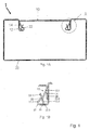
- Fig. 1 A can be seen a cable channel 1 with the lateral closure profiles 12, 22 for top earthing.
- the lower part 20 has laterally shaped Z-shaped profiled pockets 22 for receiving two-sided Z-shaped legs 12 of the upper part 10.
- the legs 12 of the upper part 10 are grounding lugs 14 bent out by free punch, which press on the side wall profile of the pocket 22 of the lower part 20.
- the letter A indicates the detail enlargement of the closure profile shown in FIG. 1B.
- FIG. 1B shows an enlarged detail A of the top earthing from FIG. 1A. It can be seen the individual contours of the Z-shaped profiled pocket 22 consisting of a downwardly extending side wall 22.4, an angled by about 90 ° extending web 22.3, and a Z-shaped leg profile with the two leg elements 22.1, 22.2.
- the two leg elements 22.1, 22.2 form by their Z-shaped profiling a projection 26 (see Figure 2 B).
- the leg 12 consists of a slightly inclined into the interior of the cable channel first leg portion 12.1 and an angled outwardly inclined second leg portion 12.2. Due to the skewed course of the two leg sections 12.1, 12.2, a projection 16 is formed (see FIG. 2A) which can be latched under the projection 26 of the leg profile 22.1, 22.2 of the pocket 22 for a latching connection. At the projections 16, 26, the leg 12 and the pocket 22 touch whereby a first contact region 23 for potential equalization arises.
- grounding lug 14 is formed by free cut.
- the grounding lug 14 is against the Sidewall profile 22.4 of the pocket 22 is pressed. This creates a second contact region 24.
- a third contact region 25 is formed by the contact of the second leg portion 12.2 of the leg 12 with the web 22.3 of the pocket 22nd
- Fig. 2 A can be seen the leg 12 of the upper part 10 with its two leg portions 12.1, 12.2.
- the first leg section 12. 1 is inclined slightly into the interior of the cable channel 1.
- the second leg portion 12.2 is angled outwards.
- Both leg sections 12.1, 12.2 form a Z-profile with the projection 16.
- the contours, which are preferably kept free of paint are indicated by a dashed line.
- the entire marked area is kept free of lacquer.
- Fig. 2 B one recognizes the pocket 22 of the lower part 20. It can be seen the downwardly shaped side wall profile 22.4, the angled extending web 22.3 and the two leg members 22.1, 22.2. By the Z-shaped configuration of the leg members 22.1, 22.2, the projection 26 is formed. The projections 16, 26 cause the latching connection and electrical contact.
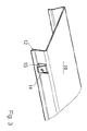
- FIG. 3 shows the upper part 10 with the two lateral, bevelled legs 12. It can be seen that produced by a three-sided cutout and outwardly by about 30 ° protruding grounding lug 14. In the area of the free cut creates an opening 19th
- Fig. 4 A can be seen a cable channel 1 in which the upper part 10 and the lower part 20 are separated. It can be seen the lateral closure contours with the profiled legs 12, the grounding lugs 14 and the pockets 22 with the Z-shaped profiled leg profile (22.1, 22.2).
Landscapes
- Engineering & Computer Science (AREA)
- Architecture (AREA)
- Civil Engineering (AREA)
- Structural Engineering (AREA)
- Details Of Indoor Wiring (AREA)
- Waveguide Aerials (AREA)
- Suspension Of Electric Lines Or Cables (AREA)
Abstract
Description
- Die vorliegende Erfindung betrifft eine Oberteilerdung für einen Kabelkanal gemäß dem Oberbegriff des Anspruchs 1.
- Leitungsführungskanäle sind weltweit in großen Stückzahlen seit langer Zeit in Gebrauch.
- Bei Kabelkanälen aus Metall ist es erforderlich, Potentialausgleichsverbindungen zwischen dem Deckel und dem Unterteil sicherzustellen, um eine Erdung zu gewährleisten. Dies wird beispielsweise mittels Erdungsfahnen erreicht, die aus dem Blech der Kabelkanäle selbst hergestellt sind. Hierzu wird ein dreiseitiger Freischnitt ausgeführt und die so gebildete Fahne soweit abgebogen, dass ein Steckverbinder aufgeschoben werden kann. Dadurch ist der Deckel mit dem Unterteil elektrisch verbunden. Solche Erdungsfahnen sind beispielsweise in der
DE 40 36 249 A oderDE 92 13 231.6 U1 beschrieben. Die Verwendung von Steckverbindung sind allerdings nachteilig, da der Montageaufwand groß ist und das Aufsetzen der Steckverbinder auf die Erdungsfahnen bei der Montage oft vergessen wird. - Kabelkanäle sind üblicherweise lackiert oder pulverbeschichtet, um den Anforderungen des Korrosionsschutzes und der Ästhetik zu genügen. Die Beschichtung erfolgt mit einem Pulver, das zunächst elektrostatisch aufgetragen und dann eingebrannt wird. Zur Erdung sind daher umfangreichere Maßnahmen erforderlich, um den Potentialausgleich zwischen Oberteil und Unterteil sicherzustellen. Die Erdungsanschlüsse werden meist gesondert hergestellt und werksseitig mit den Kanälen verbunden. Auch müssen die Potentialausgleichsleitungen getrennt hergestellt und auf der Baustelle montiert werden.
-
EP 0 518 404 schlägt daher vor, am Oberteil einen Streifen anzubringen, der in das Innere der U-Form des Deckels hin verläuft und mit wenigstens einem vorspringenden Abschnitt versehen ist, welcher eine scharfe Kante aufweist. Die Kante ist so ausgeformt, dass sie an der Seitenwand der entsprechenden Nut des Unterteils einen Kratzkontakt erzeugt. Durch das Einkratzen kann eine elektrische Kontaktierung selbst bei lackierten oder pulverbeschichteten Kabelkanalelementen erfolgen. Ein ähnliches Prinzip, allerdings mit nach Innen greifenden Lappen, schlägt auchDE 299 09 364 U1 vor. - Diese Lösungen haben jedoch den Nachteil, dass die scharfe Kante des Abschnittes oder Lappens tief genug durch den Lack in das Metall greifen muss, um die erforderlichen Leitwerte zu erreichen. Dies ist insbesondere bei verschiedenen Lackstärken und -zusammensetzungen nicht immer ganz einfach. Außerdem besteht bei den scharfen Kanten eine Verletzungsgefahr für den Installateur.
- In
DE 200 10 253 U1 wird eine Erdungsmöglichkeit beschrieben, bei der bestimmte Flächenbereiche des Deckels und des Unterteils frei von Beschichtungsmaterial sind, so dass eine Kontaktierung und Erdung über die nicht lackierten Stellen erfolgen kann. Diese Konstruktion hat allerdings den Nachteil, dass bei der leichtesten Verformung des Unterteils oder Deckels die Gefahr besteht, dass die Kontaktflächen nicht mehr schlüssig aufeinanderliegen und kein ausreichender Potentialausgleich stattfinden kann. - Es ist daher Aufgabe der vorliegenden Erfindung eine Oberteilerdung für einen lackierten Kabelkanal aus Metall vorzuschlagen, bei dem bereits beim Aufsetzen des Oberteils auf das Unterteil eine sichere Erdungsfunktion des Kabelkanals gewährleistet wird, ohne dass Hilfsteile wie Leitungen und Steckverbinder oder Installationsarbeiten erforderlich sind.
- Diese Aufgabe wird gelöst durch eine Oberteilerdung für einen Kabelkanal aus Metall mit Merkmalen des Anspruchs 1.
- Die erfindungsgemäße Oberteilerdung besteht aus Erdungskontakten, die durch seitlich ausgebildete Verschlussprofile des Unterteils bzw. Oberteils eines Kabelkanals gebildet werden.
- Das Verschlussprofil am Unterteil besteht aus zwei seitlichen U-förmig ausgebildeten Taschen, in denen die seitlich ausgeformte Schenkel des Oberteils einrastbar sind. Die Taschen bestehen aus einem Seitenwandprofil, einem Steg und einem Z-förmig profilierten Schenkel. Der Steg bildet den Taschenboden und dient als Kontakt- und Auflagefläche für die Schenkel des Oberteils.
- Die Schenkel des Oberteils besitzen ebenfalls eine Z-förmige Ausgestaltung und zumindest eine um etwa 30° aus dem Blech herausgebogene Erdungsfahne. Die Erdungsfahne wird vorzugsweise aus einem etwa dreiseitigen Freischnitt gebildet.
- Beim Einsetzen des Oberteils entsteht über verschiedene Kontaktbereiche eine elektrische Kontaktierung, so dass ein elektrischer Potentialausgleich zwischen dem Oberteil und dem Unterteil möglich ist.
- Der erste Kontaktbereich wird über die aus dem Schenkel des Oberteils nach außen herausgebogene Erdungsfahne gebildet, die gegen das Seitenwandprofil der Tasche des Unterteils drückt. Der zweite Kontaktbereich entsteht über Vorsprünge der Z-förmigen Profilierung der Taschen und Schenkel. Der dritte Kontaktbereich befindet sich an der Schenkelspitze des Oberteils und dem Steg des Unterteils.
- Die einzelnen Kontaktbereiche sind frei von Beschichtungsmaterial, insbesondere einer Pulverbeschichtung wie sie normalerweise zur Lackierung von Kabelkanälen eingesetzt wird. Eine solche Pulverbeschichtung verhindert die elektrische Kontaktierung zwischen den zu verbindenden Metallelementen, so dass keine ausreichender Potentialausgleich erfolgen kann. In den Kontaktbereichen ist daher kein Beschichtungsmaterial aufgetragen. Vorzugsweise sind der gesamte Schenkelbereich des Oberteils und Taschenbereich des Unterteils nicht beschichtet. Der Kabelkanal selbst besteht aus Stahlblech oder Aluminium.
- In einer weiteren Ausführungsform ist die vorspringende Erdungsfahne mit einer scharfen Kante versehen, so dass sie in das Material des Oberteils hineinschneidet.
- Die beidseitigen Schenkel des Deckels und die Schenkelprofile der Taschen sind Z-förmig profiliert, so dass beim Einsetzen des Oberteils in das Unterteil eine Rastverbindung erzeugt wird. Hierdurch werden das Unterteil und das Oberteil seitlich zusammengepresst. Das Oberteil schließt schlüssig mit den Oberflächenprofilen des Unterteils ab.
- Durch den erfindungsgemäßen Aufbau der Oberteilerdung aus Verschlussprofilen des Unterteils und Oberteils werden hervorragende Leitwerte für den Potentialausgleich erreicht. Dadurch, dass sich die Erdungsfahne zwischen Schenkel des Oberteils und Seitenwandprofil des Unterteils befindet, ist sie nach außen hin geschützt, so dass der Installateur keinerlei Verletzungsgefahr ausgesetzt ist. Ferner sind keine Hilfsmittel oder Installationsarbeiten durch einen Elektroinstallateur notwendig, welche in der Praxis oftmals vergessen werden und damit ein großes Sicherheitsrisiko darstellen können.
- Anhand der Zeichnungen soll die Erfindung in Form von Ausführungsbeispielen näher erläutert werden. Es zeigen jeweils rein schematisch
- Fig. 1
- ein Profil eines Kabelkanals mit seitlichen Verschlussprofilen zur Oberteilerdung (Fig. 1 A) sowie eine Ausschnittsvergrößerung der Verschlussprofile (Fig. 1 B).
- Fig. 2
- einen Schenkel eines Oberteils mit Erdungsfahne (Fig. 2 A) und eine Ausgestaltung der Tasche eines Unterteils (Fig. 2 B).
- Fig. 3
- ein Oberteil mit einer durch Freischnitt nach außen herausgebogenen Erdungsfahne.
- Fig. 4
- einen Kabelkanal mit Oberteil und Unterteil in zwei Montagestufen (Fig. 4A und 4B).
- In Fig. 1 A erkennt man einen Kabelkanal 1 mit den seitlichen Verschlussprofilen 12, 22 zur Oberteilerdung. Der Kabelkanal 1 besteht aus einem Unterteil 20 und einem darin eingerasteten Oberteil 10. Das Unterteil 20 besitzt seitlich ausgeformte Z-förmig profilierte Taschen 22 zur Aufnahme von zweiseitig Z-förmig ausgestaltete Schenkel 12 des Oberteils 10. Aus den Schenkeln 12 des Oberteils 10 sind Erdungsfahnen 14 durch Freischnitt herausgebogen, welche an das Seitenwandprofil der Tasche 22 des Unterteils 20 drücken. Der Buchstabe A kennzeichnet die in Fig. 1 B gezeigte Ausschnittsvergrößerung des Verschlussprofils.
- In Fig. 1 B ist eine Ausschnittsvergrößerung A der Oberteilerdung aus Fig. 1 A dargestellt. Man erkennt die einzelnen Konturen der Z-förmig profilierten Tasche 22 bestehend aus einem nach unten verlaufenden Seitenwandprofil 22.4, einem dazu um etwa 90° verwinkelt verlaufenden Steg 22.3, und einem Z-förmig ausgestalteten Schenkelprofil mit den beiden Schenkelelementen 22.1, 22.2. Die beiden Schenkelelemente 22.1, 22.2 bilden durch ihre Z-förmige Profilierung einen Vorsprung 26 (siehe Figur 2 B).
- Der Schenkel 12 besteht aus einem leicht in das Innere des Kabelkanals geneigten ersten Schenkelabschnitt 12.1 und einem dazu verwinkelt nach außen geneigten zweiten Schenkelabschnitt 12.2. Durch den verwinkelten Verlauf der beiden Schenkelabschnitte 12.1, 12.2 entsteht ein Vorsprung 16 (siehe Figur 2A), der für eine Rastverbindung unter den Vorsprung 26 des Schenkelprofils 22.1, 22.2 der Tasche 22 einrastbar ist. An den Vorsprüngen 16, 26 berühren sich der Schenkel 12 und die Tasche 22 wodurch ein erster Kontaktbereich 23 für einen Potentialausgleich entsteht.
- An dem ersten Schenkelabschnitt 12.1 des Schenkels 12 ist durch Freischnitt eine Erdungsfahne 14 ausgeformt. Die Erdungsfahne 14 wird gegen das Seitenwandprofil 22.4 der Tasche 22 gedrückt. Dadurch entsteht ein zweiter Kontaktbereich 24.
- Ein dritter Kontaktbereich 25 entsteht durch die Berührung des zweiten Schenkelabschnittes 12.2 des Schenkels 12 mit dem Steg 22.3 der Tasche 22.
- In Fig. 2 A erkennt man den Schenkel 12 des Oberteils 10 mit seinen beiden Schenkelabschnitten 12.1, 12.2. Der erste Schenkelabschnitt 12.1 ist leicht in das Innere des Kabelkanals 1 geneigt. Der zweite Schenkelabschnitt 12.2 verläuft verwinkelt nach außen. Beide Schenkelabschnitte 12.1, 12.2 bilden ein Z-Profil mit dem Vorsprung 16. Weiter erkennt man die Erdungsfahne 14. Die Konturen, die bevorzugt lackfrei gehalten werden sind anhand einer gestrichelten Markierung angedeutet. Vorzugsweise wird der gesamte markierte Bereich lackfrei gehalten.
- In Fig. 2 B erkennt man die Tasche 22 des Unterteils 20. Man erkennt das nach unten ausgeformte Seitenwandprofil 22.4, den verwinkelt verlaufenden Steg 22.3 und die beiden Schenkelelemente 22.1, 22.2. Durch die Z-förmige Ausgestaltung der Schenkelelemente 22.1, 22.2 entsteht der Vorsprung 26. Die Vorsprünge 16, 26 bewirken die Rastverbindung und elektrische Kontaktierung.
- In Fig. 3 erkennt man das Oberteil 10 mit den beiden seitlichen, abgeschrägten Schenkel 12. Man erkennt die durch einen dreiseitigen Freischnitt hergestellte und nach außen um etwa 30° herausstehende Erdungsfahne 14. Im Bereich des Freischnittes entsteht eine Öffnung 19.
- In Fig. 4 A erkennt man einen Kabelkanal 1 bei dem das Oberteil 10 und das Unterteil 20 getrennt sind. Man erkennt die seitlichen Verschlusskonturen mit den profilierten Schenkeln 12, den Erdungsfahnen 14 sowie die Taschen 22 mit dem Z-förmig profilierten Schenkelprofil (22.1, 22.2).
- In Fig. 4 B ist das Schenkelprofil des Oberteils 10 auf die Verschlusskontur des Unterteils 20 aufgesetzt, aber noch nicht eingerastet. Zum Einrasten wird das Oberteil 10 vollständig von oben in die Taschen 22 des Unterteils 20 gedrückt.
- Dadurch verrasten die Vorsprünge 16 des Schenkels 12 mit den Vorsprüngen 26 des Schenkelprofils (22.1, 22.2) der Tasche 22. Über die einzelnen lackfrei gehaltenen Kontaktbereiche ist ein elektrischer Potentialausgleich zwischen Oberteil und Unterteil des Kabelkanals möglich.
Claims (10)
- Oberteilerdung für einen Kabelkanal, umfassend:- seitliche aus einem U-förmigen Unterteil (20) eines metallenen Kabelkanals (1) ausgebildete Taschen (22) mit U-Profil bestehend aus einem Seitenwandprofil (22.4), einem verwinkelt dazu verlaufenden Steg (22.3) und Z-förmig profilierten Schenkelabschnitten (22.1, 22.2), die einen Vorsprung (26) bilden,- seitliche aus einem U-förmigen Oberteil (10) eines metallenen Kabelkanals (1) verwinkelte Schenkel (12), wobei die Schenkel (12) aus einem ersten und zweiten Schenkelabschnitt (12.1, 12.2) bestehen, die Z-förmig profiliert sind, so dass ein Vorsprung (16) entsteht, wobei- das Oberteil (10) und/oder das Unterteil (20) des Kabelkanals (1) mit einem Beschichtungsmaterial, insbesondere einer Pulverbeschichtung versehen sein können,- eine aus dem Schenkel (12) heraustretende nach außen gerichtete Erdungsfahne (14),gekennzeichnet durch die Merkmale:- der Steg (22.3) der Tasche (22) bildet mit dem zweiten Schenkelabschnitt (12.2) des Schenkels (12) einen ersten Kontaktbereich (23),- die Erdungsfahne (14) bildet mit dem Seitenwandprofil (22.4) der Tasche (22) einen zweiten Kontaktbereich (24),- die Vorsprünge (16, 26) des Schenkels (12) bzw. der Tasche (22) sind ineinander einrastbar und bilden einen dritten Kontaktbereich (25),- zumindest einer der drei Kontaktbereiche (23, 24, 25) ist frei von Beschichtungsmaterial.
- Oberteilerdung nach Anspruch 1, gekennzeichnet durch die Merkmale:- die Erdungsfahne (14) ist aus dem ersten Schenkelabschnitt (12.1) dreiseitig freigeschnitten und- mit einem Winkel von etwa 30° nach außen gebogen.
- Oberteilerdung nach einem der Ansprüche 1 oder 2, gekennzeichnet durch das Merkmal:- alle drei Kontaktbereiche (23, 24, 25) sind frei von Beschichtungsmaterial.
- Oberteilerdung nach einem der Ansprüche 1 bis 3, gekennzeichnet durch das Merkmal:- der Schenkel (12) und die Tasche (22) sind vollständig frei von Beschichtungsmaterial.
- Kabelkanal mit Oberteilerdung, umfassend:- ein Unterteil (20) mit U-Profil aus Metall und seitlich ausgebildeten U-förmigen Taschen (22) bestehend aus einem Seitenwandprofil (22.4), einem verwinkelt dazu verlaufenden Steg (22.3) und Z-förmig profilierten Schenkelabschnitten (22.1, 22.2), die einen Vorsprung (26) bilden,- ein Oberteil (10) mit U-Profil aus Metall und seitlich verwinkelten Schenkeln (12), wobei die Schenkel (12) aus einem ersten und zweiten Schenkelabschnitt (12.1, 12.2) bestehen und Z-förmig profiliert sind, so dass ein Vorsprung (16) entsteht, wobei- das Oberteil (10) und/oder das Unterteil (20) mit einem Beschichtungsmaterial, insbesondere einer Pulverbeschichtung versehen sein können,- eine aus dem Schenkel (12) heraustretende nach außen weisende Erdungsfahne (14),gekennzeichnet durch die Merkmale:- der Steg (22.3) der Tasche (22) bildet mit dem zweiten Schenkelabschnitt (12.2) des Schenkels (12) einen ersten Kontaktbereich (23),- die Erdungsfahne (14) bildet mit dem Seitenwandprofil (22.4) der Tasche (22) einen zweiten Kontaktbereich (24),- die Vorsprünge (16, 26) des Schenkels (12) und der Tasche (22) sind ineinander einrastbar und bilden einen dritten Kontaktbereich (25),- zumindest einer der Kontaktbereiche (23, 24, 25) ist frei von Beschichtungsmaterial.
- Kabelkanal nach Anspruch 5, gekennzeichnet durch die Merkmale:- die Erdungsfahne (14) ist aus dem ersten Schenkelabschnitt (12.1) dreiseitig freigeschnitten und- mit einem Winkel von etwa 30° nach außen gebogen.
- Kabelkanal nach Anspruch 5 oder 6, gekennzeichnet durch das Merkmal:- an dem Freischnitt der Erdungsfahne (14) befindet sich eine Öffnung (19).
- Kabelkanal nach einem der Ansprüche 5 bis 7, gekennzeichnet durch das Merkmal:- das Unterteil (20) und das Oberteil (10) des Kabelkanals (1) bestehen aus Aluminium oder Stahlblech.
- Kabelkanal nach einem der Ansprüche 5 bis 8, gekennzeichnet durch das Merkmal:- die Erdungsfahnen (14) sind in unregelmäßigen Abständen am Oberteil (10) angeordnet.
- Kabelkanal nach einem der Ansprüche 5 bis 9, gekennzeichnet durch das Merkmal:- die Oberteilerdung für das Oberteil (10) und Unterteil (20) umfasst die Merkmale nach einem der Ansprüche 1 bis 4.
Priority Applications (1)
| Application Number | Priority Date | Filing Date | Title |
|---|---|---|---|
| PL07006936T PL1848078T3 (pl) | 2006-04-21 | 2007-04-03 | Uziemienie części górnej kanału kablowego |
Applications Claiming Priority (1)
| Application Number | Priority Date | Filing Date | Title |
|---|---|---|---|
| DE202006006418U DE202006006418U1 (de) | 2006-04-21 | 2006-04-21 | Oberteilerdung für einen Kabelkanal |
Publications (3)
| Publication Number | Publication Date |
|---|---|
| EP1848078A2 true EP1848078A2 (de) | 2007-10-24 |
| EP1848078A3 EP1848078A3 (de) | 2009-08-19 |
| EP1848078B1 EP1848078B1 (de) | 2011-12-21 |
Family
ID=38326859
Family Applications (1)
| Application Number | Title | Priority Date | Filing Date |
|---|---|---|---|
| EP07006936A Not-in-force EP1848078B1 (de) | 2006-04-21 | 2007-04-03 | Oberteilerdung für einen Kabelkanal |
Country Status (5)
| Country | Link |
|---|---|
| EP (1) | EP1848078B1 (de) |
| AT (1) | ATE538520T1 (de) |
| DE (1) | DE202006006418U1 (de) |
| DK (1) | DK1848078T3 (de) |
| PL (1) | PL1848078T3 (de) |
Families Citing this family (3)
| Publication number | Priority date | Publication date | Assignee | Title |
|---|---|---|---|---|
| DE102008060808B4 (de) | 2008-12-01 | 2011-03-03 | Obo Bettermann Gmbh & Co. Kg | Bodeneinbaukassette für elektrische Installationsgeräte |
| DE102011016544A1 (de) | 2011-04-08 | 2012-10-11 | Tehalit Gmbh | Verfahren und Leitungsführungskanal zur Sicherstellung eines Potentialausgleichs |
| DE202011103720U1 (de) * | 2011-07-27 | 2012-11-15 | Tehalit Gmbh | Geräteträger mit Schnappverschluss für die Montage eines Elektroinstallationsgerätes an einen Leitungsführungskanal |
Citations (6)
| Publication number | Priority date | Publication date | Assignee | Title |
|---|---|---|---|---|
| DE4036249A1 (de) | 1990-11-14 | 1992-05-21 | Kleinhuis Hermann Gmbh | Aus einem metallischen werkstoff, wie stahlblech, bestehender kanal zur unterbringung von elektrischen installationseinrichtungen |
| DE9213231U1 (de) | 1992-10-01 | 1992-12-10 | Tehalit GmbH, 6751 Heltersberg | Deckel für Kabelkanäle |
| EP0518404A1 (de) | 1991-06-12 | 1992-12-16 | Van Geel Systems B.V. | Deckel für eine Wandrinne |
| DE20010253U1 (de) | 2000-01-12 | 2000-08-24 | OBO Bettermann GmbH & Co. KG, 58710 Menden | Kabelkanal |
| DE29909364U1 (de) | 1999-05-29 | 2000-10-12 | Tehalit GmbH, 67716 Heltersberg | Leitungsführungskanal aus Stahlblech |
| US20020050374A1 (en) | 2000-06-05 | 2002-05-02 | Charles Vander Velde | Wiring duct system hinge arrangement |
-
2006
- 2006-04-21 DE DE202006006418U patent/DE202006006418U1/de not_active Expired - Lifetime
-
2007
- 2007-04-03 PL PL07006936T patent/PL1848078T3/pl unknown
- 2007-04-03 AT AT07006936T patent/ATE538520T1/de active
- 2007-04-03 DK DK07006936.4T patent/DK1848078T3/da active
- 2007-04-03 EP EP07006936A patent/EP1848078B1/de not_active Not-in-force
Patent Citations (6)
| Publication number | Priority date | Publication date | Assignee | Title |
|---|---|---|---|---|
| DE4036249A1 (de) | 1990-11-14 | 1992-05-21 | Kleinhuis Hermann Gmbh | Aus einem metallischen werkstoff, wie stahlblech, bestehender kanal zur unterbringung von elektrischen installationseinrichtungen |
| EP0518404A1 (de) | 1991-06-12 | 1992-12-16 | Van Geel Systems B.V. | Deckel für eine Wandrinne |
| DE9213231U1 (de) | 1992-10-01 | 1992-12-10 | Tehalit GmbH, 6751 Heltersberg | Deckel für Kabelkanäle |
| DE29909364U1 (de) | 1999-05-29 | 2000-10-12 | Tehalit GmbH, 67716 Heltersberg | Leitungsführungskanal aus Stahlblech |
| DE20010253U1 (de) | 2000-01-12 | 2000-08-24 | OBO Bettermann GmbH & Co. KG, 58710 Menden | Kabelkanal |
| US20020050374A1 (en) | 2000-06-05 | 2002-05-02 | Charles Vander Velde | Wiring duct system hinge arrangement |
Also Published As
| Publication number | Publication date |
|---|---|
| EP1848078A3 (de) | 2009-08-19 |
| DK1848078T3 (da) | 2012-03-19 |
| PL1848078T3 (pl) | 2012-05-31 |
| EP1848078B1 (de) | 2011-12-21 |
| ATE538520T1 (de) | 2012-01-15 |
| DE202006006418U1 (de) | 2007-08-30 |
Similar Documents
| Publication | Publication Date | Title |
|---|---|---|
| EP2853981B1 (de) | Gehäuse für elektrische Geräte | |
| DE8437046U1 (de) | Verschlußdeckel aus Kunststoff | |
| EP3136525B1 (de) | Kabelkanal und verfahren zur herstellung eines begehbaren kabelkanaldeckels | |
| DE4311246C1 (de) | Gehäuse für elektronische Geräte | |
| DE102016117442A1 (de) | Batteriegehäuse für eine Traktionsbatterie | |
| EP1848078B1 (de) | Oberteilerdung für einen Kabelkanal | |
| EP0634550B1 (de) | Vorreiberverschluss | |
| EP0025472B1 (de) | Schaltschranktürverschluss-Befestigungsmutter zur Befestigung von aus Metall bestehenden Verschlüssen für Schaltschranktüren | |
| EP2012390B1 (de) | Erdungsklammer zum Potentialausgleich von Leitungsführungskanälen | |
| EP3963163B1 (de) | Verschliessvorrichtung | |
| DE29620839U1 (de) | Vorrichtung zum Befestigen eines Einbaugeräts in Form einer Einbauspüle o.dgl. in einer Arbeitsplatte | |
| EP0753917A1 (de) | Elektroinstallationskanal | |
| EP3264533B1 (de) | Lochscheibe sowie deren verwendung bei miteinander verbundenen stromschienen unterschiedlicher materialien | |
| DE202005015128U1 (de) | Flächige Einrichtung zur Umwandlung von Sonnenenergie in eine andere Energieform | |
| DE29903182U1 (de) | Kastenförmige Schließplatte | |
| DE102021110399B3 (de) | Aus Metall hergestellte Kabelrinnenkomponente, insbesondere Kabelrinne oder Kabelrinnendeckel | |
| EP3617042B1 (de) | Kraftfahrzeugstrukturbauteil | |
| DE29909364U1 (de) | Leitungsführungskanal aus Stahlblech | |
| EP2541705B1 (de) | Verfahren und Leitungsführungskanal zur Sicherstellung eines Potentialausgleichs | |
| DE3001350A1 (de) | Erdungsbefestigung | |
| EP2190091B1 (de) | Träger | |
| DE19814456B4 (de) | Abgangskasten mit Sicherheitsvorrichtung | |
| EP3425289B1 (de) | Verteilerschrank | |
| DE9305233U1 (de) | Gehäuse für elektronische Geräte | |
| EP1081820A1 (de) | Vorrichtung zum Herstellen des Potentialausgleichs in Leitungsführungskanälen |
Legal Events
| Date | Code | Title | Description |
|---|---|---|---|
| PUAI | Public reference made under article 153(3) epc to a published international application that has entered the european phase |
Free format text: ORIGINAL CODE: 0009012 |
|
| AK | Designated contracting states |
Kind code of ref document: A2 Designated state(s): AT BE BG CH CY CZ DE DK EE ES FI FR GB GR HU IE IS IT LI LT LU LV MC MT NL PL PT RO SE SI SK TR |
|
| AX | Request for extension of the european patent |
Extension state: AL BA HR MK YU |
|
| PUAL | Search report despatched |
Free format text: ORIGINAL CODE: 0009013 |
|
| AK | Designated contracting states |
Kind code of ref document: A3 Designated state(s): AT BE BG CH CY CZ DE DK EE ES FI FR GB GR HU IE IS IT LI LT LU LV MC MT NL PL PT RO SE SI SK TR |
|
| AX | Request for extension of the european patent |
Extension state: AL BA HR MK RS |
|
| 17P | Request for examination filed |
Effective date: 20090926 |
|
| AKX | Designation fees paid |
Designated state(s): AT BE BG CH CY CZ DE DK EE ES FI FR GB GR HU IE IS IT LI LT LU LV MC MT NL PL PT RO SE SI SK TR |
|
| 17Q | First examination report despatched |
Effective date: 20110405 |
|
| GRAP | Despatch of communication of intention to grant a patent |
Free format text: ORIGINAL CODE: EPIDOSNIGR1 |
|
| RIC1 | Information provided on ipc code assigned before grant |
Ipc: H02G 3/04 20060101AFI20110705BHEP |
|
| GRAS | Grant fee paid |
Free format text: ORIGINAL CODE: EPIDOSNIGR3 |
|
| GRAA | (expected) grant |
Free format text: ORIGINAL CODE: 0009210 |
|
| AK | Designated contracting states |
Kind code of ref document: B1 Designated state(s): AT BE BG CH CY CZ DE DK EE ES FI FR GB GR HU IE IS IT LI LT LU LV MC MT NL PL PT RO SE SI SK TR |
|
| REG | Reference to a national code |
Ref country code: GB Ref legal event code: FG4D Free format text: NOT ENGLISH |
|
| REG | Reference to a national code |
Ref country code: CH Ref legal event code: EP |
|
| REG | Reference to a national code |
Ref country code: AT Ref legal event code: REF Ref document number: 538520 Country of ref document: AT Kind code of ref document: T Effective date: 20120115 |
|
| REG | Reference to a national code |
Ref country code: IE Ref legal event code: FG4D |
|
| REG | Reference to a national code |
Ref country code: CH Ref legal event code: NV Representative=s name: PATENTANWAELTE SCHAAD, BALASS, MENZL & PARTNER AG |
|
| REG | Reference to a national code |
Ref country code: DE Ref legal event code: R096 Ref document number: 502007008881 Country of ref document: DE Effective date: 20120308 |
|
| REG | Reference to a national code |
Ref country code: DK Ref legal event code: T3 |
|
| REG | Reference to a national code |
Ref country code: NL Ref legal event code: T3 |
|
| REG | Reference to a national code |
Ref country code: SE Ref legal event code: TRGR |
|
| PG25 | Lapsed in a contracting state [announced via postgrant information from national office to epo] |
Ref country code: LT Free format text: LAPSE BECAUSE OF FAILURE TO SUBMIT A TRANSLATION OF THE DESCRIPTION OR TO PAY THE FEE WITHIN THE PRESCRIBED TIME-LIMIT Effective date: 20111221 |
|
| LTIE | Lt: invalidation of european patent or patent extension |
Effective date: 20111221 |
|
| PG25 | Lapsed in a contracting state [announced via postgrant information from national office to epo] |
Ref country code: GR Free format text: LAPSE BECAUSE OF FAILURE TO SUBMIT A TRANSLATION OF THE DESCRIPTION OR TO PAY THE FEE WITHIN THE PRESCRIBED TIME-LIMIT Effective date: 20120322 Ref country code: LV Free format text: LAPSE BECAUSE OF FAILURE TO SUBMIT A TRANSLATION OF THE DESCRIPTION OR TO PAY THE FEE WITHIN THE PRESCRIBED TIME-LIMIT Effective date: 20111221 Ref country code: SI Free format text: LAPSE BECAUSE OF FAILURE TO SUBMIT A TRANSLATION OF THE DESCRIPTION OR TO PAY THE FEE WITHIN THE PRESCRIBED TIME-LIMIT Effective date: 20111221 |
|
| REG | Reference to a national code |
Ref country code: PL Ref legal event code: T3 |
|
| PG25 | Lapsed in a contracting state [announced via postgrant information from national office to epo] |
Ref country code: CY Free format text: LAPSE BECAUSE OF FAILURE TO SUBMIT A TRANSLATION OF THE DESCRIPTION OR TO PAY THE FEE WITHIN THE PRESCRIBED TIME-LIMIT Effective date: 20111221 |
|
| REG | Reference to a national code |
Ref country code: IE Ref legal event code: FD4D |
|
| PG25 | Lapsed in a contracting state [announced via postgrant information from national office to epo] |
Ref country code: IS Free format text: LAPSE BECAUSE OF FAILURE TO SUBMIT A TRANSLATION OF THE DESCRIPTION OR TO PAY THE FEE WITHIN THE PRESCRIBED TIME-LIMIT Effective date: 20120421 Ref country code: IE Free format text: LAPSE BECAUSE OF FAILURE TO SUBMIT A TRANSLATION OF THE DESCRIPTION OR TO PAY THE FEE WITHIN THE PRESCRIBED TIME-LIMIT Effective date: 20111221 Ref country code: EE Free format text: LAPSE BECAUSE OF FAILURE TO SUBMIT A TRANSLATION OF THE DESCRIPTION OR TO PAY THE FEE WITHIN THE PRESCRIBED TIME-LIMIT Effective date: 20111221 Ref country code: SK Free format text: LAPSE BECAUSE OF FAILURE TO SUBMIT A TRANSLATION OF THE DESCRIPTION OR TO PAY THE FEE WITHIN THE PRESCRIBED TIME-LIMIT Effective date: 20111221 Ref country code: BG Free format text: LAPSE BECAUSE OF FAILURE TO SUBMIT A TRANSLATION OF THE DESCRIPTION OR TO PAY THE FEE WITHIN THE PRESCRIBED TIME-LIMIT Effective date: 20120321 |
|
| PGFP | Annual fee paid to national office [announced via postgrant information from national office to epo] |
Ref country code: LU Payment date: 20120424 Year of fee payment: 6 Ref country code: BE Payment date: 20120424 Year of fee payment: 6 Ref country code: DK Payment date: 20120424 Year of fee payment: 6 |
|
| PG25 | Lapsed in a contracting state [announced via postgrant information from national office to epo] |
Ref country code: PT Free format text: LAPSE BECAUSE OF FAILURE TO SUBMIT A TRANSLATION OF THE DESCRIPTION OR TO PAY THE FEE WITHIN THE PRESCRIBED TIME-LIMIT Effective date: 20120423 Ref country code: RO Free format text: LAPSE BECAUSE OF FAILURE TO SUBMIT A TRANSLATION OF THE DESCRIPTION OR TO PAY THE FEE WITHIN THE PRESCRIBED TIME-LIMIT Effective date: 20111221 |
|
| PGFP | Annual fee paid to national office [announced via postgrant information from national office to epo] |
Ref country code: GB Payment date: 20120423 Year of fee payment: 6 Ref country code: SE Payment date: 20120423 Year of fee payment: 6 Ref country code: FR Payment date: 20120511 Year of fee payment: 6 |
|
| REG | Reference to a national code |
Ref country code: DE Ref legal event code: R082 Ref document number: 502007008881 Country of ref document: DE |
|
| PLBE | No opposition filed within time limit |
Free format text: ORIGINAL CODE: 0009261 |
|
| STAA | Information on the status of an ep patent application or granted ep patent |
Free format text: STATUS: NO OPPOSITION FILED WITHIN TIME LIMIT |
|
| 26N | No opposition filed |
Effective date: 20120924 |
|
| PG25 | Lapsed in a contracting state [announced via postgrant information from national office to epo] |
Ref country code: MC Free format text: LAPSE BECAUSE OF NON-PAYMENT OF DUE FEES Effective date: 20120430 Ref country code: IT Free format text: LAPSE BECAUSE OF FAILURE TO SUBMIT A TRANSLATION OF THE DESCRIPTION OR TO PAY THE FEE WITHIN THE PRESCRIBED TIME-LIMIT Effective date: 20111221 |
|
| REG | Reference to a national code |
Ref country code: DE Ref legal event code: R097 Ref document number: 502007008881 Country of ref document: DE Effective date: 20120924 |
|
| PGFP | Annual fee paid to national office [announced via postgrant information from national office to epo] |
Ref country code: AT Payment date: 20120420 Year of fee payment: 6 |
|
| PG25 | Lapsed in a contracting state [announced via postgrant information from national office to epo] |
Ref country code: ES Free format text: LAPSE BECAUSE OF FAILURE TO SUBMIT A TRANSLATION OF THE DESCRIPTION OR TO PAY THE FEE WITHIN THE PRESCRIBED TIME-LIMIT Effective date: 20120401 |
|
| PG25 | Lapsed in a contracting state [announced via postgrant information from national office to epo] |
Ref country code: FI Free format text: LAPSE BECAUSE OF FAILURE TO SUBMIT A TRANSLATION OF THE DESCRIPTION OR TO PAY THE FEE WITHIN THE PRESCRIBED TIME-LIMIT Effective date: 20111221 |
|
| PG25 | Lapsed in a contracting state [announced via postgrant information from national office to epo] |
Ref country code: MT Free format text: LAPSE BECAUSE OF FAILURE TO SUBMIT A TRANSLATION OF THE DESCRIPTION OR TO PAY THE FEE WITHIN THE PRESCRIBED TIME-LIMIT Effective date: 20111221 |
|
| BERE | Be: lapsed |
Owner name: TEHALIT G.M.B.H. Effective date: 20130430 |
|
| PG25 | Lapsed in a contracting state [announced via postgrant information from national office to epo] |
Ref country code: CZ Free format text: LAPSE BECAUSE OF NON-PAYMENT OF DUE FEES Effective date: 20130403 |
|
| REG | Reference to a national code |
Ref country code: SE Ref legal event code: EUG |
|
| REG | Reference to a national code |
Ref country code: DK Ref legal event code: EBP Effective date: 20130430 |
|
| REG | Reference to a national code |
Ref country code: AT Ref legal event code: MM01 Ref document number: 538520 Country of ref document: AT Kind code of ref document: T Effective date: 20130430 |
|
| GBPC | Gb: european patent ceased through non-payment of renewal fee |
Effective date: 20130403 |
|
| PG25 | Lapsed in a contracting state [announced via postgrant information from national office to epo] |
Ref country code: AT Free format text: LAPSE BECAUSE OF NON-PAYMENT OF DUE FEES Effective date: 20130430 Ref country code: GB Free format text: LAPSE BECAUSE OF NON-PAYMENT OF DUE FEES Effective date: 20130403 Ref country code: SE Free format text: LAPSE BECAUSE OF NON-PAYMENT OF DUE FEES Effective date: 20130404 Ref country code: BE Free format text: LAPSE BECAUSE OF NON-PAYMENT OF DUE FEES Effective date: 20130430 |
|
| REG | Reference to a national code |
Ref country code: FR Ref legal event code: ST Effective date: 20131231 |
|
| PG25 | Lapsed in a contracting state [announced via postgrant information from national office to epo] |
Ref country code: FR Free format text: LAPSE BECAUSE OF NON-PAYMENT OF DUE FEES Effective date: 20130430 |
|
| PG25 | Lapsed in a contracting state [announced via postgrant information from national office to epo] |
Ref country code: TR Free format text: LAPSE BECAUSE OF FAILURE TO SUBMIT A TRANSLATION OF THE DESCRIPTION OR TO PAY THE FEE WITHIN THE PRESCRIBED TIME-LIMIT Effective date: 20111221 Ref country code: DK Free format text: LAPSE BECAUSE OF NON-PAYMENT OF DUE FEES Effective date: 20130430 |
|
| PG25 | Lapsed in a contracting state [announced via postgrant information from national office to epo] |
Ref country code: HU Free format text: LAPSE BECAUSE OF FAILURE TO SUBMIT A TRANSLATION OF THE DESCRIPTION OR TO PAY THE FEE WITHIN THE PRESCRIBED TIME-LIMIT Effective date: 20070403 |
|
| REG | Reference to a national code |
Ref country code: PL Ref legal event code: LAPE |
|
| PG25 | Lapsed in a contracting state [announced via postgrant information from national office to epo] |
Ref country code: PL Free format text: LAPSE BECAUSE OF NON-PAYMENT OF DUE FEES Effective date: 20130403 |
|
| PG25 | Lapsed in a contracting state [announced via postgrant information from national office to epo] |
Ref country code: LU Free format text: LAPSE BECAUSE OF NON-PAYMENT OF DUE FEES Effective date: 20130403 |
|
| PGFP | Annual fee paid to national office [announced via postgrant information from national office to epo] |
Ref country code: NL Payment date: 20170426 Year of fee payment: 11 |
|
| PGFP | Annual fee paid to national office [announced via postgrant information from national office to epo] |
Ref country code: DE Payment date: 20170427 Year of fee payment: 11 Ref country code: CH Payment date: 20170427 Year of fee payment: 11 |
|
| REG | Reference to a national code |
Ref country code: DE Ref legal event code: R119 Ref document number: 502007008881 Country of ref document: DE |
|
| REG | Reference to a national code |
Ref country code: CH Ref legal event code: PL |
|
| REG | Reference to a national code |
Ref country code: NL Ref legal event code: MM Effective date: 20180501 |
|
| PG25 | Lapsed in a contracting state [announced via postgrant information from national office to epo] |
Ref country code: NL Free format text: LAPSE BECAUSE OF NON-PAYMENT OF DUE FEES Effective date: 20180501 Ref country code: DE Free format text: LAPSE BECAUSE OF NON-PAYMENT OF DUE FEES Effective date: 20181101 |
|
| PG25 | Lapsed in a contracting state [announced via postgrant information from national office to epo] |
Ref country code: CH Free format text: LAPSE BECAUSE OF NON-PAYMENT OF DUE FEES Effective date: 20180430 Ref country code: LI Free format text: LAPSE BECAUSE OF NON-PAYMENT OF DUE FEES Effective date: 20180430 |
|
| P01 | Opt-out of the competence of the unified patent court (upc) registered |
Effective date: 20230606 |