EP1848085A2 - Modulares bidirektionales Bussystem um Energie zwischen Module auszutauschen - Google Patents
Modulares bidirektionales Bussystem um Energie zwischen Module auszutauschen Download PDFInfo
- Publication number
- EP1848085A2 EP1848085A2 EP07106558A EP07106558A EP1848085A2 EP 1848085 A2 EP1848085 A2 EP 1848085A2 EP 07106558 A EP07106558 A EP 07106558A EP 07106558 A EP07106558 A EP 07106558A EP 1848085 A2 EP1848085 A2 EP 1848085A2
- Authority
- EP
- European Patent Office
- Prior art keywords
- bus
- type
- module
- energy
- voltage
- Prior art date
- Legal status (The legal status is an assumption and is not a legal conclusion. Google has not performed a legal analysis and makes no representation as to the accuracy of the status listed.)
- Withdrawn
Links
Images

Classifications
-
- H—ELECTRICITY
- H02—GENERATION; CONVERSION OR DISTRIBUTION OF ELECTRIC POWER
- H02M—APPARATUS FOR CONVERSION BETWEEN AC AND AC, BETWEEN AC AND DC, OR BETWEEN DC AND DC, AND FOR USE WITH MAINS OR SIMILAR POWER SUPPLY SYSTEMS; CONVERSION OF DC OR AC INPUT POWER INTO SURGE OUTPUT POWER; CONTROL OR REGULATION THEREOF
- H02M3/00—Conversion of DC power input into DC power output
- H02M3/22—Conversion of DC power input into DC power output with intermediate conversion into AC
- H02M3/24—Conversion of DC power input into DC power output with intermediate conversion into AC by static converters
- H02M3/28—Conversion of DC power input into DC power output with intermediate conversion into AC by static converters using discharge tubes with control electrode or semiconductor devices with control electrode to produce the intermediate AC
-
- H—ELECTRICITY
- H02—GENERATION; CONVERSION OR DISTRIBUTION OF ELECTRIC POWER
- H02J—ELECTRIC POWER NETWORKS; CIRCUIT ARRANGEMENTS OR SYSTEMS FOR SUPPLYING OR DISTRIBUTING ELECTRIC POWER; SYSTEMS FOR STORING ELECTRIC ENERGY
- H02J3/00—Circuit arrangements for AC mains or AC distribution networks
- H02J3/38—Arrangements for feeding a single network from two or more generators or sources in parallel; Arrangements for feeding already energised networks from additional generators or sources in parallel
- H02J3/381—Dispersed generators
-
- H—ELECTRICITY
- H02—GENERATION; CONVERSION OR DISTRIBUTION OF ELECTRIC POWER
- H02J—ELECTRIC POWER NETWORKS; CIRCUIT ARRANGEMENTS OR SYSTEMS FOR SUPPLYING OR DISTRIBUTING ELECTRIC POWER; SYSTEMS FOR STORING ELECTRIC ENERGY
- H02J3/00—Circuit arrangements for AC mains or AC distribution networks
- H02J3/38—Arrangements for feeding a single network from two or more generators or sources in parallel; Arrangements for feeding already energised networks from additional generators or sources in parallel
- H02J3/46—Controlling the sharing of generated power between the generators, sources or networks
- H02J3/466—Scheduling or selectively controlling the operation of the generators or sources, e.g. connecting or disconnecting generators to meet a demand
-
- H—ELECTRICITY
- H02—GENERATION; CONVERSION OR DISTRIBUTION OF ELECTRIC POWER
- H02J—ELECTRIC POWER NETWORKS; CIRCUIT ARRANGEMENTS OR SYSTEMS FOR SUPPLYING OR DISTRIBUTING ELECTRIC POWER; SYSTEMS FOR STORING ELECTRIC ENERGY
- H02J2101/00—Supply or distribution of decentralised, dispersed or local electric power generation
- H02J2101/20—Dispersed power generation using renewable energy sources
- H02J2101/22—Solar energy
- H02J2101/24—Photovoltaics
-
- H—ELECTRICITY
- H02—GENERATION; CONVERSION OR DISTRIBUTION OF ELECTRIC POWER
- H02J—ELECTRIC POWER NETWORKS; CIRCUIT ARRANGEMENTS OR SYSTEMS FOR SUPPLYING OR DISTRIBUTING ELECTRIC POWER; SYSTEMS FOR STORING ELECTRIC ENERGY
- H02J2101/00—Supply or distribution of decentralised, dispersed or local electric power generation
- H02J2101/20—Dispersed power generation using renewable energy sources
- H02J2101/28—Wind energy
-
- H—ELECTRICITY
- H02—GENERATION; CONVERSION OR DISTRIBUTION OF ELECTRIC POWER
- H02J—ELECTRIC POWER NETWORKS; CIRCUIT ARRANGEMENTS OR SYSTEMS FOR SUPPLYING OR DISTRIBUTING ELECTRIC POWER; SYSTEMS FOR STORING ELECTRIC ENERGY
- H02J2101/00—Supply or distribution of decentralised, dispersed or local electric power generation
- H02J2101/40—Hybrid power plants, i.e. a plurality of different generation technologies being operated at one power plant
-
- Y—GENERAL TAGGING OF NEW TECHNOLOGICAL DEVELOPMENTS; GENERAL TAGGING OF CROSS-SECTIONAL TECHNOLOGIES SPANNING OVER SEVERAL SECTIONS OF THE IPC; TECHNICAL SUBJECTS COVERED BY FORMER USPC CROSS-REFERENCE ART COLLECTIONS [XRACs] AND DIGESTS
- Y02—TECHNOLOGIES OR APPLICATIONS FOR MITIGATION OR ADAPTATION AGAINST CLIMATE CHANGE
- Y02E—REDUCTION OF GREENHOUSE GAS [GHG] EMISSIONS, RELATED TO ENERGY GENERATION, TRANSMISSION OR DISTRIBUTION
- Y02E10/00—Energy generation through renewable energy sources
- Y02E10/50—Photovoltaic [PV] energy
- Y02E10/56—Power conversion systems, e.g. maximum power point trackers
-
- Y—GENERAL TAGGING OF NEW TECHNOLOGICAL DEVELOPMENTS; GENERAL TAGGING OF CROSS-SECTIONAL TECHNOLOGIES SPANNING OVER SEVERAL SECTIONS OF THE IPC; TECHNICAL SUBJECTS COVERED BY FORMER USPC CROSS-REFERENCE ART COLLECTIONS [XRACs] AND DIGESTS
- Y02—TECHNOLOGIES OR APPLICATIONS FOR MITIGATION OR ADAPTATION AGAINST CLIMATE CHANGE
- Y02P—CLIMATE CHANGE MITIGATION TECHNOLOGIES IN THE PRODUCTION OR PROCESSING OF GOODS
- Y02P80/00—Climate change mitigation technologies for sector-wide applications
- Y02P80/10—Efficient use of energy, e.g. using compressed air or pressurized fluid as energy carrier
- Y02P80/14—District level solutions, i.e. local energy networks
Definitions
- the invention relates to a system for exchanging energy.
- a stepwise shift occurs from centralized thinking to decentralized thinking, in which distributed power generation and distributed power storage play a key role.
- the exploitation of hydrogen can also be considered in the same development where small units will become available to the market to the level of the smallest user. This also holds for wind and solar energy.
- the invention contemplates providing a system which can support at least a number of the above-mentioned objects and such that the system can be built up flexibly and adjusted to the desires of a user.
- the invention relates to a modular bidirectional bus system for exchanging energy between modules, provided with at least a bus and a plurality of exchangeable modules which are detachably connected with the bus for mutually exchanging electric energy between the modules via the bus, while the system is provided with at least two different modules of the following types:
- the bus system has a modular structure, it can completely be arranged as desired. This is because the modules are detachably connected with the bus system. Because the system comprises at least two different types of modules, the system can, on the one hand, take up energy supplied from different first types or third types of apparatuses via first types of and/or third types of modules and, on the other hand, deliver this energy to different other second or third types of apparatuses via the second types and/or third types of modules. Because the system is arranged such that the modules operatively generate a predetermined voltage on the bus, the system can be used for different first types, second types and third types of apparatuses.
- the predetermined voltage is a DC voltage.
- a first type of apparatus connected with the system comprises a fuel cell delivering a DC voltage.
- the system comprises, for instance, a module of the first (or third) type arranged to draw energy from the fuel cell and to offer this energy with this DC voltage to the bus.
- the respective module is provided with a DC/DC converter.
- a second type of apparatus connected with the system comprises an AC local electricity grid of a house or a building.
- the system is at least provided with a module of the second (or third) type which is connected with the second apparatus, which second module is provided with a DC/AC converter in order to convert the DC voltage of the bus to an AC voltage for the benefit of the local electricity grid of the house or building.
- a third type of apparatus connected with the system is an apparatus for storing and delivering energy such as a supercap.
- the system is then, for instance, provided with a third type of module which is operatively connected with the third type of apparatus.
- a third type of module, in case it is coupled with a supercap, is again, to this end, provided with at least one DC/DC converter.
- the system is preferably further provided with a control device which can activate or deactivate any type of module for delivering energy via the first connection and taking up energy via a second connection or for taking up energy via the first connection and delivering energy via the second connection.
- a control device which can activate or deactivate any type of module for delivering energy via the first connection and taking up energy via a second connection or for taking up energy via the first connection and delivering energy via the second connection.
- the fuel cell generates energy
- this can be supplied to the bus via a first type of module.
- This energy can then be stored in the battery or supercap via a third type of module.
- the first type of module converts the voltage generated by the fuel cell to the predetermined voltage on the bus.
- the local AC grid then starts to use energy which is connected with the bus via a second type of module, energy will be drawn from the bus via the second type of module.
- this energy may be drawn from the fuel cell directly via the first module and/or be drawn via the third module of the supercap or battery.
- a user may, for instance, control the control device such that the energy needed is only drawn from the supercap. Also, a user may indicate that he, conversely, does not wish this and that the energy needed is drawn from the fuel cell.
- a second module of the third type can be added, which module is, on the one hand, coupled with the bus and, on the other hand, coupled with a public electricity grid.
- this module is provided with an AC/DC converter.
- the local electricity grid can draw energy from the bus via a module of the second type, which energy is delivered by the second module of the third type which is connected with the public electricity grid. In other words, energy is drawn from the public electricity grid.
- the control device brings about that energy generated by the fuel cell and supplied to the bus is supplied to the public electricity grid via the second module of the third type if, for instance, the price of electric energy per kilowatt/hour is relatively high. If the price is relatively low, the control device can bring about that the energy of the fuel cell is supplied to the supercap. This energy which is supplied to the supercap can, at any moment, be supplied to the local electricity grid via a first module of the third type and a module of the second type to meet a present energy need.
- the energy stored in the supercap is, at any moment, supplied to the public electricity grid via a first module of the third type and a second module of the third type when the price of electric energy is relatively high.
- a user can buy energy inexpensively, store it and optionally sell it at a later time.
- the modular bidirectional bus system can be added to in a simple manner and arranged according to the specific wishes of a user of the system.
- the modules are, in combination, arranged such that a predetermined voltage is operatively generated on the bus.
- a predetermined voltage is operatively generated on the bus.
- Such a system has the advantage that, in fact, the modules themselves ensure that the predetermined voltage is generated. Therefore, it is preferred that the modules themselves generate the predetermined voltage depending on supply and/or drawing of energy with a module.
- the modules are, in combination, arranged such that a voltage is operatively received on the bus which is within a predetermined voltage interval. So, in this manner, the modules themselves generate and regulate the voltage on the bus depending on the charge of the modules.
- a third type of module is seen as a special variant of a first type of module.
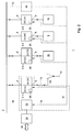
- reference numeral 1 designates a modular bidirectional bus system according to the invention.
- the modules 2.4 and 2.5 are each a first type of module.
- Each first type of module has at least one first connection 4 which is, as shown in this example, operatively electrically connected with the bus 2 for supplying energy to the bus via the first connection of the first type of module.
- Each first type of module is further provided with a second connection 6 which is operatively connected with a first type of apparatus 8,10 for drawing energy from the first types of apparatuses 8,10, respectively, via the second connection 6.
- the apparatus 8 is a solar cell and, in this example, the apparatus 10 is a windmill. It will be clear that both the solar cell 8 and the windmill 10 can generate electric energy and deliver this to the respective modules 2.4 and 2.5 which can, in turn, deliver this energy to the bus 2.
- the system is further provided with one module 2.2 which is a second type of module.
- Each second type of module such as the module 2.2, is provided with a first connection 4 which is, as shown in this example, operatively electrically connected with the bus 2 for drawing energy from the bus via the first connection 4.
- each second type of module such as the module 2.2, is provided with a second connection 6 which is operatively connected with a second type of apparatus 12 for supplying energy to the second type of apparatus 12 via the second connection 6 of the second type of module.
- the second type of apparatus 12 consists of a local AC electricity grid of a building or a house.
- the system is further provided with two modules 2.1 and 2.3 which are each a third type of module.
- Each third type of module such as the modules 2.1 and 2.3, is provided with a first connection 4 which is, as shown in this example, operatively electrically connected with the bus 2 and a second connection 6 which is operatively connected with a third type of apparatus, in this example the apparatuses 14,16, for, as desired, supplying energy to the bus via the first connection 4 of the third type of module and drawing energy from the third type of apparatus via the second connection 6 of the third type of module or drawing energy from the bus via the first connection 4 of the third type of module and supplying energy to the third type of apparatus via the second connection 6 of the third type of module.
- the apparatus 14 consists of the public electricity grid and the apparatus 16 of a supercap.
- the system is, as will be explained herein in more detail, arranged such that the modules 2.1 operatively generate a predetermined voltage on the bus.
- this is a DC voltage.
- the first module 2.1 is provided with a DC/AC and an AC/DC converter. Because the local AC electricity grid is also powered by an AC voltage, the module 2.2 is also provided with a DC/AC converter.
- the supercap 16 (this is a type of battery) is powered by a DC voltage, which is the reason why the module 2.3 is provided with at least one DC/DC converter (in this example a first DC/DC converter for charging the supercap with energy from the bus and a second DC/DC converter for supplying energy from the supercap to the bus).
- the solar panel 8 and the windmill 10 are also each powered by a DC voltage, which is the reason why each of the modules 2.4 and 2.5 is provided with a DC/DC converter.
- the system is further provided with a control device 20 which can control each first type of module (in this example the modules 2.4 and 2.5), such as activate or deactivate it for delivering energy via the first connection and drawing energy via the second connection.
- the control device 20 can also activate or deactivate each second type of module (module 2.2) for taking up energy via the first connection and delivering energy via the second connection of the second type of module.
- the control device 20 can activate or deactivate each third type of module (in this example the modules 2.1 and 2.3) for, as desired: delivering energy via the first connection and taking up energy via the second connection; or taking up energy via the first connection and delivering energy via the second connection.
- control device 20 generates control signals on a line 22 connecting the control device 20 with each of the modules 2.i for the above-mentioned activation and deactivation of the modules.
- system is further provided with a computer 24 which is connected with the control device 20. Via the line 22, further, information from each module can be supplied to the control device 20.
- Each module is further provided with a local control unit 26 which is connected with the control unit 20.
- the second type of module 2.4 converts the DC voltage to a DC voltage of about 400 volt and then, for instance, ensures that, on the bus 2, a predetermined DC voltage of, in this example, about 400 volt is generated.
- the local control unit 26 of the module 2.4 communicates to the control device 20 that energy is offered to the module 2.4.
- the control device 20 may, for instance, control the module 2.3 for drawing energy from the bus and supplying energy to the supercap 16.
- the module 2.3 will convert the DC voltage on the first connection 4 of about 400 volt to a DC voltage of about 50 volt and supply this to the supercap 16 via the connection 6. So, the energy supplied to the bus via the module 2.4 is then supplied to the supercap 16 via the module 2.3.
- the supercap 16 is charged with a DC voltage of 50 volt and the DC/DC converter of the module 2.3 then ensures that the about 400 volt from the bus is converted to 50 volt for the benefit of the supercap.
- the windmill 10 When further, with the aid of the windmill 10, energy is generated in that the mill rotates, in this example, the windmill 10 also generates a voltage of 100 volt DC voltage.
- the local control device 26 of the module 2.5 detects the fact that the windmill 10 generates energy and will pass this on to the control device 20 via the line 22. To this end, the control device 20 can control the module 2.5 so that the electric energy delivered by the windmill 10 is also supplied to the bus 2.
- the module 2.5 is also provided with a DC/DC converter in order to convert the 100 volt DC voltage to about 400 volt DC voltage on the connection 4 of the module 2.5. Because the module 2.3 had already been activated, this electric energy will also be stored in the supercap 16. Thus, locally generated energy can be stored in the supercap 16.
- the local control device 26 of the module 2.2 detects that energy is drawn by the local AC grid, this in fact means that the local AC grid draws energy from the bus 2 via the module 2.2.
- the local control device 26 of the module 2.2 can communicate this to the control device 20 via the line 22.
- the control device 20 can then, for instance, control the module 2.3 such that it takes up energy from the bus and stores it in the supercap as long as the power supplied to the bus via the modules 2.5 and 2.5 is greater than the power drawn via the module 2.2.
- the surplus of supply of the power is then stored in the supercap 16 via the module 2.3.
- control device 20 can control the module 2.3 such that it will supply power to from the supercap 16 the bus in order to meet the demand.
- control device 20 may control the module 2.1 such that the bus 2 draws power from the public electricity grid 14. This power may then, for instance, be supplied to the local AC grid 12 via the module 2.2. This may, for instance, take place when the power which can be delivered to the bus 2 by the supercap 16, solar cell 8 and windmill 10 in combination is not sufficient to meet the demand for power of the local AC grid 12.
- a user 24 can input specific instructions in the control device 20 regarding the control, more in particular regarding activation or deactivation of particular modules.
- the computer 24 may, for instance, further be coupled with the Internet 26 via which online information is downloaded about prices of electric energy.
- the second module 2.2 can supply information to the control device 20 via the line 22 about the power drawn by the local AC grid 12. Further, via the line 22, the control device 20 can receive information about how much power is delivered by the solar cell and the windmill. The control device 20 can then bring about that the power is drawn by the local grid 12 via the module 2.2 from the electricity grid via the module 2.1 and that the delivered power of the solar cell and the windmill together corresponds with the power supplied to the supercap 16 via the module 2.3.
- a user 24 may, for instance, bring about that energy stored in the supercap 16 is supplied to the public electricity grid via the module 2.3 and the module 2.1 so that the user gets a relatively higher price back for the energy he stored earlier.
- a user can trade in energy.
- the energy prices have risen, he can decide to supply the energy stored in the supercap 16 to the public electricity grid 14 again whereby he in fact sells this energy at a higher price.
- Such variants are each considered to fall within the framework of the invention.
- the system is arranged such that the modules operatively generate a predetermined voltage on the bus, the configuration of the system can be changed in a simple manner by adding or removing modules.
- the system has become a particularly flexible system. In this example, it holds that the modules themselves bring about, in combination, that the predetermined voltage is operatively generated on the bus.
- the first type of module (here the modules 2.4 and 2.5) is arranged such that, upon supplying energy to the bus while the voltage on the bus is smaller than at least one predetermined first voltage value, the power of the supply of energy is released to be raised until the voltage on the bus has increased to a predetermined first voltage value or until the power of the supply of energy to the bus has increased to a predetermined first power value and that, upon supplying the energy to the bus while the voltage on the bus is greater than the predetermined first value, the power of the energy supplied to the bus is reduced until the voltage on the bus has decreased to the predetermined first voltage value.
- the modules 2.4 and 2.5 are arranged such that, upon supplying energy to the bus while the voltage on the bus is smaller than at least one predetermined first voltage value, the power of the supply of energy is raised until the voltage on the bus has increased to a predetermined first voltage value or until the power of the supply of energy to the bus has increased to a predetermined first power value and that, upon supplying the energy to the bus while the voltage on the bus is greater than the predetermined first value, the power of the energy supplied to the bus is reduced until the voltage on the bus has decreased to the predetermined first voltage value.
- the underlying idea is that a greatest possible part of the power offered by the windmill 10 and/or solar cell 8 needs to be supplied to the bus to be used or stored elsewhere.
- module 2.2 i.e. for a second type of module, that it is arranged such that, upon drawing energy from the bus while the voltage on the bus is greater than at least one second predetermined voltage value, the power of the drawing of energy from the bus is released to be raised until the voltage on the bus has decreased to a predetermined second voltage value or until the power of the drawing of the energy from the bus has increased to a predetermined second power value and that, upon drawing energy from the bus while the voltage on the bus is smaller than the predetermined second voltage value, the power drawn from the bus is reduced until the voltage on the bus has increased to the predetermined second voltage value.
- the second module 2.2 will thus follow this until, with an increasing demand for the power, the voltage on the bus has decreased to the predetermined second voltage value or until the power of the drawing of the energy from the bus has increased to the predetermined second power value.
- modules 2.1 and 2.3 which are a third type of module in this example, that they are arranged such that they act as a first type of module upon supplying energy to the bus and as a second type of module upon drawing energy from the bus.
- the modules 2.1 and 2.3 it holds that they are arranged such that, when they act as a second type of module, upon drawing energy from the bus while the voltage on the bus is greater than the at least one predetermined second voltage value, the power of the drawing of energy from the bus is released to be raised until the voltage on the bus has decreased to a predetermined second voltage value or until the power of the drawing of the energy from the bus has increased to a predetermined second power value and that, upon drawing the energy from the bus while the voltage on the bus is smaller than the predetermined second voltage, the power drawn from the bus is reduced until the voltage on the bus has increased to the predetermined second voltage value.
- the power supplied to the apparatus in this example the supercap 16 or the public electricity grid 14
- the power supplied to the apparatus will increase until the voltage on the bus has decreased to a predetermined second voltage value or until the power of the drawing of the energy from the bus has increased to a predetermined second power value.
- the underlying idea is that as much of the available power on the bus as possible needs to be stored in the supercap and/or supplied to the public electricity grid 14.
- each of the modules 2.1 and 2.3 it holds that it is arranged such that, upon supplying energy to the bus while the voltage on the bus is smaller than at least one predetermined first voltage value, the power of the supply of energy is released to be raised until the voltage on the bus has increased to a predetermined first voltage value or until the power of the supply of energy to the bus has increased to a predetermined first power value and that, upon supplying energy to the bus while the voltage on the bus is greater than the predetermined first value, the power of the energy supplied to the bus is reduced until the voltage on the bus has decreased to the predetermined first voltage value.
- the modules 2.1 and 2.3 when they act as a first type of module that, upon supplying energy to the bus while the voltage on the bus is smaller than at least one predetermined first voltage value, the power of the supply of energy is released to be raised until the voltage on the bus has increased to a predetermined first voltage value or until the power of the supply of energy to the bus has increased to a predetermined first power value and that, upon supplying the energy to the bus while the voltage on the bus is greater than at least the predetermined first value, the power of the energy supplied to the bus is reduced until the voltage on the bus has decreased to the predetermined first voltage value.
- the underlying idea is that the power which is demanded via the bus 2 by the supercap 16 and/or which is delivered to the grid, i.e. that the delivery of power to the bus, follows the demand.
- the first and the second power values may, for instance, be inputted in the respective modules by the control device 20.
- the input of the predetermined first power values may, for instance, take place in response to information received from the local control devices 26 regarding powers to be delivered to the bus by the apparatuses 8, 10, 14 and 16.
- the first power values may, for instance, be inputted in the respective modules by the control device depending on the power to be delivered maximally by the apparatuses 8, 10, 14 and 16, respectively.
- the input of the predetermined second power values may, for instance, take place in response to information received from the local control devices 26 regarding powers to be drawn from the bus by the apparatuses 12, 14 and 16.
- the second power values may, for instance, be inputted by the control device depending on the power to be taken up maximally by the apparatuses 12, 14 and 16, respectively.
- the first and second voltage value can be inputted by the control device in the respective modules.
- a voltage value of a module which supplies energy to the bus is greater than the voltage value of a module which draws energy from the bus. So, it holds in this example that the first voltage values are greater than the second voltage values.
- first voltage values of the modules 2.4 and 2.5 are each greater than the first voltage value of the module 2.3 if the module 2.3 has been activated for supplying energy to the bus 2, while, for instance, in addition, it holds that the first voltage values of the modules 2.4 and 2.5 are equal to one another.
- the effect thereof will be that, when, for instance, energy is drawn from the bus via the second module 2.2 (to this end, second module 2.2 comprises a second voltage value which is greater than each of the first voltage values), as long as the solar cell 8 and the windmill 10 can deliver the respective demanded power, the voltage on the bus decreases and thus becomes equal to the first voltage value of the modules 2.4 and 2.5.
- the voltage on the bus 2 will decrease further. Then, the power delivered by the solar cell has reached the predetermined first power value of the module 2.4 and the power delivered by the windmill 10 has reached the predetermined first power value of the second module 2.5 (which may differ from the predetermined first power value of the module 2.4). As long as the voltage on the bus 2 is greater than the first voltage value of the module 2.3, no power will be supplied from the supercap 16 to the bus 2 via the module 2.3.
- the supercap 16 will also supply energy to the module 2 in order to be able to meet, together with the energy from the solar cell and the windmill, the energy demand of the local grid 12.
- the module 2.3 is used for storing energy in the supercap 16, it holds that it is arranged such that, upon drawing energy from the bus while the voltage on the bus is greater than at least one second predetermined voltage value, the power of the drawing of the energy from the bus is raised until the voltage on the bus has decreased to the predetermined second voltage value or until the power of the drawing of the energy from the bus has increased to a predetermined second power value and that, upon drawing energy from the bus while the voltage on the bus is smaller than the predetermined second voltage value, the power drawn from the bus is reduced until the voltage on the bus has decreased to the predetermined second voltage value.
- the voltage on the bus 2 is in the voltage interval formed, in this example, by a greatest first voltage value used and a smallest second voltage value used.
- the second voltage value of the module 2.1 may be different from the second voltage value of the module 2.2. All this can be inputted in the respective modules by the control device 20 depending on the wish of whereto a supply of power on the bus 2 is to be supplied initially and whereto then a surplus of power is to be supplied after that. If the power is initially to be supplied to the local grid 12 and then, only in case of a surplus, to the electricity grid 14, then it will hold that the second voltage value of the module 2.2 is lower than the second voltage value of the module 2.1.
- the module 2.3 may act as a charging module for charging the supercap, as described hereinabove.
- the module 2.3 then regulates the power to the supercap such that a second voltage value is built up on the bus. If no external mains voltage of the grid (14) is present, the module 2.2 for the local grid will use a very low set point (second predetermined value) for the bus voltage. Thus, 16, 8 and 10 can switch from charging to delivering. It is thus achieved that, always, maximum energy is available to all modules. For instance for an AC grid module: if the voltage should drop below a predetermined set point, the module will switch off.
- the predetermined voltage values (set points) determine the operation of modules.
- 2.3 has a set point for charging (second voltage value) with a different set point (first voltage value) for delivering.
- the predetermined voltage value of the module 2.2 can be very low so that, in practice, this voltage value is not reached on the bus. The module 2.2 thus meets the power need of the local AC grid.
- control signals from the control device 20 may also be supplied to the various modules via a line 30. Then the line 22 can be omitted. It is further conceivable that the control device 20 and the module 2.1 are combined to a master module 32, the idea being that such a master module will always be needed in a system according to the invention. Also, the control device 20, the module 2.1 and the module 2.2 may be combined in a master module 34 on the basis of similar considerations.
- the voltage 2 on the bus is completely determined by the set points, i.e. by the first voltage values and the second voltage values of the modules. So, the modules themselves determine the respective voltage.
- the modules are, in combination, arranged such that the predetermined voltage is operatively generated on the bus or, in this example, the modules are, in combination, arranged such that a voltage is received on the bus which is within the above-mentioned predetermined voltage interval.
- the apparatus it is of course also possible for the apparatus to be provided with a second control device 40 which is, on the one hand, again connected with the various modules via the line 22 and, on the other hand, connected with the bus 2 via a line 32.
- the second control device 40 measures the actual voltage on the bus 2 and then controls the modules 2.1 - 2.5 such that the voltage on the bus has at least one predetermined value or is within the predetermined voltage interval.
- the control of the modules may be completely analog as discussed with reference to the set points.
- the control may also be digital. What it then in fact comes down to is that each of the set points is included in the second control device 40 and that, by a comparison of the set point associated with a particular module and the current voltage on the bus 2, the respective module is controlled for the operation as discussed hereinabove with reference to the respective set points.
- the above-mentioned predetermined first and second power values may be included in the respective second control device, while the second control device receives information via the line 22 about the powers currently supplied to the bus or drawn from the bus by the respective modules, compares these powers with the above-mentioned predetermined power values and controls the modules such that they operate in the same manner as discussed hereinabove.
- the supercap 16 and the module 2.3 may be combined as a unit which then in fact comprises a charging device. It is also conceivable that a third type of module is connected with a first type of apparatus. The third type of module then only acts as a first type of module and is thus referred to as a first type of module according to the invention.
- a third type of module is connected with a second type of apparatus.
- the third type of module then only acts as a second type of module and is thus referred to as a second type of module according to the invention.
- a third type of apparatus may be connected with a first type of module, while the third type of apparatus only acts as a first type of apparatus.
- the third type of apparatus is thus referred to as a first type of apparatus according to the invention.
- a third type of apparatus may be connected with a second type of apparatus.
- the third type of apparatus then only acts as a second type of apparatus.
- the third type of apparatus is thus referred to as a second type of apparatus according to the invention.
- the apparatuses 8, 10 may also be arranged such that they generate an AC voltage.
- the modules 2.4 and 2.5 are then each provided with an AC/DC converter.
- Fig. 2 shows a second embodiment of a system according to the invention.
- parts corresponding with Fig. 1 are designated by the same reference numerals as in Fig. 1.
- the public electricity grid is connected or not connected, as desired, with the second connection 6 of the module 1.2 via switch 50.
- the local AC grid 12 is permanently connected with the second connection.
- the position of the switch 50 may, for instance, be determined by the module 2.1.
- the module 2.1 may, for instance, close the switch 50 when the power drawn by the local AC grid from the bus 2 via the module 2.1 increases to a predetermined second power value.
- the system may also supply energy to the public electricity grid 14 via the module when the switch 50 is closed.
Landscapes
- Engineering & Computer Science (AREA)
- Power Engineering (AREA)
- Charge And Discharge Circuits For Batteries Or The Like (AREA)
- Small-Scale Networks (AREA)
Applications Claiming Priority (1)
| Application Number | Priority Date | Filing Date | Title |
|---|---|---|---|
| NL1031646A NL1031646C2 (nl) | 2006-04-20 | 2006-04-20 | Modulair bidirectionaal bussysteem voor het uitwisselen van energie tussen modules. |
Publications (2)
| Publication Number | Publication Date |
|---|---|
| EP1848085A2 true EP1848085A2 (de) | 2007-10-24 |
| EP1848085A3 EP1848085A3 (de) | 2010-01-13 |
Family
ID=37547063
Family Applications (1)
| Application Number | Title | Priority Date | Filing Date |
|---|---|---|---|
| EP07106558A Withdrawn EP1848085A3 (de) | 2006-04-20 | 2007-04-20 | Modulares bidirektionales Bussystem um Energie zwischen Module auszutauschen |
Country Status (2)
| Country | Link |
|---|---|
| EP (1) | EP1848085A3 (de) |
| NL (1) | NL1031646C2 (de) |
Cited By (6)
| Publication number | Priority date | Publication date | Assignee | Title |
|---|---|---|---|---|
| EP2293410A2 (de) | 2009-09-04 | 2011-03-09 | voltwerk electronics GmbH | Energiesteuerungsvorrichtung für ein Energienetz mit einer Steuereinheit zum Steuern eines Energieflusses zwischen der Energieerzeugungseinheit, der Energiespeichereinheit, der Lasteinheit und/oder dem Energienetz |
| DE102009054485A1 (de) * | 2009-12-10 | 2011-06-16 | SB LiMotive Company Ltd., Suwon | System zur dezentralen Speicherung und Generierung elektrischer Energie |
| US8538126B2 (en) | 2007-08-22 | 2013-09-17 | Icerobotics, Ltd. | Method and apparatus for the automatic grading of condition of livestock |
| WO2012169879A3 (en) * | 2011-06-07 | 2013-09-19 | N.V. Nederlandsche Apparatenfabriek "Nedap" | A power control device for an electrical installation of a building and a method of power controlling an electrical installation of a building |
| EP2991209A1 (de) * | 2014-08-27 | 2016-03-02 | Sungrow Power Supply Co., Ltd. | Verfahren zur steuerung der abschaltung von fotovoltaischen wechselrichtern, system dafür und fotovoltaisches stromerzeugungssystem |
| WO2018146361A1 (es) * | 2017-02-07 | 2018-08-16 | Universidad De Huelva | Método y dispositivo de intercambio sincronizado de energía entre usuarios de la red eléctrica para la gestión descentralizada |
Citations (1)
| Publication number | Priority date | Publication date | Assignee | Title |
|---|---|---|---|---|
| US20040245783A1 (en) * | 1998-04-02 | 2004-12-09 | Capstone Turbine Corporation | Method and system for control of turbogenerator power and temperature |
Family Cites Families (4)
| Publication number | Priority date | Publication date | Assignee | Title |
|---|---|---|---|---|
| US6697951B1 (en) * | 2000-04-26 | 2004-02-24 | General Electric Company | Distributed electrical power management system for selecting remote or local power generators |
| DE10044096A1 (de) * | 2000-09-07 | 2002-04-04 | Aloys Wobben | Inselnetz und Verfahren zum Betrieb eines Inselnetzes |
| US7339287B2 (en) * | 2002-06-23 | 2008-03-04 | Powerlynx A/S | Power converter |
| JP3825020B2 (ja) * | 2002-08-01 | 2006-09-20 | 株式会社アイ・ヒッツ研究所 | 分散給電システム |
-
2006
- 2006-04-20 NL NL1031646A patent/NL1031646C2/nl not_active IP Right Cessation
-
2007
- 2007-04-20 EP EP07106558A patent/EP1848085A3/de not_active Withdrawn
Patent Citations (1)
| Publication number | Priority date | Publication date | Assignee | Title |
|---|---|---|---|---|
| US20040245783A1 (en) * | 1998-04-02 | 2004-12-09 | Capstone Turbine Corporation | Method and system for control of turbogenerator power and temperature |
Cited By (10)
| Publication number | Priority date | Publication date | Assignee | Title |
|---|---|---|---|---|
| US8538126B2 (en) | 2007-08-22 | 2013-09-17 | Icerobotics, Ltd. | Method and apparatus for the automatic grading of condition of livestock |
| EP2293410A2 (de) | 2009-09-04 | 2011-03-09 | voltwerk electronics GmbH | Energiesteuerungsvorrichtung für ein Energienetz mit einer Steuereinheit zum Steuern eines Energieflusses zwischen der Energieerzeugungseinheit, der Energiespeichereinheit, der Lasteinheit und/oder dem Energienetz |
| DE102009040090A1 (de) * | 2009-09-04 | 2011-03-10 | Voltwerk Electronics Gmbh | Inseleinheit für ein Energienetz mit einer Steuereinheit zum Steuern eines Energieflusses zwischen der Energieerzeugungseinheit, der Energiespeichereinheit, der Lasteinheit und/oder dem Energienetz |
| US9099893B2 (en) | 2009-09-04 | 2015-08-04 | Voltwerk Electronics Gmbh | Power control device for a power grid, comprising a control unit for controlling an energy flow between the power generation unit, the energy storage unit, the consumer unit and/or the power grid |
| EP3182549A1 (de) | 2009-09-04 | 2017-06-21 | Robert Bosch GmbH | Sol-ion i: einzelsystem |
| DE102009054485A1 (de) * | 2009-12-10 | 2011-06-16 | SB LiMotive Company Ltd., Suwon | System zur dezentralen Speicherung und Generierung elektrischer Energie |
| EP2510601B1 (de) | 2009-12-10 | 2016-10-12 | Samsung SDI Co., Ltd. | System zur dezentralen speicherung und generierung elektrischer energie |
| WO2012169879A3 (en) * | 2011-06-07 | 2013-09-19 | N.V. Nederlandsche Apparatenfabriek "Nedap" | A power control device for an electrical installation of a building and a method of power controlling an electrical installation of a building |
| EP2991209A1 (de) * | 2014-08-27 | 2016-03-02 | Sungrow Power Supply Co., Ltd. | Verfahren zur steuerung der abschaltung von fotovoltaischen wechselrichtern, system dafür und fotovoltaisches stromerzeugungssystem |
| WO2018146361A1 (es) * | 2017-02-07 | 2018-08-16 | Universidad De Huelva | Método y dispositivo de intercambio sincronizado de energía entre usuarios de la red eléctrica para la gestión descentralizada |
Also Published As
| Publication number | Publication date |
|---|---|
| NL1031646C2 (nl) | 2007-10-23 |
| EP1848085A3 (de) | 2010-01-13 |
Similar Documents
| Publication | Publication Date | Title |
|---|---|---|
| AU2017277641B2 (en) | Method and apparatus for controlling power flow in a hybrid power system | |
| CN102891494B (zh) | 用于控制混合电力系统的方法和设备 | |
| EP2339713A2 (de) | System und Verfahren zur Bereitstellung von Stromnetzenergie aus einer Batterie | |
| CN104639028B (zh) | 光伏系统和用于使光伏系统运行的方法 | |
| CN102257699B (zh) | 光伏系统 | |
| EP1848085A2 (de) | Modulares bidirektionales Bussystem um Energie zwischen Module auszutauschen | |
| CN102498636A (zh) | 配电系统 | |
| JP6158562B2 (ja) | 電力変換装置、制御システム、及び制御方法 | |
| JP5841279B2 (ja) | 電力充電供給装置 | |
| JP6355017B2 (ja) | 電源制御装置及び電源制御方法 | |
| JP2023073396A (ja) | 電力供給システム | |
| WO2017072526A1 (en) | Power generation | |
| Agrawal et al. | Hybrid DERs enabled residential microgrid system with MVDC and LVDC bus layout facilities | |
| JP2018046738A (ja) | 電力供給システム | |
| JP2013201795A (ja) | 蓄電装置付き太陽光発電システム | |
| JP2016174477A (ja) | 入力制御蓄電システム | |
| US20120068533A1 (en) | Power Supply System Including Alternative Sources-DC Power Management | |
| JP6025637B2 (ja) | 電力供給システム | |
| WO2011051764A1 (ja) | 配電システム | |
| JP7665160B1 (ja) | 発電制御システム、及び発電制御方法 | |
| JP2013158094A (ja) | 売電システム | |
| JP2015201992A (ja) | 電力供給システム | |
| HK40005887A (en) | Method and apparatus for controlling power flow in a hybrid power system | |
| HK1194207A (en) | Method and apparatus for controlling a hybrid power system | |
| HK1194207B (en) | Method and apparatus for controlling a hybrid power system |
Legal Events
| Date | Code | Title | Description |
|---|---|---|---|
| PUAI | Public reference made under article 153(3) epc to a published international application that has entered the european phase |
Free format text: ORIGINAL CODE: 0009012 |
|
| AK | Designated contracting states |
Kind code of ref document: A2 Designated state(s): AT BE BG CH CY CZ DE DK EE ES FI FR GB GR HU IE IS IT LI LT LU LV MC MT NL PL PT RO SE SI SK TR |
|
| AX | Request for extension of the european patent |
Extension state: AL BA HR MK YU |
|
| PUAL | Search report despatched |
Free format text: ORIGINAL CODE: 0009013 |
|
| AK | Designated contracting states |
Kind code of ref document: A3 Designated state(s): AT BE BG CH CY CZ DE DK EE ES FI FR GB GR HU IE IS IT LI LT LU LV MC MT NL PL PT RO SE SI SK TR |
|
| AX | Request for extension of the european patent |
Extension state: AL BA HR MK RS |
|
| RIC1 | Information provided on ipc code assigned before grant |
Ipc: H02M 3/28 20060101AFI20091209BHEP Ipc: H02J 3/38 20060101ALI20091209BHEP |
|
| AKY | No designation fees paid | ||
| REG | Reference to a national code |
Ref country code: DE Ref legal event code: 8566 |
|
| RBV | Designated contracting states (corrected) |
Designated state(s): AT BE BG CH CY LI |
|
| 17P | Request for examination filed |
Effective date: 20100714 |
|
| RBV | Designated contracting states (corrected) |
Designated state(s): AT BE BG CH CY CZ DE DK EE ES FI FR GB GR HU IE IS IT LI LT LU LV MC MT NL PL PT RO SE SI SK TR |
|
| 17Q | First examination report despatched |
Effective date: 20120326 |
|
| STAA | Information on the status of an ep patent application or granted ep patent |
Free format text: STATUS: THE APPLICATION IS DEEMED TO BE WITHDRAWN |
|
| 18D | Application deemed to be withdrawn |
Effective date: 20171103 |