EP1848103B1 - Pneumatique avec dispositif de production d'electricite - Google Patents
Pneumatique avec dispositif de production d'electricite Download PDFInfo
- Publication number
- EP1848103B1 EP1848103B1 EP06713305A EP06713305A EP1848103B1 EP 1848103 B1 EP1848103 B1 EP 1848103B1 EP 06713305 A EP06713305 A EP 06713305A EP 06713305 A EP06713305 A EP 06713305A EP 1848103 B1 EP1848103 B1 EP 1848103B1
- Authority
- EP
- European Patent Office
- Prior art keywords
- tire
- power generation
- electric power
- strain
- generation element
- Prior art date
- Legal status (The legal status is an assumption and is not a legal conclusion. Google has not performed a legal analysis and makes no representation as to the accuracy of the status listed.)
- Expired - Lifetime
Links
Images



Classifications
-
- B—PERFORMING OPERATIONS; TRANSPORTING
- B60—VEHICLES IN GENERAL
- B60C—VEHICLE TYRES; TYRE INFLATION; TYRE CHANGING; CONNECTING VALVES TO INFLATABLE ELASTIC BODIES IN GENERAL; DEVICES OR ARRANGEMENTS RELATED TO TYRES
- B60C23/00—Devices for measuring, signalling, controlling, or distributing tyre pressure or temperature, specially adapted for mounting on vehicles; Arrangement of tyre inflating devices on vehicles, e.g. of pumps or of tanks; Tyre cooling arrangements
- B60C23/02—Signalling devices actuated by tyre pressure
- B60C23/04—Signalling devices actuated by tyre pressure mounted on the wheel or tyre
- B60C23/0408—Signalling devices actuated by tyre pressure mounted on the wheel or tyre transmitting the signals by non-mechanical means from the wheel or tyre to a vehicle body mounted receiver
- B60C23/041—Means for supplying power to the signal- transmitting means on the wheel
-
- B—PERFORMING OPERATIONS; TRANSPORTING
- B29—WORKING OF PLASTICS; WORKING OF SUBSTANCES IN A PLASTIC STATE IN GENERAL
- B29D—PRODUCING PARTICULAR ARTICLES FROM PLASTICS OR FROM SUBSTANCES IN A PLASTIC STATE
- B29D30/00—Producing pneumatic or solid tyres or parts thereof
- B29D30/0061—Accessories, details or auxiliary operations not otherwise provided for
-
- B—PERFORMING OPERATIONS; TRANSPORTING
- B60—VEHICLES IN GENERAL
- B60C—VEHICLE TYRES; TYRE INFLATION; TYRE CHANGING; CONNECTING VALVES TO INFLATABLE ELASTIC BODIES IN GENERAL; DEVICES OR ARRANGEMENTS RELATED TO TYRES
- B60C19/00—Tyre parts or constructions not otherwise provided for
-
- B—PERFORMING OPERATIONS; TRANSPORTING
- B60—VEHICLES IN GENERAL
- B60C—VEHICLE TYRES; TYRE INFLATION; TYRE CHANGING; CONNECTING VALVES TO INFLATABLE ELASTIC BODIES IN GENERAL; DEVICES OR ARRANGEMENTS RELATED TO TYRES
- B60C23/00—Devices for measuring, signalling, controlling, or distributing tyre pressure or temperature, specially adapted for mounting on vehicles; Arrangement of tyre inflating devices on vehicles, e.g. of pumps or of tanks; Tyre cooling arrangements
- B60C23/02—Signalling devices actuated by tyre pressure
- B60C23/04—Signalling devices actuated by tyre pressure mounted on the wheel or tyre
- B60C23/0491—Constructional details of means for attaching the control device
- B60C23/0493—Constructional details of means for attaching the control device for attachment on the tyre
-
- F—MECHANICAL ENGINEERING; LIGHTING; HEATING; WEAPONS; BLASTING
- F03—MACHINES OR ENGINES FOR LIQUIDS; WIND, SPRING, OR WEIGHT MOTORS; PRODUCING MECHANICAL POWER OR A REACTIVE PROPULSIVE THRUST, NOT OTHERWISE PROVIDED FOR
- F03G—SPRING, WEIGHT, INERTIA OR LIKE MOTORS; MECHANICAL-POWER PRODUCING DEVICES OR MECHANISMS, NOT OTHERWISE PROVIDED FOR OR USING ENERGY SOURCES NOT OTHERWISE PROVIDED FOR
- F03G7/00—Mechanical-power-producing mechanisms, not otherwise provided for or using energy sources not otherwise provided for
- F03G7/06—Mechanical-power-producing mechanisms, not otherwise provided for or using energy sources not otherwise provided for using expansion or contraction of bodies due to heating, cooling, moistening, drying or the like
- F03G7/064—Mechanical-power-producing mechanisms, not otherwise provided for or using energy sources not otherwise provided for using expansion or contraction of bodies due to heating, cooling, moistening, drying or the like characterised by its use
- F03G7/0641—Motors; Energy harvesting or waste energy recovery
-
- F—MECHANICAL ENGINEERING; LIGHTING; HEATING; WEAPONS; BLASTING
- F03—MACHINES OR ENGINES FOR LIQUIDS; WIND, SPRING, OR WEIGHT MOTORS; PRODUCING MECHANICAL POWER OR A REACTIVE PROPULSIVE THRUST, NOT OTHERWISE PROVIDED FOR
- F03G—SPRING, WEIGHT, INERTIA OR LIKE MOTORS; MECHANICAL-POWER PRODUCING DEVICES OR MECHANISMS, NOT OTHERWISE PROVIDED FOR OR USING ENERGY SOURCES NOT OTHERWISE PROVIDED FOR
- F03G7/00—Mechanical-power-producing mechanisms, not otherwise provided for or using energy sources not otherwise provided for
- F03G7/08—Mechanical-power-producing mechanisms, not otherwise provided for or using energy sources not otherwise provided for recovering energy derived from swinging, rolling, pitching or like movements, e.g. from the vibrations of a machine
- F03G7/081—Mechanical-power-producing mechanisms, not otherwise provided for or using energy sources not otherwise provided for recovering energy derived from swinging, rolling, pitching or like movements, e.g. from the vibrations of a machine recovering energy from moving road or rail vehicles, e.g. collecting vehicle vibrations in the vehicle tyres or shock absorbers
-
- H—ELECTRICITY
- H02—GENERATION; CONVERSION OR DISTRIBUTION OF ELECTRIC POWER
- H02N—ELECTRIC MACHINES NOT OTHERWISE PROVIDED FOR
- H02N1/00—Electrostatic generators or motors using a solid moving electrostatic charge carrier
- H02N1/06—Influence generators
- H02N1/08—Influence generators with conductive charge carrier, i.e. capacitor machines
-
- B—PERFORMING OPERATIONS; TRANSPORTING
- B29—WORKING OF PLASTICS; WORKING OF SUBSTANCES IN A PLASTIC STATE IN GENERAL
- B29D—PRODUCING PARTICULAR ARTICLES FROM PLASTICS OR FROM SUBSTANCES IN A PLASTIC STATE
- B29D30/00—Producing pneumatic or solid tyres or parts thereof
- B29D30/0061—Accessories, details or auxiliary operations not otherwise provided for
- B29D2030/0094—Tyres been capable of generating, e.g. recovering, energy
-
- Y—GENERAL TAGGING OF NEW TECHNOLOGICAL DEVELOPMENTS; GENERAL TAGGING OF CROSS-SECTIONAL TECHNOLOGIES SPANNING OVER SEVERAL SECTIONS OF THE IPC; TECHNICAL SUBJECTS COVERED BY FORMER USPC CROSS-REFERENCE ART COLLECTIONS [XRACs] AND DIGESTS
- Y10—TECHNICAL SUBJECTS COVERED BY FORMER USPC
- Y10S—TECHNICAL SUBJECTS COVERED BY FORMER USPC CROSS-REFERENCE ART COLLECTIONS [XRACs] AND DIGESTS
- Y10S310/00—Electrical generator or motor structure
- Y10S310/80—Piezoelectric polymers, e.g. PVDF
Definitions
- the present invention relates to a tire with an electric power generation device that converts strain occurring in the tire into electric energy.
- a piezoelectric element generates electricity at an appropriate efficiency when strain is about 1%, but it is not proper to use it in a tire in which strain of about 5% occurs; thus a sufficient electric power generation amount to be supplied to electric devices may not be obtained.
- an electric power generation ancillary mechanism when electromotive force is generated by electromagnetic induction, an electric power generation ancillary mechanism must be arranged in the interior of a tire or in the vicinity of an axle to supply a sufficient electric power to electric devices.
- a predetermined amount of gas in the interior of a tire is needed to absorb a shock from the road surface, and also a hub, and brake disk or brake drum, or the like are arranged around the axle. Consequently, it is highly likely that the electric power generation ancillary mechanism cannot be made complex or have a large size for the purpose of raising electric power generation performance or improving electric power generation efficiency.
- an object of the present invention is to provide a tire with an electric power generation device for supplying sufficient electric power which has a simple and small-sized construction.
- the present invention proposes a tire comprising an electric power generation device for converting strain occurring in the tire into electric energy
- the electric power generation device includes: at least one electric power generation element having at least two stretchable electrodes and elastic polymer, arranged between the electrodes, and producing a potential difference between the electrodes according to strain applied from the tire; and an electrical condenser for accumulating electric energy produced by the electric power generation element, wherein the length, in a circumferential direction of the tire, of the electric power generation element is set so that strain by contraction and strain by expansion that are caused by the rotating tire coming into contact with the ground are not simultaneously applied to the single electric power generation element.
- the length, in a circumferential direction of the tire, of the electric power generation element is set so that strain by contraction and strain by expansion that are caused by the rotating tire coming into contact with the ground are not simultaneously applied to the single electric power generation element. Consequently, the potential difference produced according to strain by contraction and the potential difference produced according to strain by expansion can be prevented from being simultaneously occurring in the single electric power generation element and cancelling each other, and thus significantly large electric energy can be accumulated, compared to a case where an piezoelectric element is used, or a case where electromotive force by electromagnetic induction is generated.
- the potential difference produced according to strain by contraction and the potential difference produced according to strain by expansion can be prevented from simultaneously occurring in the single electric power generation element and cancelling each other, and thus significantly large electric energy can be accumulated, compared to a case where an piezoelectric element is used, or a case where electromotive force by electromagnetic induction is generated. Consequently, a sufficient electric power can be supplied with a simple and small-sized electric power generation device.
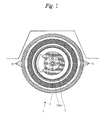
- Figure 1 is a schematic cross-sectional perspective view of a tire with an electric power generation device according to one embodiment of the present invention
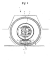
- Figure 2 is a side cross-sectional view of a tire with an electric power generation device according to the one embodiment of the present invention
- Figure 3 is an electric block diagram illustrating a configuration of the electric power generation device illustrated in Figure 1
- Figure 4 is a view for explaining the operation of the electric power generation device according to the one embodiment of the present invention
- Figure 5 is a view for explaining the operation of the electric power generation device according to the one embodiment of the present invention.
- the tire with electric power generation device is constituted of a tire 1 and an electric power generation device 100.
- the tire 1 is a known tubeless radial tire, for example, and constituted of a known captread 2, undertread 3, belts 4A and 4B, carcass 5, inner liner 6 and the like, and held in a vehicle or the like by a rim 7 and a wheel (not illustrated).
- the electric power generation device 100 is constituted of an electric power generation element 10 and a device body 100a; the electric power generation element 10 is connected via a lead 10a to the device body 100a.
- the electric power generation element 10 is constituted of two electrodes 11 and a dielectric elastomer 12 therebetween, and disposed on a side face in the interior of the tire 1.
- the electrodes 11 each have a thickness of several ⁇ m and are attached to both faces of the dielectric elastomer 12.
- the material of the electrodes 11 is, for example, conductive polymer, or one obtained by carbon sputtering or carbon evaporation deposition, or the like; any type of material can be used as long as it functions as a stretchable electrode.
- the dielectric elastomer 12 functions as insulating derivatives between the two electrodes 11, being elastic polymer producing a potential difference between the electrodes 11 when deformation is applied thereto.
- the dielectric elastomer 12 there are elastic polymer containing silicon component, elastic polymer containing acrylic component, and the like; in order to raise permittivity, additives may be contained.
- the thickness of the dielectric elastomer 12 is in a range from several ⁇ m to 1 mm, being set according to required electric energy, placement location or the like.
- the dielectric elastomer 12 may be preliminarily stretched by use of a frame (not illustrated) or the like for holding the dielectric elastomer 12, or may be stretched in a shape forming-vulcanizing process being a tire manufacturing process.
- the electric power generation element 10 having such a configuration is a significantly simple and small-sized element, and functions as a capacitor having excellent stretching properties. Consequently, the electric power generation element 10, being small-sized, can be arranged in the interior of the tire 1. Also, the electric power generation element 10, having excellent stretching properties, can expand and contract sufficiently according to large strain occurring in the tire 1. Thus, since the capacitance of the capacitor varies according to strain applied to the electric power generation element 10, the strain occurring in the tire 1 can be converted into significantly large electric energy, compared to a case where a piezoelectric element is used, or a case where electromotive force by electromagnetic induction is generated.
- the electric power generation element 10 includes two electrodes, but is not limited thereto; the electric power generation element 10 may have a multilayer structure obtained by arranging dielectric elastomer 12 between two or more electrodes 11.
- the electric power generation element 10 is preferably arranged on a side face in the interior of a tire 1 where strain of about 10% occurs, but is not limited thereto; the electric power generation element 10 may alternatively be buried in the interior of a tire 1, or attached to the surface of the captread 2, or arranged in the bottom face in the interior of a tire 1.
- the device body 100a is preferably arranged in a rim 7 or the like where strain does not occur, but not limited thereto.
- a plurality of the electric power generation elements 10 may be arranged on a circle around the rotation axis of the axle of the tire 1 on one or both side faces in the interior of the tire 1.
- strain can be applied to the electric power generation element 10 at all times.
- the device body 100a is also preferably on a circle around the rotation axis of the rim 7 or the like, but not limited thereto.
- the device body 100a is for accumulating via the lead 10a, electric energy produced in the electric power generation element 10 by a potential difference between the electrodes 11.
- a rectifier circuit 110 is constituted of diodes 111 and 112, a capacitor 113 and a resistor 114, and constitutes a known full-wave rectifying circuit.
- the input side of the rectifier circuit 110 is connected via the lead 10a to the electric power generation element 10; the output side of the rectifier circuit 110 is connected to an electrical condenser 120.
- the electrical condenser 120 is constituted of, for example, a secondary battery or a large-capacitance capacitor, and the rectifier circuits 110 are connected thereto in parallel.
- the device body 100a has the same number of rectifier circuits 110 as the electric power generation element 10, and the rectifier circuits 110 are connected to the electrical condenser 120 in parallel. As a result, even when there occurs no strain in the tire 1, electric power can be supplied using electric energy accumulated in the electrical condenser 120.
- the storage unit 131 is constituted of an electrically rewritable nonvolatile semiconductor memory such as EEPROM (electrically erasable programmable read-only memory), and has stored therein information such as supply voltage of an external device 200.
- EEPROM electrically erasable programmable read-only memory
- the CPU 132 is constituted of a known microcomputer and the like, and reads the information stored in the storage unit 131 and sends a control signal for supplying the electric energy accumulated in the electrical condenser 120 to the external device 200.
- the power supply control unit 133 is constituted of, for example, an electrical switch, boost type power supply circuit and the like, and turns on/off the electrical switch based on a control signal from the CPU 132 and thereby converts the electric energy accumulated in the electrical condenser 120 into a voltage required for the circuit operation of the external device 200.
- the resultant voltage is supplied to the external device 200 included in the tire 1, such as a pressure sensor, acceleration sensor, transponder and the like. Consequently, the external device 200 included in the tire 1 can receive operationally sufficient electric power from the electric power generation device 100.
- any technique, cabled or wireless can be used; an antenna or the like for supplying electric power by wireless may be added in the device body 100a, if necessary.
- the rotating tire 1 when the rotating tire 1 makes contacts with the ground surface, it receives force from the ground contact face and thus strain by contraction occurs in the tire 1. Also, when the tire 1 distances itself from the ground surface and is released from the force received from the ground surface, strain by expansion occurs in the tire 1.
- the electric power generation element 10 is arranged on the side face in the interior of the tire 1, and the device body 100a on the rim 7.
- strain f1 by contraction at a ground contact start end of an area r1 which is surrounded by the rotation axis of the tire 1 and a ground contact face s1, and there occurs strain f2 by expansion at a ground contact termination end of the area r1.
- strain f1 by contraction and strain f2 by expansion are simultaneously applied to the one electric power generation element 10.
- the potential difference produced according to strain f1 by contraction and the potential difference produced according to strain f2 by expansion are in an opposite direction to each other, so these potential differences cancel each other and thus the electric power generation element 10 cannot efficiently convert the strain caused by the tire 1 coming into contact with the ground surface into electric energy.
- the area of the ground contact face s1 is determined according to the rotation speed of tire 1, the air pressure within tire 1, the oblateness of tire 1, and the like.
- a length L in a tire circumferential direction of the electric power generation element 10 is set so that the strain by contraction and strain by expansion caused by the rotating tire 1 coming into contact with the ground surface are not simultaneously applied to the single electric power generation element 10, and thus the potential difference produced according to strain f1 by contraction and the potential difference produced according to strain f2 by expansion can be prevented from simultaneously occurring in the single electric power generation element 10 and cancelling each other.
- the external device 200 can receive operationally sufficient electric power from the electric power generation device 100 and can thus operate semipermanently, requiring no power supply.
- the electric power generation elements 10 when a plurality of the electric power generation elements 10 are arranged on a circle around the rotation axis on at least one side face in the interior of the tire 1, strain can be applied to the electric power generation element 10 at all times during rotation of the tire 1; thus the electric power generation element 10 can efficiently convert the strain occurring in the tire 1 into electric energy.
- the simple and small-sized electric power generation device can supply sufficient electric power to the external device included in the tire.
- the tire can be used in a vehicle provided in wheels thereof with electric devices such as pressure sensor, acceleration sensor, transponder and the like.
Landscapes
- Engineering & Computer Science (AREA)
- Mechanical Engineering (AREA)
- Chemical & Material Sciences (AREA)
- Combustion & Propulsion (AREA)
- General Engineering & Computer Science (AREA)
- Power Engineering (AREA)
- General Electrical Machinery Utilizing Piezoelectricity, Electrostriction Or Magnetostriction (AREA)
- Tires In General (AREA)
Abstract
Claims (6)
- Pneumatique (1) comprenant un dispositif de production de puissance électrique (100) pour convertir des contraintes se produisant dans le pneumatique en énergie électrique, où le dispositif de production de puissance électrique (100) comprend:au moins un élément de production de puissance électrique (10) ayant au moins deux électrodes étirables (11) et un polymère élastique (12), agencé entre les électrodes (11) et produisant une différence de potentiel entre les électrodes (11) selon des contraintes appliquées par le pneumatique; et un condensateur électrique (120) pour accumuler l'énergie électrique produite par l'élément de production de puissance électrique (10), et où la longueur, dans une direction circonférentielle du pneumatique (1), de l'élément de production de puissance électrique (10) est réglée de façon que les contraintes (f1) par contraction et les contraintes (f2) par expansion qui sont provoquées par le pneumatique tournant (1) venant en contact avec la surface au sol ne soient pas appliquées simultanément à l'élément de production de puissance électrique unique (10).
- Pneumatique (1) selon la revendication 1, dans lequel le dispositif de production de puissance électrique (100) fournit l'énergie électrique qui s'est accumulée dans le condensateur électrique (120) à un autre dispositif (200) se trouvant dans le pneumatique.
- Pneumatique (1) selon la revendication 1, dans lequel plusieurs éléments de production de puissance électrique (10) sont agencés en cercle autour de l'axe de rotation du pneumatique (1) sur au moins une face latérale dans l'intérieur du pneumatique (1).
- Pneumatique (1) selon la revendication 1, dans lequel le condensateur électrique (120) est constitué d'une batterie secondaire.
- Pneumatique (1) selon la revendication 1, dans lequel le condensateur électrique (120) est constitué d'un condensateur de grande capacité.
- Pneumatique (1) selon la revendication 1, dans lequel les électrodes (11) sont chacune constituées d'un polymère conducteur.
Applications Claiming Priority (2)
| Application Number | Priority Date | Filing Date | Title |
|---|---|---|---|
| JP2005034663A JP2006223054A (ja) | 2005-02-10 | 2005-02-10 | 発電装置を備えたタイヤ |
| PCT/JP2006/302162 WO2006085550A1 (fr) | 2005-02-10 | 2006-02-08 | Pneumatique avec dispositif de production d'electricite |
Publications (3)
| Publication Number | Publication Date |
|---|---|
| EP1848103A1 EP1848103A1 (fr) | 2007-10-24 |
| EP1848103A4 EP1848103A4 (fr) | 2011-01-12 |
| EP1848103B1 true EP1848103B1 (fr) | 2011-10-12 |
Family
ID=36793121
Family Applications (1)
| Application Number | Title | Priority Date | Filing Date |
|---|---|---|---|
| EP06713305A Expired - Lifetime EP1848103B1 (fr) | 2005-02-10 | 2006-02-08 | Pneumatique avec dispositif de production d'electricite |
Country Status (4)
| Country | Link |
|---|---|
| US (1) | US7781942B2 (fr) |
| EP (1) | EP1848103B1 (fr) |
| JP (1) | JP2006223054A (fr) |
| WO (1) | WO2006085550A1 (fr) |
Cited By (1)
| Publication number | Priority date | Publication date | Assignee | Title |
|---|---|---|---|---|
| CN107210648A (zh) * | 2015-01-09 | 2017-09-26 | 朴桂正 | 利用轮胎变形的发电系统 |
Families Citing this family (18)
| Publication number | Priority date | Publication date | Assignee | Title |
|---|---|---|---|---|
| JP4876788B2 (ja) * | 2006-08-25 | 2012-02-15 | 株式会社村田製作所 | 圧電発電装置 |
| US20110043161A1 (en) * | 2009-08-19 | 2011-02-24 | Carlos Manuel Artieda | Electric wheels |
| KR101042426B1 (ko) | 2009-09-25 | 2011-06-16 | 김재인 | 이동 장치의 발전 장치 및 이를 이용한 발전 방법 |
| US20120229001A1 (en) * | 2009-11-17 | 2012-09-13 | Urban Environment Engineering Co., Ltd. | Generator apparatus for a vehicle |
| KR101295670B1 (ko) * | 2009-12-11 | 2013-08-14 | 한국전자통신연구원 | 압전 발전기 |
| US8725330B2 (en) | 2010-06-02 | 2014-05-13 | Bryan Marc Failing | Increasing vehicle security |
| TW201213167A (en) * | 2010-09-28 | 2012-04-01 | Foxsemicon Integrated Tech Inc | Tire and vehicle |
| US9344011B2 (en) | 2014-01-31 | 2016-05-17 | Ford Global Technologies, Llc | Systems and methods for generating power for an electric sub-assembly of a motor vehicle |
| PT107813A1 (pt) * | 2014-07-30 | 2016-10-05 | Miguel Dias Carvalho Rui | Pneu com câmaras de ar para produzir energia elétrica com movimento de automóvel |
| US9694690B2 (en) * | 2014-09-28 | 2017-07-04 | Derek Barton Fisher | Method and apparatus for generation, transmission and storage of electric energy |
| KR101557245B1 (ko) | 2014-12-03 | 2015-10-21 | 성균관대학교산학협력단 | 타이어 코드지용 섬유를 이용한 정전기 에너지 발생장치 |
| US20180079265A1 (en) * | 2015-04-07 | 2018-03-22 | Bridgestone Americas Tire Operations, Llc | Internal tire windmill energy harvester |
| CN104929879B (zh) * | 2015-06-09 | 2017-10-31 | 清华大学 | 一种轮胎内能量回收装置 |
| KR101757065B1 (ko) * | 2015-11-13 | 2017-07-26 | 연암공과대학교산학협력단 | 플랙서블 압전소자를 이용한 자동차 타이어 적용 발전 장치 |
| KR101887809B1 (ko) * | 2017-05-11 | 2018-08-10 | 한국타이어 주식회사 | 접촉대전 자가발전모듈을 포함하는 타이어 |
| US20180337615A1 (en) * | 2017-05-17 | 2018-11-22 | Mohammed Abdulraouf S. ALMAGHRABI | Tire energy recovery system |
| DE102018221053A1 (de) * | 2018-04-05 | 2019-10-10 | Continental Reifen Deutschland Gmbh | Vorrichtung zum Messen einer mechanischen Kraft, umfassend eine erste, zweite, dritte, vierte und fünfte Schicht sowie die Verwendungen der Vorrichtung und Reifen oder technischer Gummiartikel umfassend die Vorrichtung |
| JP7563066B2 (ja) * | 2020-09-14 | 2024-10-08 | 住友ゴム工業株式会社 | 圧電タイヤ |
Family Cites Families (9)
| Publication number | Priority date | Publication date | Assignee | Title |
|---|---|---|---|---|
| JPS6039379A (ja) * | 1983-08-12 | 1985-03-01 | Seitetsu Kagaku Co Ltd | 転動ロス回収装置 |
| JP3580492B2 (ja) * | 1995-07-06 | 2004-10-20 | 日立金属株式会社 | 積層型圧電トランス及びそれを用いた電力変換装置 |
| JPH10229684A (ja) * | 1997-02-14 | 1998-08-25 | Seiko Epson Corp | 圧電発電装置および携帯機器 |
| JP3878280B2 (ja) * | 1997-05-27 | 2007-02-07 | 横浜ゴム株式会社 | タイヤ装着用トランスポンダ及びトランスポンダ装着タイヤ |
| JP2001180553A (ja) * | 1999-12-27 | 2001-07-03 | Usc Corp | 車両用安全灯 |
| EP1275161B1 (fr) * | 2000-04-18 | 2007-03-07 | Pirelli Tyre S.p.A. | Generateur piezo-electrique pour detecteurs situes a l'interieur de pneus de vehicule |
| JP2003153557A (ja) * | 2001-11-12 | 2003-05-23 | Sony Corp | 発電装置、デバイス、動作機械、発電方法 |
| JP2004224069A (ja) | 2003-01-20 | 2004-08-12 | Bridgestone Corp | 発電機 |
| WO2005067073A1 (fr) * | 2003-12-29 | 2005-07-21 | Pirelli Pneumatici S.P.A. | Procede et systeme pour produire de l'energie electrique a l'interieur d'un pneu de vehicule |
-
2005
- 2005-02-10 JP JP2005034663A patent/JP2006223054A/ja active Pending
-
2006
- 2006-02-08 EP EP06713305A patent/EP1848103B1/fr not_active Expired - Lifetime
- 2006-02-08 US US11/815,968 patent/US7781942B2/en not_active Expired - Fee Related
- 2006-02-08 WO PCT/JP2006/302162 patent/WO2006085550A1/fr not_active Ceased
Cited By (1)
| Publication number | Priority date | Publication date | Assignee | Title |
|---|---|---|---|---|
| CN107210648A (zh) * | 2015-01-09 | 2017-09-26 | 朴桂正 | 利用轮胎变形的发电系统 |
Also Published As
| Publication number | Publication date |
|---|---|
| EP1848103A1 (fr) | 2007-10-24 |
| US20090072661A1 (en) | 2009-03-19 |
| EP1848103A4 (fr) | 2011-01-12 |
| WO2006085550A1 (fr) | 2006-08-17 |
| JP2006223054A (ja) | 2006-08-24 |
| US7781942B2 (en) | 2010-08-24 |
Similar Documents
| Publication | Publication Date | Title |
|---|---|---|
| EP1848103B1 (fr) | Pneumatique avec dispositif de production d'electricite | |
| US9908374B2 (en) | Tire module with piezo-electric transducer and tire equipped therewith | |
| JP2005525265A5 (fr) | ||
| KR101765459B1 (ko) | 플렉서블 배터리가 내장된 지갑 | |
| Makki et al. | Battery-and wire-less tire pressure measurement systems (TPMS) sensor | |
| US20170005506A1 (en) | Power storage apparatus | |
| KR101795544B1 (ko) | 배터리가 내장된 가방 | |
| CN1799894A (zh) | 从转动轮胎中的机械能中产生电力的系统及方法 | |
| JP2006056501A (ja) | 圧電素子からの電力変換 | |
| JP4347121B2 (ja) | インホイールモーターシステムに用いるトランスポンダ及びそのトランスポンダを備えた車輪 | |
| US8247952B2 (en) | Wheel with piezoelectric ring and vehicle having same | |
| JP2023015370A (ja) | センサモジュール | |
| EP1897078B1 (fr) | Couplage inductif de signaux de dispositif piézoélectrique | |
| KR101310461B1 (ko) | 자동차 바퀴의 회전 에너지를 이용한 에너지 수집 장치 및 이를 이용한 타이어 공기압 모니터링 시스템 | |
| EP2415619A1 (fr) | Module de détection autoalimenté et système de surveillance de l'état des pneus d'un véhicule doté d'au moins un module de détection autoalimenté | |
| KR20170056147A (ko) | 플랙서블 압전소자를 이용한 자동차 타이어 적용 발전 장치 | |
| CN114761260B (zh) | 包括监测装置的摩托车轮胎 | |
| KR102085006B1 (ko) | 자가 발전 장치 | |
| JP6027420B2 (ja) | 蓄電回路 | |
| EP1728651B1 (fr) | Dispositif electronique monte sur pneu | |
| US10137743B2 (en) | Method and device for operating a tire pressure monitoring device | |
| US9694690B2 (en) | Method and apparatus for generation, transmission and storage of electric energy | |
| JP2009038576A (ja) | データ送信装置 | |
| CN109937526B (zh) | 设有可再充电供电装置的轮胎参数监测系统的电子组件 | |
| WO2020235415A1 (fr) | Source d'alimentation pour système de surveillance de pneu, système de surveillance de pneu et ensemble pneu |
Legal Events
| Date | Code | Title | Description |
|---|---|---|---|
| PUAI | Public reference made under article 153(3) epc to a published international application that has entered the european phase |
Free format text: ORIGINAL CODE: 0009012 |
|
| 17P | Request for examination filed |
Effective date: 20070831 |
|
| AK | Designated contracting states |
Kind code of ref document: A1 Designated state(s): DE FR |
|
| RBV | Designated contracting states (corrected) |
Designated state(s): DE FR |
|
| DAX | Request for extension of the european patent (deleted) | ||
| A4 | Supplementary search report drawn up and despatched |
Effective date: 20101213 |
|
| GRAP | Despatch of communication of intention to grant a patent |
Free format text: ORIGINAL CODE: EPIDOSNIGR1 |
|
| RIC1 | Information provided on ipc code assigned before grant |
Ipc: H02N 2/18 20060101AFI20110324BHEP Ipc: B60C 19/00 20060101ALI20110324BHEP Ipc: F03G 7/08 20060101ALI20110324BHEP |
|
| GRAS | Grant fee paid |
Free format text: ORIGINAL CODE: EPIDOSNIGR3 |
|
| GRAA | (expected) grant |
Free format text: ORIGINAL CODE: 0009210 |
|
| AK | Designated contracting states |
Kind code of ref document: B1 Designated state(s): DE FR |
|
| REG | Reference to a national code |
Ref country code: DE Ref legal event code: R096 Ref document number: 602006025040 Country of ref document: DE Effective date: 20111208 |
|
| PLBE | No opposition filed within time limit |
Free format text: ORIGINAL CODE: 0009261 |
|
| STAA | Information on the status of an ep patent application or granted ep patent |
Free format text: STATUS: NO OPPOSITION FILED WITHIN TIME LIMIT |
|
| 26N | No opposition filed |
Effective date: 20120713 |
|
| REG | Reference to a national code |
Ref country code: DE Ref legal event code: R097 Ref document number: 602006025040 Country of ref document: DE Effective date: 20120713 |
|
| REG | Reference to a national code |
Ref country code: FR Ref legal event code: PLFP Year of fee payment: 11 |
|
| PGFP | Annual fee paid to national office [announced via postgrant information from national office to epo] |
Ref country code: DE Payment date: 20160202 Year of fee payment: 11 |
|
| PGFP | Annual fee paid to national office [announced via postgrant information from national office to epo] |
Ref country code: FR Payment date: 20160108 Year of fee payment: 11 |
|
| REG | Reference to a national code |
Ref country code: DE Ref legal event code: R119 Ref document number: 602006025040 Country of ref document: DE |
|
| REG | Reference to a national code |
Ref country code: FR Ref legal event code: ST Effective date: 20171031 |
|
| PG25 | Lapsed in a contracting state [announced via postgrant information from national office to epo] |
Ref country code: DE Free format text: LAPSE BECAUSE OF NON-PAYMENT OF DUE FEES Effective date: 20170901 Ref country code: FR Free format text: LAPSE BECAUSE OF NON-PAYMENT OF DUE FEES Effective date: 20170228 |