EP1848193A2 - Vorrichtung und Verfahren zur Erkennung von Fehlausrichtungen sowie Computerprogrammprodukt - Google Patents
Vorrichtung und Verfahren zur Erkennung von Fehlausrichtungen sowie Computerprogrammprodukt Download PDFInfo
- Publication number
- EP1848193A2 EP1848193A2 EP07251209A EP07251209A EP1848193A2 EP 1848193 A2 EP1848193 A2 EP 1848193A2 EP 07251209 A EP07251209 A EP 07251209A EP 07251209 A EP07251209 A EP 07251209A EP 1848193 A2 EP1848193 A2 EP 1848193A2
- Authority
- EP
- European Patent Office
- Prior art keywords
- image
- area
- misalignment
- unit
- Prior art date
- Legal status (The legal status is an assumption and is not a legal conclusion. Google has not performed a legal analysis and makes no representation as to the accuracy of the status listed.)
- Ceased
Links
- 238000000034 method Methods 0.000 title claims description 70
- 238000004590 computer program Methods 0.000 title claims description 6
- 238000012937 correction Methods 0.000 claims abstract description 75
- 238000003702 image correction Methods 0.000 claims description 30
- 238000007639 printing Methods 0.000 claims description 7
- 238000012545 processing Methods 0.000 description 105
- 230000008569 process Effects 0.000 description 60
- 238000010586 diagram Methods 0.000 description 16
- 230000008719 thickening Effects 0.000 description 13
- 238000011179 visual inspection Methods 0.000 description 13
- 230000006870 function Effects 0.000 description 6
- 230000004048 modification Effects 0.000 description 5
- 238000012986 modification Methods 0.000 description 5
- 238000005516 engineering process Methods 0.000 description 4
- 239000003086 colorant Substances 0.000 description 3
- 238000004891 communication Methods 0.000 description 2
- 230000008602 contraction Effects 0.000 description 2
- 238000006073 displacement reaction Methods 0.000 description 2
- 238000011156 evaluation Methods 0.000 description 2
- 238000007689 inspection Methods 0.000 description 2
- 230000008859 change Effects 0.000 description 1
- 238000011161 development Methods 0.000 description 1
- 230000018109 developmental process Effects 0.000 description 1
- 230000000694 effects Effects 0.000 description 1
- 238000000605 extraction Methods 0.000 description 1
- 230000012447 hatching Effects 0.000 description 1
- 238000004886 process control Methods 0.000 description 1
- 238000011084 recovery Methods 0.000 description 1
- 230000008439 repair process Effects 0.000 description 1
Images
















Classifications
-
- H—ELECTRICITY
- H04—ELECTRIC COMMUNICATION TECHNIQUE
- H04N—PICTORIAL COMMUNICATION, e.g. TELEVISION
- H04N1/00—Scanning, transmission or reproduction of documents or the like, e.g. facsimile transmission; Details thereof
- H04N1/00002—Diagnosis, testing or measuring; Detecting, analysing or monitoring not otherwise provided for
-
- H—ELECTRICITY
- H04—ELECTRIC COMMUNICATION TECHNIQUE
- H04N—PICTORIAL COMMUNICATION, e.g. TELEVISION
- H04N1/00—Scanning, transmission or reproduction of documents or the like, e.g. facsimile transmission; Details thereof
- H04N1/46—Colour picture communication systems
- H04N1/56—Processing of colour picture signals
- H04N1/58—Edge or detail enhancement; Noise or error suppression, e.g. colour misregistration correction
Definitions
- the present invention relates to a misalignment detecting apparatus, a misalignment detecting method, and a computer program product.
- Japanese Patent Application Laid-Open No. 2005-33656 discloses a technology in which a differential image is generated from two images.
- a misalignment detecting apparatus that detects misalignment of a second image with respect to a first image, includes a digitizing unit that digitizes images to obtain the first image and the second image, an image generating unit that generates a third image indicating misalignment between the first image and the second image in a preset mode based on misalignment between corresponding points on the first image and the second image, and an output unit that visually outputs the third image.
- a misalignment detecting method for detecting misalignment of a second image with respect to a first image includes digitizing images to obtain the first image and the second image, generating a third image indicating misalignment between the first image and the second image in a preset mode based on misalignment between corresponding points on the first image and the second image, and outputting visually the third image.
- a computer program product includes a computer usable medium having computer readable program codes embodied in the medium that, when executed, cause a computer to implement the above method.
- Fig. 1 is a schematic of an image processing system 1 according to a first embodiment of the present invention.
- the image processing system 1 includes an image processing apparatus 10, a server 20, a first printer 21, a second printer 22, and a scanner 30.
- the server 20 transmits print data 200 to the first printer 21 and the second printer 22.
- the first printer 21 and the second printer 22 each obtain the print data 200 for output onto a print medium such as paper.
- the scanner 30 reads a first print 210 output from the first printer 21 and a second print 220 output from the second printer 22.
- the image processing apparatus 10 generates a misalignment display image visualizing misalignment between a first print image and a second print image obtained through digitization by the scanner. Then, a misalignment display image 230 is caused to be displayed on a display 12. By visually inspecting only this misalignment display image, an operator can check a matching state between the first print 210 and the second print 220.
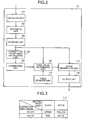
- Fig. 2 is a functional block diagram of the image processing apparatus 10.
- the image processing apparatus 10 includes an obtaining unit 100, a binarizing unit 102, a storage unit 104, a correction-coefficient calculating unit 106, a correcting unit 108, a pixel-value determining unit 110, a table storage unit 112, an image generating unit 114, and an output unit 116.
- the obtaining unit 100 obtains images read by the scanner 30. Specifically, the obtaining unit 100 obtains a first print image obtained through digitization of the first print 210 printed by the first printer 21, and a second print image obtained through digitization of the second print 220 printed by the second printer 22.
- the binarizing unit 102 binarizes the print images obtained by the obtaining unit 100. Specifically, for example, with a predetermined brightness as a threshold, a pixel with brightness higher than the threshold is taken as white, whilst a pixel with brightness lower than the threshold is taken as black.
- the storage unit 104 stores therein the first print image and the second print image binarized by the binarizing unit 102.
- the correction-coefficient calculating unit 106 calculates correction coefficients between the first print image and the second print image.
- correction coefficients ("a" to "f") are calculated by using the following Equation 1, where the correction coefficients ("a" to "f") are coefficients for use in calculating, from a pixel position of one image, its corresponding position of another image.
- X Y ( a b c d ) ( x y ) + e f
- misalignment is represented by "
- Expansion or contraction is represented by "
- Distortion is represented by "
- the scheme according to the documents mentioned above is to calculate correction coefficients after automatically extracting corresponding points of two images (points that are supposed to be located at the same position). Specifically, a sequence of black pixel components is extracted, and then a corresponding point in the extracted black pixel components is extracted. In another example, corresponding coordinates are extracted. However, there may be the case where extraction of the corresponding point may fail. In that case, the corresponding point can be entered by the operator in a form of position coordinates, thereby reliably finding correction coefficients based on this information.
- the correcting unit 108 uses the correction coefficients calculated by the correction-coefficient calculating unit 106 to correct either one of the first print image and the second print image. Specifically, the position of each pixel of the target image is re-calculated with the correction coefficients. It is assumed in the embodiment that the first print image is corrected, and the first print image after correction is referred to as a corrected first image.
- the pixel-value determining unit 110 compares the second print image stored in the storage unit 104 and the corrected first image obtained by the correcting unit 108 to determine a pixel value of each pixel according to a matching state. At this time, a pixel-value determination table 113 stored in the table storage unit 112 is referred to.
- Fig. 3 is an example of contents of the pixel-value determination table 113.
- the pixel-value determination table 113 contains pixel values of the corrected first image, pixel values of the second print image, and pixel values defined by these values in a corresponding manner. As shown in Fig. 3, according to the pixel-value determination table 113, when the pixel value of the corrected first image represents black and the pixel value of the second print image represents black, a pixel value assigned to that pixel represents green. When the pixel value of the corrected first image represents black and the pixel value of the second print image represents white, a pixel value assigned to that pixel represents yellow.
- a pixel value assigned to that pixel represents red.
- a pixel value assigned to that pixel represents white.
- the image generating unit 114 generates a misalignment display image based on the second-print image stored in the storage unit 104 and the corrected first image obtained by the correcting unit 108.
- Each pixel of the misalignment display image is assigned the pixel value determined by the pixel-value determining unit 110.
- the output unit 116 outputs the misalignment display image generated by the image generating unit 114 to the outside, specifically, to the display 12.
- the display 12 displays the output misalignment display image.
- Fig. 4 is a flowchart of image processing performed by the image processing system 1.
- the server 20 transmits the print data 200 to the first printer 21 (step S100).
- the first printer 21 prints the received print data 200 on a print medium (step S102).
- the server 20 transmits the print data 200 to the second printer (step S104).
- the second printer 22 prints the received print data 200 on a print medium (step S106) .
- the scanner 30 reads the print obtained by the first printer 21 and the second print obtained by the second printer 22 (step S108). That is, these prints are converted to a data form to obtain a first print image and a second print image.
- the image processing apparatus 10 performs a misalignment display process based on the first print image and the second print image (step S110). With this, the image processing, i.e., misalignment-display-image generating process, by the image processing system 1 is completed.
- Fig. 5 is a detailed flowchart of the misalignment display process shown in Fig. 4.
- the binarizing unit 102 binarizes the first and second print images (step 5120).
- the correction-coefficient calculating unit 106 calculates a correction coefficient (step S122).
- the correcting unit 108 corrects the first print image to obtain a corrected first image (step S124).
- the pixel-value determining unit 110 determines a pixel value of each pixel according to a matching state of the corresponding pixels between the corrected first image and the second print image (step S126).
- the image generating unit 114 generates a misalignment display image (step S128).
- the pixel values determined by the pixel-value determining unit 110 are assigned to the relevant pixels.
- the output unit 116 outputs the misalignment display image to the display 12 (step S130).
- Fig. 6 is a schematic for explaining the process of correcting the first print image (at step S124 in Fig. 5). For example, when the image is misaligned in a horizontal direction, the image is shifted in a horizontal direction through recalculation based on the correction coefficients as shown in Fig. 6.
- a subtle mismatch between images such as a slight misalignment of a ruled line, does not pose a problem. For this reason, prior to generating a misalignment display image, the first print image is corrected. This allows generation of a misalignment display image from which only a problematic mismatch between images can be ascertained.
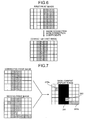
- Fig. 7 is a schematic for explaining the process of generating the misalignment display image (at step S128 in Fig. 5).
- a pixel value representing green is assigned to an area 241 in which pixels of the corrected first image and those of the second print image are both black.
- a pixel value representing yellow is assigned to an area 242 in which pixels of the corrected first image are black and those of the second print image are white.
- a pixel value representing red is assigned to areas 243a and 243b in which pixels of the corrected first image are white and those of the second print image are black.
- Colors can be set in the pixel-value determination table 113 so that a conspicuous color is assigned to an area indicating a difference to be mainly checked. This facilitates a visual inspection check.
- an area with the pixel value of the corrected first image representing white and the pixel value of the second print image representing black is made conspicuous more than an area with the pixel value of the corrected first image representing black and the pixel value of the second print image representing white.
- red is assigned to the area with the pixel value of the corrected first image representing white and the pixel value of the second print image representing black.
- yellow is assigned to the area with the pixel value of the corrected first image representing black and the pixel value of the second print image representing white. Since yellow is difficult to differentiate from white in appearances, red is relatively conspicuous than yellow. In this manner, by assigning a color with a large difference in hue, brightness, and others, visual inspection can be facilitated.
- Fig. 8 is an example of a misalignment display image. From a corrected first image 212 and a second print image 222 shown in Fig. 8, a misalignment display image 232 is generated. Between the corrected first image 212 and the second print image 222, characters 250 and 252 are misaligned. Therefore, in the misalignment display image 232, yellow is assigned to the character 252 corresponding to that of the corrected first image 212, whilst red is assigned to the character 250 corresponding to that of the second print image 222.
- Fig. 9 is a schematic of a hardware configuration of the image processing apparatus 10.
- the image processing apparatus 10 includes, as hardware, a Read-Only Memory (ROM) 52 that stores therein computer programs such as an image processing program for image processing performed by the image processing apparatus 10, a Central Processing Unit (CPU) 51 that control each unit of the image processing apparatus 10 according to the computer programs in the ROM 52, a Random Access Memory (RAM) 53 that stores therein various data required for controlling the image processing apparatus 10, a communication interface (I/F) 57 connected to a network for communication, and a bus 62 connecting the respective units.
- ROM Read-Only Memory
- CPU Central Processing Unit
- RAM Random Access Memory
- the image processing program can be provided as being recorded on a computer-readable recording medium, such as a Compact Disk Read-Only Memory (CD-ROM), a floppy (registered trademark) disk (FD), a Digital Versatile Disk (DVD), as a file in an installable or executable format.
- a computer-readable recording medium such as a Compact Disk Read-Only Memory (CD-ROM), a floppy (registered trademark) disk (FD), a Digital Versatile Disk (DVD), as a file in an installable or executable format.
- the image processing program is loaded from the recording into a main storage device of the image processing apparatus 10 for execution.
- a main storage device of the image processing apparatus 10 for execution.
- the image processing program can also be stored in a computer connected to a network, such as the Internet, and downloaded via the network.
- the first printer 21 and the second printer 22 output the same print data 200 to the print medium
- these printers can output different pieces of print data. In this case, these pieces of print data have to be those from which the same print result is expected.
- the image processing apparatus 10 includes the binarizing unit 102.
- the binarizing unit 102 is not necessary when image data obtained by the obtaining unit 100 are binary data.
- the output unit 116 outputs it to, for example, the first printer 21 to obtain a corresponding print. In this case, by visually checking the print, an operator can determine the image matching state.
- the image processing system generates a misalignment display image indicating misalignment between the prints of the first printer 21 and the second printer 22.
- the misalignment display image can be generated to indicate misalignment between images printed on print media delivered from different paper-feeding trays on the same printer. With this, an operator can visually check misalignment of images with respect to each paper-feeding tray.
- the image processing system generates a misalignment display image in which different pixel values are assigned according to the pixel matching state.
- the misalignment display image is not so limited and can be generated in a different manner as long as an image of a different format is generated according to the pixel matching state.
- a misalignment display image can indicate misalignment by circling it, hatching it, or presenting a message indicative of the presence of misalignment.
- Fig. 10 is a functional block diagram an image processing apparatus 13 according to a second embodiment of the present invention.
- the image processing apparatus 13 is in many respects similar to the image processing apparatus 10 except for the presence of a misalignment calculating unit 120 and a misalignment amount output unit 122.
- the misalignment calculating unit 120 calculates, based on the correction coefficients, a misalignment amount in the misalignment display image generated by the image generating unit 114. Specifically, coefficients (e, f) in Equation 1 are calculated.
- the misalignment amount output unit 122 outputs the misalignment amount calculated by the misalignment calculating unit 120.
- Fig. 11 is an example of screen display of misalignment amount output from the misalignment amount output unit 122 on the display 12.
- ID image identification
- a misalignment display image corresponding to the first print image and the second print image for which the misalignment amount has been calculated and the calculated misalignment amount are displayed. Based on these values, the operator sets to the first printer 21 a misalignment adjusting amount for correcting the misalignment. With this, misalignment between the first print image and the second print image can be corrected.
- Fig. 12 is a flowchart of image processing according to the second embodiment.
- the misalignment calculating unit 120 receives this specification and calculates a misalignment amount (step S114).
- the misalignment amount output unit 122 outputs the misalignment amount calculated by the misalignment calculating unit 120 (step S116). The image process by the image processing system 1 according to the second embodiment is thus completed.
- a misalignment adjusting amount for correcting the misalignment can be calculated and output.
- the operator can set the misalignment adjusting amount in the first printer 21.
- the misalignment adjusting amount is calculated from the misalignment amount, and is a value defined according to the model and individual capability of the first printer 21.
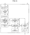
- Fig. 13 is a functional block diagram of an image processing apparatus 14 according to a third embodiment of the present invention.
- the image processing apparatus 14 is in many respects similar to the image processing apparatus 10 except for the presence of a line-width changing unit 124.
- the line-width changing unit 124 thickens a line in either one of the corrected first image and the second print image.
- the image in which a line is to be thickened may be any one of the corrected first image and the second print image.
- which image is to be processed is set in advance.
- the pixel-value determining unit 110 determines a pixel value by using the image after thickening the line by the line-width changing unit 124.
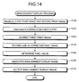
- Fig. 14 is a detailed flowchart of a misalignment display process performed by the image processing apparatus 14. After correcting the first print image (step S124), the line-width changing unit 124 thickens a line in either one of the corrected first image and the second print image (step S140).
- the pixel-value determining unit 110 determines a pixel value based on the matching state between one image with its line thickened by the line-width changing unit 124 and the other image (step S126). Specifically, when the line in the corrected first image is thickened, the corrected first image after the thickening process and the second print image are used. On the other hand, when the line in the second print image is thickened, the corrected first image and the second print image after processing are used.
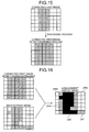
- Fig. 15 is a schematic for explaining the process of thickening a line in the corrected first image (at step S140 in Fig. 14).
- the line is thickened on both sides, right and left, by one pixel. In this manner, the line is thickened to a predetermined width.
- the degree of thickening is arbitrary.
- Fig. 16 is a schematic for explaining the process of generating a misalignment display image (at step S128 in Fig. 14) according to the third embodiment.
- green is assigned to an area 245 in which both pixels of the corrected first image after the thickening process and the second print image are black.
- Yellow is assigned to areas 246a, 246b, and 246c in which pixel values of the corrected first image after the thickening process represent black and those of the second print image represent white.
- Red is assigned to an area 247 in which pixel values of the corrected first image after the thickening process represent white and those of the second print image represent black.
- an inconspicuous color is assigned to the areas, such as the areas 246a, 246b, and 246c in Fig. 16, in which the image subjected to the thickening process is black, thereby making a portion with an unproblematic misalignment inconspicuous. With this, only the portion where misalignment to be detected through visual inspection occurs can be made conspicuous.
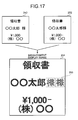
- Fig. 17 is an example of a misalignment display image. From a corrected first image after the thickening process and the second print image 222 shown in Fig. 17, a misalignment display image 234 is generated. Because the corrected first image has been subjected to the thickening process, there are many pixels that are black only in the corrected first image 212. In the misalignment display image 234, there are many yellow areas surrounding each green character. However, yellow is inconspicuous, and these areas are difficult to differentiate in visual inspection. Such a subtle displacement does not pose a problem, and that is why such an inconspicuous color is assigned.
- the red area is present on the right side of "1".
- this area is preferably made inconspicuous.
- the area on the right side of "1" is also a yellow area. In this manner, by performing a process of thickening lines in advance, the amount of red areas can be reduced. Therefore, the conspicuous color can be assigned only to the areas to be noted.
- red is assigned only to a character area 256 and an area of "-" next to "1000". These areas are those to be noted.
- the conspicuous color can be assigned only to the areas to be noted.
- a line in the corrected first image when a line in the corrected first image is to be thickened, a line in the first print image before correction can be thickened.
- Fig. 18 is a functional block diagram of an image processing apparatus 15 according to a fourth embodiment of the present invention.
- the image processing apparatus 15 is in many respects similar to the image processing apparatus 10 except for the presence of a difference calculating unit 126.
- the difference calculating unit 126 calculates a degree of difference between the first print image and the second print image. Specifically, the number of pixels not matching the corresponding pixel values is counted and, if the number of pixels is equal to or larger than a threshold, no match is determined.
- the output unit 116 determines that these images do not match when the degree of difference calculated by the difference calculating unit 126 is equal to or larger than a threshold, and then outputs a misalignment display image generated from these images.
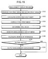
- Fig. 19 is a detailed flowchart of a misalignment display process performed by the image processing apparatus 15.
- the difference calculating unit 126 calculates a degree of difference between the first print image and the second print image (step S150). If they do not match (No at step S152), the output unit 116 outputs the misalignment display image generated by the image generating unit 114 (step S130). On the other hand, it is determined that they match (Yes at step S152), it is determined that no misalignment to be noted is present in these images, and the misalignment display image generated from these images is not output.
- the image processing i.e., misalignment-display-image generating process, is thus completed (step S110).
- the misalignment display image is output to prompt the operator for visual inspection only when it is determined that the first print image and the second print image do not match.
- the process load on the operator can be reduced.
- a misalignment display image in which matching can be determined by the image processing apparatus 15 even without performing visual inspection is not output. Therefore, efforts of visual inspection can be reduced.
- the degree of difference is calculated based on a misalignment display image generated from the first print image and the second print image and the shape of each image contained in the first print image or the second print image.
- Figs. 20A and 20B are schematics for explaining the process of calculating a difference degree according to the modification example.
- the state shown on the left side of Fig. 20A is such that an image in the first print image and an image in the second print image do not match but are superposed each other.
- the remaining portion has a shape as shown on the right side of the drawing.
- the state shown on the left side of Fig. 20B is such that an image in the first print image and an image in the second print image are not superposed each other at all.
- the remaining portion has a shape as shown on the right side of the drawing. That is, the shape identical to that of the original image is left.
- the difference calculating unit 126 can calculate a degree of difference between this remaining portion and the original image. With this value, the degree of matching between the first print image and the second print image can be determined.
- a misalignment display image is output when the degree of difference is equal to or larger than the threshold and no match is determined.
- the degree of difference and the misalignment display image ID that identifies the misalignment display image can be output in an associated manner.
- Fig. 21 is an example of screen display on the display 12. On the display 12, the misalignment display image ID and the degree of difference are displayed.
- Display can be made with sorting in the order in which the degree of difference is lower or higher. Further, by specifying an image ID, a corresponding misalignment display image may be displayed. With these, the operator can visually inspect only the misalignment display image determined as requiring visual inspection.
- a misalignment display image with a degree of difference equal to or larger than the predetermined threshold can be identified and displayed so that it can be ascertained that the degree of difference is equal to or larger than the threshold.
- Information indicating that the degree of difference is equal to or larger than the threshold may also be displayed.
- an image ID corresponding to an image with a degree of difference equal to or larger than the threshold can be displayed with a typeface and a color that are different from those of the other image IDs.
- the misalignment display image is output when the compared images do not match based on the calculated degree of difference. At this time, an image indicative of a warning can be further displayed, or a warning sound can be produced from a loudspeaker.
- the image processing apparatus need not include the pixel-value determining unit 110 and the table storage unit 112.
- the image generating unit 114 generates a binary misalignment display image.
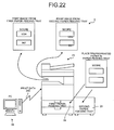
- Fig. 22 is a schematic of an image processing system 2 according to a fifth embodiment of the present invention.
- the image processing system 2 includes the server 20 and a Multifunction Product (MFP) 23.
- the MFP 23 has a printer function and a scanner function.
- the operator first adjusts position of a print image output from a first paper-feeding tray 24, and then the image processing system 2 adjusts misalignment between print images output from the first paper-feeding tray 24 and a second paper-feeding tray 25.
- a print position may be varied depending on the paper-feeding tray, and such misalignment can be adjusted.
- a numerical character is to be printed within a print target frame of preprinted paper, such as a standard form.
- preprinted paper such as a standard form.
- the position is adjusted with settings of the printer so that a print position is aligned for a particular paper-feeding tray, another alignment is required for another paper-feeding tray.
- the first paper-feeding tray 24 and the second paper-feeding tray 25 have stored thereon preprinted paper media.
- the print data 200 is printed on each of the print media in the first paper-feeding tray 24 and the second paper-feeding tray 25. Then, a first print with the print data 200 printed onto a first print medium delivered from the first paper-feeding tray 24 and a second print with the print data 200 printed onto a second print medium delivered from the second paper-feeding tray 25 are read by a scanner. Then, based on misalignment between these prints, the misalignment is corrected.
- Fig. 23 is a functional block diagram of the MFP 23.
- the MFP 23 includes the obtaining unit 100, the binarizing unit 102, the storage unit 104, the correction-coefficient calculating unit 106, and a position adjusting unit 128.
- the obtaining unit 100, the binarizing unit 102, the storage unit 104, and the correction-coefficient calculating unit 106 have functions similar to those according to the other embodiments.
- the position adjusting unit 128 adjusts a print position based on the correction coefficients calculated by the correction-coefficient calculating unit 106 when a print medium is delivered from either one of the first paper-feeding tray 24 and the second paper-feeding tray 25.
- Fig. 24 is a flowchart of image processing performed by the image processing system 2.
- the server 20 transmits print data to the MFP 23 (step S200).
- the MFP 23 outputs the print data onto a print medium delivered from the first paper-feeding tray 24 to obtain a first print (step 5202).
- a print position is set in advance so as to be an appropriate position.
- the print data is actually printed onto a print medium as preprinted paper. Based on the print result, the operator performs fine adjustment by trial and error with the settings of the MFP.
- the MFP 23 outputs the print data onto a print medium delivered from the second paper-feeding tray 25 to obtain a second print (step S204).
- the first print and the second print are read by the scanner (step S206).
- the prints are mounted on the scanner with caution so that the setting position of the first print matches the setting position of the second print. For example, sheets of paper are aligned with an edge of a table of the scanner.
- a print-position adjusting process is performed based on a first print image obtained by digitizing the first print and a second print image obtained by digitizing the second print (step S208). The image processing is thus completed.
- Fig. 25 is a detailed flowchart of the print-position adjusting process shown in Fig. 24.
- the binarizing unit 102 binarizes the first print image and the second print image (step S220).
- the correction-coefficient calculating unit 106 calculates correction coefficients based on the first print image and the second print image (step S222).
- the position adjusting unit 128 adjusts the print position for the second print medium according to the settings of the MFP (step 5224). The print-position adjusting process is thus completed.
- the operator adjusts the print position by trial and error for the first tray, whilst the print position can be adjusted for the second tray based on the correction coefficients. With this, an efficient adjusting process can be achieved.
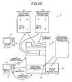
- Fig. 26 is a schematic of an image processing system 3 according to a sixth embodiment of the present invention.
- the image processing system 3 includes the server 20, an image processing apparatus 16, and an MFP 26.
- the MFP 26 has a scanner function and a printer function.
- the MFP 26 prints print data on a print medium delivered from a first paper-feeding tray 27 to obtain a first print, and prints the print data on a print medium delivered from a second paper-feeding tray 28 to obtain a second print. Then, the first print and the second print are read by a scanner to obtain a first print image and a second print image.
- the image processing apparatus 16 obtains the first print image and the second print image from the MFP 26. Then, based on the first print image and the second print image, an adjustment amount for adjusting the print position for printing onto the print medium delivered from the second paper-feeding tray 28 is calculated and output. That is, part of the function performed by the MFP 23 according to the fifth embodiment is performed by the image processing apparatus 16.
- Fig. 27 is a functional block diagram of the image processing apparatus 16 according to the sixth embodiment.
- the image processing apparatus 16 includes the obtaining unit 100, the binarizing unit 102, the storage unit 104, the correction-coefficient calculating unit 106, and an adjustment-information output unit 130.
- the adjustment-information output unit 130 calculates an adjustment amount from the correction coefficients calculated by the correction-coefficient calculating unit 106 to output print position adjustment information including the adjustment amount.
- the display 12 displays the print position adjustment information output from the adjustment-information output unit 130. Specifically, on the display 12, image IDs of the first print image and the second print image to be processed and the print position adjustment amount calculated from these images are displayed.
- the operator refers to this display to set the displayed print position adjustment amount to the MFP 26, thereby adjusting the position when printing onto the print medium delivered from the second paper-feeding tray 28.
- Fig. 28 is a functional block diagram of an image processing apparatus 17 in an image processing system according to a seventh embodiment of the present invention.
- the image processing apparatus 17 calculates, in addition to the image correction coefficients, which are correction coefficients for the entire image, area correction coefficients, which are local correction coefficients for partial areas in an image. Then, based on such area correction coefficients, the partial area is corrected.
- the image processing apparatus 17 includes the obtaining unit 100, the binarizing unit 102, the storage unit 104, the pixel-value determining unit 110, the table storage unit 112, the image generating unit 114, and the output unit 116, as well as an image-correction-coefficient calculating unit 140, an image correcting unit 142, an instruction receiving unit 150, an image-correction-coefficient evaluating unit 152, an area setting unit 154, an area-correction-coefficient calculating unit 156, and an area correcting unit 158.
- the image-correction-coefficient calculating unit 140 and the image correcting unit 142 correspond to the correction-coefficient calculating unit 106 and the correcting unit 108, respectively, according to any of the other embodiments. That is, the image-correction-coefficient calculating unit 140 calculates image correction coefficients, which are correction coefficients for the entire image. Here, the image correction coefficients correspond to correction coefficients according to any of the other embodiments.
- the image correcting unit 142 corrects either one of the first print image and the second print image based on the image correction coefficients. Here, the first print image is corrected in the embodiment.
- the instruction receiving unit 150 receives from an operator an area correction instruction.
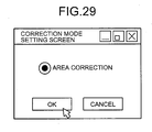
- the area correction instruction is an instruction for correction not for the entire image but by units of a predetermined area in the image. For example, if the image processing apparatus 17 includes a widow system, a setting screen as shown in Fig. 29 is presented to the operator. Then, an instruction of whether an area correction is to be performed is received from the operator.
- the image-correction-coefficient evaluating unit 152 evaluates the image correction coefficients calculated by the image-correction-coefficient calculating unit 140. This is to determine whether the first print image can be corrected with a sufficient accuracy only with the image correction coefficients.
- a slight distortion is unavoidable due to the condition of a paper-feeding device at the time of image pickup by the scanner, such a subtle distortion does not pose a problem.
- a large local distortion may pose a problem as misalignment, if a portion with such a subtle distortion is displayed as misalignment, a misalignment area to be primarily handled becomes inconspicuous. To get around this, such a subtle local distortion is corrected in advance.
- the image-correction-coefficient evaluating unit 152 compares the first print image after image correction with the image correction coefficients and corresponding pixel values of the second print image, and when the number of matching pixels is equal to or larger than a predetermined threshold, determines that the positions of the images become matched through image correction.
- the area setting unit 154 sets first areas, which are areas in the first print image after image correction. Specifically, the first print image is divided into rectangular areas each having a preset size. A plurality of areas obtained through this division are each set as a first area.
- the area-correction-coefficient calculating unit 156 specifies a second area from the second print image corresponding to an arbitrary first area obtained by the area setting unit 154. Then, an area correction coefficient, which is a correction coefficient between the first area and the second area, is calculated.
- an area in the second print image that is possibly a second area is first set as a second area candidate.
- the second area candidate is an arbitrary area having the same size and shape as those of the first area.
- the position of the second area candidate in the second print image is set near the position of the first area in the first print image. Furthermore, by shifting by one pixel from the position corresponding to the first area, a plurality of second area candidates is set.
- a setting range of the second area candidates is defined as being within a predetermined distance from a reference point, which is, for example, the position corresponding to the first area. In this manner, the range searched for second area candidates is set in advance.
- the area-correction-coefficient calculating unit 156 calculates a degree of difference between each of the second area candidates and the first area. Specifically, the number of pixels that do not match in a binary image is calculated as a degree of difference. A second area candidate with the smallest degree of difference is determined as a second area corresponding to the first area.
- an accumulated value of absolute values of corresponding pixel values may be calculated as a degree of difference.
- misalignment due to distortion such as expansion or contraction, rotation, or others
- a degree of difference between the first area expanded or contracted or rotated, for example, and the second area candidate may be calculated.
- the area-correction-coefficient calculating unit 156 calculates a correction coefficient between thus determined second area and the first area as an area correction coefficient.
- the area correcting unit 158 corrects the area in the corrected first print image based on the area correction coefficient calculated by the area-correction-coefficient calculating unit 156.
- the pixel-value determining unit 110 determines a pixel value based on the first print image after the correction by the area correcting unit 158 and the second print image.
- Fig. 30 is a flowchart of a misalignment display process performed by the image processing apparatus 17.
- the binarizing unit 102 binarizes the first print image and the second print image (step S160).
- the image-correction-coefficient calculating unit 140 calculates correction coefficients, i.e., image correction coefficients, for the first print image and the second print image after binarization (step S162).
- the image correcting unit 142 corrects the first print image by using the image correction coefficient (step S164) . That is, image correction is performed.
- the image-correction-coefficient evaluating unit 152 evaluates the image correction coefficients calculated by the image correcting unit 142 (step S168).
- the area setting unit 154 sets areas (step S172). For example, as shown in Fig. 31, four areas obtained by dividing the first print image into four are set as first areas. In this case, areas of the second print image that correspond to the respective first areas are further set as second area candidates. Still further, based on the degree of difference, a second area corresponding to each first area is set.
- the area-correction-coefficient calculating unit 156 calculates a correction coefficient between an arbitrary first area set by the area setting unit 154 and its corresponding second area, that is, an area correction coefficient (step S174). This process is performed for every first area.
- the area correcting unit 158 uses each area correction coefficient to correct the corresponding first area (step S178). In the example of Fig. 31, if area correction coefficients have been calculated for all of the four first areas (Yes at step S176), the process control proceeds to step S178.
- the pixel-value determining unit 110 determines a pixel value based on the first print image after area correction and the second print image (step S182).
- the image generating unit 114 generates a misalignment display image based on the pixel value determined by the pixel-value determining unit 110 (step S184).
- the output unit 116 outputs the misalignment display image (step S186) . The process is thus completed.
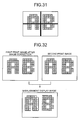
- Fig. 32 is a schematic of a first print image after image correction, a second print image, and a misalignment display image generated therefrom.
- a character "B" on the right side of the first print image after image correction matches that of the second print image but a character "A" on the left side of the first print image after image correction does not match that of the second print image.
- the character "B" which does not require correction, has to be corrected, thereby causing misalignment of the character "B”.
- area correction is performed, thereby correcting only the misalignment of the character "A".
- Fig. 34 is a schematic of a first print image after shifting, i.e., a first print image after area correction, a second print image, and a misalignment display image generated therefrom.
- the first print image is subjected to not only image correction but also area correction, thereby matching the character positions of "A" and "B". This can eliminate an unnecessary misalignment due to a local distortion, thereby providing the operator with a misalignment display image with only the portion having a significant difference in the print result being displayed in a visually-inspectable form.
- rectangles defined from the first print image after image correction are set as first areas
- a sequence of black pixel components can be found from the first print image after image correction, and these black pixel components can be set as areas.
- a rectangle circumscribing the black pixel components can be set as an area. In this case, area correction can be performed only on the obtained first area.
- area correction is performed after image correction.
- image correction can be skipped when area correction is performed.
- area correction is performed in the same manner as explained above to present an appropriate misalignment display image to an operator.
- Fig. 35 is a functional block diagram of an image processing apparatus 18 in an image processing system according to an eighth embodiment of the present invention.
- the image processing apparatus 18 is basically similar in functional configuration to the image processing apparatus 17 except that it does not include an image-correction-coefficient evaluating unit.
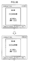
- the image processing apparatus 18 once generates and outputs a misalignment display image from the first print image after image correction and the second print image. Then, when an area correcting instruction is issued from the operator at this time, according to this instruction, area correction is performed on the first print image after image correction. Then, a misalignment display image is generated from the first print image after area correction and the second print image for output.
- a "perform area alignment” button is displayed together with the misalignment display image generated from the first print image after image correction and the second print image.
- the instruction receiving unit 150 receives an area correction instruction.
- Fig. 37 is a flowchart of a misalignment display process performed by the image processing apparatus 18. Processes from steps S120 to S130 are similar to those in the misalignment display process performed by the image processing apparatus 10, that is, those from steps S120 to S130 shown in Fig. 5.
- the area setting unit 154 sets first areas and second areas (step S302).
- the area-correction-coefficient calculating unit 156 calculates an area correction coefficient for each first area (steps S304 and S306). Then, the area-correction-coefficient calculating unit 156 performs area correction (steps S308 and S310). Then, a misalignment display image after area correction is generated (steps S312 to S316).
- the processes from steps S302 to S316 are similar to steps S172 to S186, respectively, according to the seventh embodiment explained with reference to Fig. 31.
- the image system according to the embodiments for a change in output settings due to replacement of printers or others, the settings can be simplified, and customer convenience can be improved.
- misalignment display image Moreover, a subtle, local distortion is not displayed as misalignment, and only a noteworthy difference between the images can be easily found in the misalignment display image.
Landscapes
- Engineering & Computer Science (AREA)
- Multimedia (AREA)
- Signal Processing (AREA)
- Health & Medical Sciences (AREA)
- Biomedical Technology (AREA)
- General Health & Medical Sciences (AREA)
- Image Processing (AREA)
- Accessory Devices And Overall Control Thereof (AREA)
- Image Analysis (AREA)
- Apparatus For Radiation Diagnosis (AREA)
Applications Claiming Priority (2)
| Application Number | Priority Date | Filing Date | Title |
|---|---|---|---|
| JP2006099492 | 2006-03-31 | ||
| JP2007010737A JP4750047B2 (ja) | 2006-03-31 | 2007-01-19 | 位置ずれ検出装置、位置ずれ検出方法、位置ずれ検出プログラムおよび記録媒体 |
Publications (2)
| Publication Number | Publication Date |
|---|---|
| EP1848193A2 true EP1848193A2 (de) | 2007-10-24 |
| EP1848193A3 EP1848193A3 (de) | 2008-07-16 |
Family
ID=38476039
Family Applications (1)
| Application Number | Title | Priority Date | Filing Date |
|---|---|---|---|
| EP07251209A Ceased EP1848193A3 (de) | 2006-03-31 | 2007-03-21 | Vorrichtung und Verfahren zur Erkennung von Fehlausrichtungen sowie Computerprogrammprodukt |
Country Status (4)
| Country | Link |
|---|---|
| US (1) | US8724925B2 (de) |
| EP (1) | EP1848193A3 (de) |
| JP (1) | JP4750047B2 (de) |
| CN (1) | CN101046885B (de) |
Cited By (1)
| Publication number | Priority date | Publication date | Assignee | Title |
|---|---|---|---|---|
| TWI695441B (zh) * | 2013-12-02 | 2020-06-01 | 日商大亨股份有限公司 | 工件處理裝置、工件輸送系統 |
Families Citing this family (13)
| Publication number | Priority date | Publication date | Assignee | Title |
|---|---|---|---|---|
| JP4950550B2 (ja) * | 2006-04-21 | 2012-06-13 | 株式会社東芝 | パターン合わせずれ計測方法およびプログラム |
| JP4960897B2 (ja) * | 2008-01-30 | 2012-06-27 | 株式会社リコー | 画像処理装置、画像処理方法、プログラム、記憶媒体 |
| JP2010102639A (ja) * | 2008-10-27 | 2010-05-06 | Ricoh Co Ltd | 画像処理システム、画像処理方法、および画像処理プログラム |
| JP5408526B2 (ja) * | 2008-11-20 | 2014-02-05 | 株式会社リコー | 画像処理装置、画像処理方法及びプログラム |
| JP2010165296A (ja) * | 2009-01-19 | 2010-07-29 | Ricoh Co Ltd | 画像処理装置、類似度算出方法、類似度算出プログラムおよび記録媒体 |
| JP5278071B2 (ja) * | 2009-03-18 | 2013-09-04 | 株式会社リコー | 画像処理装置、画像処理方法および画像処理プログラム |
| JP5493895B2 (ja) * | 2009-04-03 | 2014-05-14 | セイコーエプソン株式会社 | 白色を含む複数色のインクを用いた印刷 |
| JP5336939B2 (ja) * | 2009-06-15 | 2013-11-06 | キヤノン株式会社 | 画像処理装置、画像処理方法、及びプログラム |
| US8355171B2 (en) * | 2010-09-30 | 2013-01-15 | Konica Minolta Laboratory U.S.A., Inc. | Alignment compensation by printer driver |
| JP5983083B2 (ja) * | 2012-06-22 | 2016-08-31 | 株式会社リコー | 画像処理装置、画像処理方法、画像処理プログラム及び記録媒体 |
| WO2018017042A1 (en) | 2016-07-18 | 2018-01-25 | Hewlett-Packard Development Company, L.P. | Multi-function printing (mfp) device calibration |
| CN108492246B (zh) * | 2018-03-12 | 2023-01-24 | 维沃移动通信有限公司 | 一种图像处理方法、装置及移动终端 |
| CN111476759B (zh) * | 2020-03-13 | 2022-03-25 | 深圳市鑫信腾机器人科技有限公司 | 一种屏幕表面检测方法、装置、终端及存储介质 |
Citations (3)
| Publication number | Priority date | Publication date | Assignee | Title |
|---|---|---|---|---|
| JPH10340348A (ja) | 1997-06-09 | 1998-12-22 | Ricoh Co Ltd | 画像位置合わせ方法、ファックス文字認識方法および記録媒体 |
| US6022154A (en) | 1997-01-28 | 2000-02-08 | Agfa Corporation | Image position error detection technique using parallel lines and embedded symbols to alert an operator of a mis-registration event |
| EP1213917A2 (de) | 2000-11-30 | 2002-06-12 | Monolith Co., Ltd. | Bildeffektverfahren und -vorrichtung mit Benutzung von kritischen Punkten |
Family Cites Families (31)
| Publication number | Priority date | Publication date | Assignee | Title |
|---|---|---|---|---|
| JPS60156185A (ja) * | 1984-01-26 | 1985-08-16 | Matsushita Graphic Commun Syst Inc | 印鑑照合装置 |
| JPS6293768A (ja) * | 1985-10-19 | 1987-04-30 | Oki Electric Ind Co Ltd | 印鑑照合方式 |
| JPH03246691A (ja) * | 1990-02-23 | 1991-11-05 | Nec Corp | 印影照合方法 |
| WO1995000337A1 (en) * | 1993-06-17 | 1995-01-05 | The Analytic Sciences Corporation | Automated system for print quality control |
| DE69435214D1 (de) * | 1993-12-10 | 2009-08-06 | Ricoh Kk | Verfahren zur Bilderkennung und zum Herausziehen und Erkennen eines spezifizierten Bildes aus einem Bildeingabesignal |
| JP2734392B2 (ja) * | 1995-01-20 | 1998-03-30 | 日本電気株式会社 | 印影位置合わせ方式 |
| JP3636809B2 (ja) | 1996-03-12 | 2005-04-06 | 株式会社リコー | 画像処理方法 |
| JPH104431A (ja) * | 1996-06-17 | 1998-01-06 | Fujitsu Ltd | スケジューリング装置およびスケジューリング方法 |
| US6022144A (en) * | 1997-06-30 | 2000-02-08 | Arthur D. Little Enterprises, Inc. | Closure system for pliable container and method and apparatus for producing same |
| JP3742279B2 (ja) * | 2000-06-09 | 2006-02-01 | 日本電信電話株式会社 | 画像照合装置、画像照合方法及び画像照合プログラムを記録した記録媒体 |
| JP3962891B2 (ja) * | 2000-08-09 | 2007-08-22 | 富士ゼロックス株式会社 | 文書画像処理装置、文書画像処理方法、及び記憶媒体 |
| JP4588852B2 (ja) * | 2000-08-30 | 2010-12-01 | 富士通株式会社 | 印鑑照合表示装置及び方法及び記録媒体 |
| CN1154073C (zh) * | 2001-02-15 | 2004-06-16 | 矽统科技股份有限公司 | 可调整立体效果的三维空间图像转换的装置及其方法 |
| JP2003099021A (ja) | 2001-09-21 | 2003-04-04 | Canon Inc | 画像表示装置、及び画像表示方法、並びにプログラム、記憶媒体 |
| JP4352458B2 (ja) * | 2002-03-01 | 2009-10-28 | 株式会社ニコン | 投影光学系の調整方法、予測方法、評価方法、調整方法、露光方法及び露光装置、露光装置の製造方法、プログラム並びにデバイス製造方法 |
| CN1282942C (zh) | 2002-07-26 | 2006-11-01 | 松下电工株式会社 | 用于外表检测的图像处理方法 |
| CN100342400C (zh) * | 2002-09-12 | 2007-10-10 | 恩莱因公司 | 检测复图像之间的差别的系统和方法 |
| JP4506119B2 (ja) | 2003-07-09 | 2010-07-21 | 株式会社島津製作所 | ディジタルサブトラクション装置およびディジタルアンギオグラフィ装置並びにディジタルサブトラクション像の表示方法 |
| EP1553758A1 (de) * | 2003-12-03 | 2005-07-13 | Stueckler Gerd | Optische Vorrichtung zur Ausgleich des Bildverwakelns mit Anzeige der durchgeführten Korrektur |
| JP2005197792A (ja) | 2003-12-26 | 2005-07-21 | Canon Inc | 画像処理方法、画像処理装置、プログラム、記憶媒体及び画像処理システム |
| EP1555804A3 (de) * | 2004-01-19 | 2006-08-16 | Ricoh Company, Ltd. | Bildverarbeitungsvorrichtung, Bildverarbeitungsprogramm und Speichermedium |
| US7522306B2 (en) * | 2004-02-11 | 2009-04-21 | Hewlett-Packard Development Company, L.P. | Method and apparatus for generating a calibration target on a medium |
| JP4111926B2 (ja) * | 2004-03-09 | 2008-07-02 | 株式会社リコー | 画像処理装置、プログラム、記憶媒体及び画像送信方法 |
| US20050225787A1 (en) * | 2004-03-29 | 2005-10-13 | Fuji Photo Film Co., Ltd. | Image output system, method, apparatus and program |
| JP4002256B2 (ja) * | 2004-06-28 | 2007-10-31 | 沖電気工業株式会社 | 印鑑照合装置およびその方法 |
| EP1670257B1 (de) * | 2004-12-10 | 2018-09-26 | Ricoh Company, Ltd. | Komprimierung eines mehrwertigen Bildes mittels Steuerung der Speicherplatzanforderung |
| US7684648B2 (en) * | 2005-01-14 | 2010-03-23 | Ricoh Company, Limited | Reducing the size of a document image |
| EP1686536B1 (de) * | 2005-02-01 | 2012-07-25 | Ricoh Company, Ltd. | Anwendung von Kantenverstärkung auf Basis von Bildeigenschaften |
| US20070031002A1 (en) * | 2005-08-04 | 2007-02-08 | Shalini Venkatesh | Method and system for reducing artifacts in image detection |
| JP4919028B2 (ja) * | 2006-03-03 | 2012-04-18 | 富士ゼロックス株式会社 | 画像処理装置および画像処理プログラム |
| JP4950550B2 (ja) * | 2006-04-21 | 2012-06-13 | 株式会社東芝 | パターン合わせずれ計測方法およびプログラム |
-
2007
- 2007-01-19 JP JP2007010737A patent/JP4750047B2/ja not_active Expired - Fee Related
- 2007-03-13 US US11/717,125 patent/US8724925B2/en not_active Expired - Fee Related
- 2007-03-21 EP EP07251209A patent/EP1848193A3/de not_active Ceased
- 2007-03-30 CN CN2007100913734A patent/CN101046885B/zh not_active Expired - Fee Related
Patent Citations (3)
| Publication number | Priority date | Publication date | Assignee | Title |
|---|---|---|---|---|
| US6022154A (en) | 1997-01-28 | 2000-02-08 | Agfa Corporation | Image position error detection technique using parallel lines and embedded symbols to alert an operator of a mis-registration event |
| JPH10340348A (ja) | 1997-06-09 | 1998-12-22 | Ricoh Co Ltd | 画像位置合わせ方法、ファックス文字認識方法および記録媒体 |
| EP1213917A2 (de) | 2000-11-30 | 2002-06-12 | Monolith Co., Ltd. | Bildeffektverfahren und -vorrichtung mit Benutzung von kritischen Punkten |
Cited By (1)
| Publication number | Priority date | Publication date | Assignee | Title |
|---|---|---|---|---|
| TWI695441B (zh) * | 2013-12-02 | 2020-06-01 | 日商大亨股份有限公司 | 工件處理裝置、工件輸送系統 |
Also Published As
| Publication number | Publication date |
|---|---|
| US20070230825A1 (en) | 2007-10-04 |
| US8724925B2 (en) | 2014-05-13 |
| JP4750047B2 (ja) | 2011-08-17 |
| EP1848193A3 (de) | 2008-07-16 |
| CN101046885A (zh) | 2007-10-03 |
| CN101046885B (zh) | 2011-08-31 |
| JP2007293809A (ja) | 2007-11-08 |
Similar Documents
| Publication | Publication Date | Title |
|---|---|---|
| EP1848193A2 (de) | Vorrichtung und Verfahren zur Erkennung von Fehlausrichtungen sowie Computerprogrammprodukt | |
| US8619278B2 (en) | Printed matter examination apparatus, printed matter examination method, and printed matter examination system | |
| US8532434B2 (en) | Image processing method and apparatus for determining orientations based on reliabilities of a plurality of portions into which image has been divided or for determining orientations of portions of image divided by user's input so as to recognize characters for each divided portion of image, image forming apparatus, and storage medium | |
| US20040179717A1 (en) | Printing system, method of inspecting print data, method of classifying print inspection result and program | |
| EP1755327B1 (de) | Detektion von Sicherheitsmerkmalen unter Einsatz von Lauflängenprofilen | |
| JP2022094791A (ja) | 画像処理装置、画像処理方法、及び、プログラム | |
| CN112740270B (zh) | 判定装置、判定装置的控制方法、判定系统、判定系统的控制方法以及介质 | |
| JP7435040B2 (ja) | 画像検査装置、画像形成システム、および制御プログラム | |
| US10887491B2 (en) | Image processing apparatus for processing of highlighted regions | |
| US20230386020A1 (en) | Image processing apparatus, method of controlling the same, and storage medium | |
| JP6357864B2 (ja) | 印刷検査装置及び印刷検査方法 | |
| JP2000127353A (ja) | 版ズレ検出装置およびそれを備えた印刷装置 | |
| CN119438244A (zh) | 检查装置、检查装置的控制方法、以及检查系统 | |
| JP7171269B2 (ja) | 画像照合システム、画像照合方法、及びプログラム | |
| US20230351584A1 (en) | Image processing apparatus, image processing method, and computer-readable medium | |
| JP2021044803A (ja) | 画像処理装置、画像処理方法、及びプログラム | |
| JPH0592646A (ja) | 印刷物検査方法 | |
| JP2007140703A (ja) | 保険証読取方法、そのシステム及び保険証認識装置 | |
| US20230398776A1 (en) | Inspection apparatus, inspection method, and storage medium | |
| JP2010165296A (ja) | 画像処理装置、類似度算出方法、類似度算出プログラムおよび記録媒体 | |
| CN101169825B (zh) | 计算及调整影像的图文分离功效的方法 | |
| JP2025044070A (ja) | 情報処理装置、情報処理方法及びプログラム | |
| JP2026058815A (ja) | 画像処理装置、その制御方法、及びそのプログラム | |
| JP2006174182A (ja) | 画像評価装置、画像評価方法及びその記録媒体 | |
| JP6732428B2 (ja) | 画像処理装置、網点判定方法、およびプログラム |
Legal Events
| Date | Code | Title | Description |
|---|---|---|---|
| PUAI | Public reference made under article 153(3) epc to a published international application that has entered the european phase |
Free format text: ORIGINAL CODE: 0009012 |
|
| AK | Designated contracting states |
Kind code of ref document: A2 Designated state(s): AT BE BG CH CY CZ DE DK EE ES FI FR GB GR HU IE IS IT LI LT LU LV MC MT NL PL PT RO SE SI SK TR |
|
| AX | Request for extension of the european patent |
Extension state: AL BA HR MK YU |
|
| PUAL | Search report despatched |
Free format text: ORIGINAL CODE: 0009013 |
|
| AK | Designated contracting states |
Kind code of ref document: A3 Designated state(s): AT BE BG CH CY CZ DE DK EE ES FI FR GB GR HU IE IS IT LI LT LU LV MC MT NL PL PT RO SE SI SK TR |
|
| AX | Request for extension of the european patent |
Extension state: AL BA HR MK RS |
|
| 17P | Request for examination filed |
Effective date: 20090113 |
|
| AKX | Designation fees paid |
Designated state(s): DE ES FR GB IT NL |
|
| 17Q | First examination report despatched |
Effective date: 20101210 |
|
| STAA | Information on the status of an ep patent application or granted ep patent |
Free format text: STATUS: THE APPLICATION HAS BEEN REFUSED |
|
| 18R | Application refused |
Effective date: 20140206 |