EP1848362B1 - Unite d'operation d'outils dentaires et dispositif a usage dentaire - Google Patents
Unite d'operation d'outils dentaires et dispositif a usage dentaire Download PDFInfo
- Publication number
- EP1848362B1 EP1848362B1 EP06710334A EP06710334A EP1848362B1 EP 1848362 B1 EP1848362 B1 EP 1848362B1 EP 06710334 A EP06710334 A EP 06710334A EP 06710334 A EP06710334 A EP 06710334A EP 1848362 B1 EP1848362 B1 EP 1848362B1
- Authority
- EP
- European Patent Office
- Prior art keywords
- tool
- user
- unit
- operating unit
- suited
- Prior art date
- Legal status (The legal status is an assumption and is not a legal conclusion. Google has not performed a legal analysis and makes no representation as to the accuracy of the status listed.)
- Expired - Lifetime
Links
Images



Classifications
-
- A—HUMAN NECESSITIES
- A61—MEDICAL OR VETERINARY SCIENCE; HYGIENE
- A61C—DENTISTRY; APPARATUS OR METHODS FOR ORAL OR DENTAL HYGIENE
- A61C1/00—Dental machines for boring or cutting ; General features of dental machines or apparatus, e.g. hand-piece design
- A61C1/02—Dental machines for boring or cutting ; General features of dental machines or apparatus, e.g. hand-piece design characterised by the drive of the dental tools
- A61C1/04—Dental machines for boring or cutting ; General features of dental machines or apparatus, e.g. hand-piece design characterised by the drive of the dental tools with treadle or manual drive
-
- A—HUMAN NECESSITIES
- A61—MEDICAL OR VETERINARY SCIENCE; HYGIENE
- A61C—DENTISTRY; APPARATUS OR METHODS FOR ORAL OR DENTAL HYGIENE
- A61C1/00—Dental machines for boring or cutting ; General features of dental machines or apparatus, e.g. hand-piece design
- A61C1/08—Machine parts specially adapted for dentistry
- A61C1/18—Flexible shafts; Clutches or the like; Bearings or lubricating arrangements; Drives or transmissions
- A61C1/185—Drives or transmissions
- A61C1/186—Drives or transmissions with torque adjusting or limiting means
Definitions
- the invention concerns an operating unit of a dental tool and a corresponding device for dental use, particularly suited to be used in endosseous implants to anchor artificial teeth.
- One of these techniques is implantology, according to which implants that are also called fixtures are applied.
- one or more artificial support structures are inserted in the maxilla or in the mandible, said structures being constituted by laminae and/or screws, to which the artificial teeth are then anchored.
- These support structures are generally anchored to fastening bushes screwed onto cavities previously made in the mandible.
- These devices substantially comprise a casing, also called dental shaft, that can be grasped by the user, in which there is an operating unit suited to set in motion a rotary tool by means of a transmission/reduction unit.
- the operating unit comprises a pneumatic or electric micro motor, fed by a corresponding power unit that can be independent or connected to the dental chair.
- the transmission/reduction unit also called handpiece, is provided with a tool-carrier head with rapid coupling.
- the tool is constituted by a dental file or rotating tip whose speed is controlled by means of a pedal-operated power regulator that acts on the power unit.
- the device is also provided with a suction unit, necessary to remove the biological fluids and the residues generated during the operation.
- the dentist once he/she has identified the area where the screw or fixtures must be implanted, chooses the tool that is most suitable for making the cavity that will house the selected structure.
- a first drawback of the devices for dental use described above is represented by their high cost that, besides justifying their purchase only for those dentists who make a high number of operations of this kind, makes these operations particularly expensive.
- a further inconvenience is represented by the fact that these devices are not easy to use and require manual skill that can be acquired only after many operations.
- Another drawback is constituted by the fact that the use of these devices does not respect completely the bone implant on which the operation is carried out, due to the high temperatures reached by the bone tissue near the involved areas.
- a further drawback connected to the previous one is represented by the fact that said sterile pump is expensive.
- a further drawback, connected to the previous one, is constituted by the cost of these handpieces.
- a further drawback is represented by the fact that unskilled use of the rotary tool may damage the patient, even seriously.
- Document JP 9173358 shows an operating unit as defined by the preamble of claim 1.
- the object of the present invention is to eliminate the drawbacks mentioned above.
- the operating unit and the device proposed allow the user to maintain direct, sensitive and continuous control over the tool for the whole duration of the operation.
- the proposed device makes it possible to adjust also the pressure exerted on the involved region in a sensitive and direct manner, considerably reducing the margin of error.
- the device described can also be used as a wrench to apply the threaded pins, by simply locking the free rotation of the tool-carrier head. Still advantageously, the device described can be used in any place and circumstance, since it needs no energy source for operation.
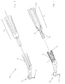
- FIG. 1 and 2 An example of embodiment of an operating unit and of a device for implantology carried out according to the invention are shown in Figures 1 and 2 , where they are indicated as a whole by 1 and 100, respectively.
- the device 100 comprises the operating unit 1 that is equipped with actuator means suited to transmit the motion generated manually by the user to the tool U.
- said actuator means comprise a handle or handgrip 2 suited to be grasped and set rotating by the user.
- the handgrip 2 is integral with one end of a transmission shaft 3 provided, at the other end, with fastening means 4 suited to fasten the replaceable rotary tool U.
- the shaft 3 is positioned on bearings 3a and housed into a casing or handpiece 5 in which it is possible to identify at least one gripping area 5a for the user.
- the operating unit 1 and the device 100 proposed herein use the force generated by the user to set the tool U in motion and therefore they do not need a power or feeding unit for their operation.
- the power unit of the device is constituted by the hand of the user that acts directly on the handgrip 2.
- the tool U it is constituted by a dental file or a rotating tip that is applied to the fastening means 4 comprising a tool-carrier head with rapid coupling.
- a first example, not represented herein for the sake of brevity, is differentiated from the previous one due to the fact that it is also provided with means suited to lock the transmission shaft 3 and/or the handgrip 2.
- Said locking means which can be selectively activated by the user and comprise, for example, a ratchet system, advantageously allow the device to be transformed into a useful tool that can be grasped by the user to tighten or loosen, for example, the screws that make up the implant itself.
- a further example indicated as a whole by 101 in Figures 3 and 4 is differentiated from the previous one due to the fact that the operating unit 1a is removably connected to the handpiece 5 of the device 101.
- the operating unit 1a comprises a driving shaft 6, visible in Figure 4 , integral with the handgrip 2a and provided with first coupling members 7a cooperating with second coupling members 7b integral with a driven shaft 8 that transmits the rotary motion to the tool U.
- said coupling members 7a, 7b comprise a self-centering joint with rapid coupling, of the male-female type, whose parts are integral with the driving shaft 6 and the driven shaft 8, respectively.
- the first coupling members 7a are compatible with the corresponding coupling members with which the known handpieces described above are provided.
- a further embodiment of the invention not represented herein is differentiated from the previous ones due to the fact that it comprises replaceable mechanical interface means, suited to be interposed between the first and second coupling members 7a, 7b.
- FIG. 1b and 102 An embodiment of the operating unit and of the device carried out according to the invention, indicated by 1b and 102, respectively, in Figures 5 and 6 , is differentiated from the previous one due to the fact that the actuator means comprise a ratchet system that cooperates with the driving shaft 6 and can be operated by the user by means of a button 10.
- the actuator means comprise a ratchet system that cooperates with the driving shaft 6 and can be operated by the user by means of a button 10.
- the rotation of the tool U is obtained by the user by exerting a pressure P on the button 10 that, through the above mentioned mechanical members, transforms the motion into the rotation of the tool U.
- said mechanical members comprise, as explained above, a ratchet system with elastic return, provided with a gear wheel 11 integral with the driving shaft 6 and a pawl and/or rack that are not visible.
- a further embodiment of the invention is differentiated from the previous one due to the fact that between the driving shaft 6 and the driven shaft 8 there is a reduction unit suited to change the ratio between the rotation speed of the two shafts and thus between the speed of the tool U and the movement transmitted by the user through the actuator means.
- the user who is usually a doctor, after identifying the area where the support structure must be implanted, chooses the tool U that is most suitable for the operation to be carried out.
- the he/she applies the tool U, usually a dental file, to the tool-carrier head 4 and grasps the device 100, as shown in Figure 1 .
- the embodiment proposed herein ensures a direct and sensitive control of the cutting tool, thus reducing the stress of the dentist that is going to operate.
Landscapes
- Health & Medical Sciences (AREA)
- Oral & Maxillofacial Surgery (AREA)
- Dentistry (AREA)
- Epidemiology (AREA)
- Life Sciences & Earth Sciences (AREA)
- Animal Behavior & Ethology (AREA)
- General Health & Medical Sciences (AREA)
- Public Health (AREA)
- Veterinary Medicine (AREA)
- Dental Tools And Instruments Or Auxiliary Dental Instruments (AREA)
- Instructional Devices (AREA)
Claims (14)
- Unité d'actionnement (1, 1a, 1b, 1c) indiquée pour être reliée à un outil pivotant (U) pour utilisation dentaire, ladite unité comprenant des moyens actionneurs aptes à être reliés audit outil (U) pour transmettre le mouvement généré manuellement par l'utilisateur audit outil (U),
caractérisée en ce que lesdits moyens actionneurs comprennent un système à cliquet indiqué pour être actionné par l'utilisateur au moyen d'un bouton (10), de façon à ce que la pression exercée par l'utilisateur sur ledit bouton (10) donne comme résultat la rotation dudit outil (U). - Unité selon la revendication 1), caractérisée en ce que ledit système à cliquet est du type à retour élastique de façon à ce qu'une fois que ledit bouton a atteint la fin de sa course il revient à sa position initiale.
- Unité selon l'une des revendications précédentes, caractérisée en ce qu'il comprend un arbre de commande (6) indiqué pour être pivoté par une roue dentée (11) apte à être actionnée par l'utilisateur au moyen dudit bouton (1d), ledit arbre de commande (6) comprenant de premiers éléments d'accouplement (7a) indiqués pour être accouplés avec de seconds éléments d'accouplement (7b) solidaires d'un arbre entraîné (8) d'une pièce à main doté dudit outil (U).
- Unité selon la revendication 3), caractérisée en ce que lesdits éléments d'accouplement (7a, 7b) comprennent un joint à raccord rapide.
- Unité selon la revendication 3) ou 4), caractérisée en ce qu'elle comprend un groupe réducteur interposé entre lesdits moyens actionneurs et ledit arbre entraîné (8), apte à varier le rapport entre la vitesse de rotation desdits arbres.
- Unité selon l'une quelconque des revendications précédentes, caractérisée en ce qu'elle comprend également une unité d'embrayage (15) indiquée pour contrôler le couple maximum qui peut être appliqué audit outil (U) par l'utilisateur.
- Dispositif (100, 101, 102, 103) pour utilisation dentaire, comprenant une pièce à main (5) dotée de moyens de fixation (4) d'un outil (u) et une unité d'actionnement (1, 1a, 1b, 1c) dudit outil, caractérisé en ce que ladite unité d'actionnement est réalisée selon l'une quelconque des revendications précédentes, et en ce que lesdits moyens actionneurs sont reliés mécaniquement audit outil (U) de façon à transmettre le mouvement généré manuellement par l'utilisateur audit outil.
- Dispositif selon la revendication 7), caractérisé en ce qu'il comprend également des moyens de blocage qui peuvent être actionnés sélectivement par l'utilisateur et sont indiqués pour bloquer la rotation dudit outil.
- Dispositif selon la revendication 8), caractérisé en ce que lesdits moyens de blocage agissent sur lesdits moyens actionneurs.
- Dispositif selon la revendication 7), 8) ou 9), caractérisé en ce que ladite unité d'actionnement (1b) est associée de manière amovible avec ladite pièce à main (5).
- Dispositif selon les revendications 3) et 10) ou 4) et 10), caractérisé en ce qu'il comprend des moyens d'interface mécaniques remplaçables indiqués pour être interposés entre lesdits premiers et lesdits seconds éléments d'accouplement (7a, 7b).
- Dispositif selon l'une quelconque des revendications de 7) à 11), caractérisé en ce que ladite pièce à main comprend au moins une zone de prise (5a) pour l'utilisateur.
- Dispositif selon l'une quelconque des revendications de 7) à 12), caractérisé en ce que lesdits moyens de fixation (4) comprennent une tête porte-outils.
- Dispositif selon l'une quelconque des revendications de 7) à 13), caractérisé en ce que ladite pièce à main comprend également un groupe réducteur indiqué pour varier le rapport entre la vitesse de rotation dudit outil et le mouvement transmis auxdits moyens actionneurs par ledit utilisateur.
Applications Claiming Priority (2)
| Application Number | Priority Date | Filing Date | Title |
|---|---|---|---|
| IT000044A ITVI20050044A1 (it) | 2005-02-16 | 2005-02-16 | Gruppo di azionamento di un utensile odontoiatrico e dispositivo per uso odontoiatrico |
| PCT/IB2006/000236 WO2006087614A1 (fr) | 2005-02-16 | 2006-02-08 | Unite de production d'outils dentaires et dispositif a usage dentaire |
Publications (2)
| Publication Number | Publication Date |
|---|---|
| EP1848362A1 EP1848362A1 (fr) | 2007-10-31 |
| EP1848362B1 true EP1848362B1 (fr) | 2011-07-20 |
Family
ID=36118069
Family Applications (1)
| Application Number | Title | Priority Date | Filing Date |
|---|---|---|---|
| EP06710334A Expired - Lifetime EP1848362B1 (fr) | 2005-02-16 | 2006-02-08 | Unite d'operation d'outils dentaires et dispositif a usage dentaire |
Country Status (5)
| Country | Link |
|---|---|
| EP (1) | EP1848362B1 (fr) |
| AT (1) | ATE516765T1 (fr) |
| IT (1) | ITVI20050044A1 (fr) |
| PT (1) | PT1848362E (fr) |
| WO (1) | WO2006087614A1 (fr) |
Families Citing this family (1)
| Publication number | Priority date | Publication date | Assignee | Title |
|---|---|---|---|---|
| IT202400005449A1 (it) * | 2024-03-12 | 2025-09-12 | Alfredo NATALI | Utensile odontoiatrico |
Family Cites Families (5)
| Publication number | Priority date | Publication date | Assignee | Title |
|---|---|---|---|---|
| US1356352A (en) * | 1920-05-01 | 1920-10-19 | Gonzalez Feliciano | Dental tool |
| DE8607407U1 (de) * | 1986-03-18 | 1986-05-07 | Gebr. Wagschal GmbH & Co KG, 2804 Lilienthal | Eindrehinstrument zum Eindrehen von Zahnimplantaten |
| JP2803030B2 (ja) * | 1995-12-28 | 1998-09-24 | 株式会社ナカニシ | ハンドトルクドライバー |
| KR100354125B1 (ko) * | 2000-04-06 | 2002-09-28 | 장상건 | 치과용 매뉴얼 핸드래치리머 |
| US6957959B2 (en) * | 2002-06-04 | 2005-10-25 | Zimmer Dental, Inc. | Dental hand tool with ratchet mechanism |
-
2005
- 2005-02-16 IT IT000044A patent/ITVI20050044A1/it unknown
-
2006
- 2006-02-08 AT AT06710334T patent/ATE516765T1/de not_active IP Right Cessation
- 2006-02-08 EP EP06710334A patent/EP1848362B1/fr not_active Expired - Lifetime
- 2006-02-08 WO PCT/IB2006/000236 patent/WO2006087614A1/fr not_active Ceased
- 2006-02-08 PT PT06710334T patent/PT1848362E/pt unknown
Also Published As
| Publication number | Publication date |
|---|---|
| EP1848362A1 (fr) | 2007-10-31 |
| ITVI20050044A1 (it) | 2006-08-17 |
| ATE516765T1 (de) | 2011-08-15 |
| PT1848362E (pt) | 2011-10-07 |
| WO2006087614A1 (fr) | 2006-08-24 |
Similar Documents
| Publication | Publication Date | Title |
|---|---|---|
| EP1128777B1 (fr) | Instrument dentaire revetu de carbone sous forme de diamant | |
| US6322566B1 (en) | Intraoral distractor for callus distraction in the lower jaw | |
| US7547210B1 (en) | Universal, multifunctional, single unit, rotary osteotome | |
| EP2578183A1 (fr) | Dispositif pour relâcher, insérer et retirer des implants dentaires | |
| EP0962192B8 (fr) | Instrument médical ou dentaire, destiné à couper des tissue corporels ainsi que son outil | |
| KR101068462B1 (ko) | 각도조절이 자유로운 치과용 수동핸드피스 | |
| EP1558155A1 (fr) | Dispositif extenseur osteogene radial | |
| EP1302173B1 (fr) | Unité dentaire | |
| EP2134288B1 (fr) | Dispositif ultrasonore de retrait de couronnes et de bridges | |
| US10034723B2 (en) | Tooth bracket extraction device and methods for extracting a bracket section from teeth | |
| WO2006087614A1 (fr) | Unite de production d'outils dentaires et dispositif a usage dentaire | |
| EP3361984A1 (fr) | Dispositif de perçage chirurgical à contre-angle pour la découpe d'un os, empêchant des lésions dans les tissus mous | |
| KR100893787B1 (ko) | 핸드 콘트라앵글 마이크로임플란트 토크 드라이버 | |
| JP2020081828A (ja) | 往復駆動式根管充填具 | |
| KR20150000629U (ko) | 임플란트 시술용 드라이버 | |
| KR102357361B1 (ko) | 치주인대 박리용 덴탈 해머기구 | |
| US20150037755A1 (en) | Dental Extraction Burs for Extraction of a tooth or a portion of a Tooth | |
| EP1547565A2 (fr) | Unité dentaire | |
| EP3545899A1 (fr) | Pince pour l'extraction de dents et de racines dentaires restantes | |
| US20240197451A1 (en) | Device for screwing in dental implants | |
| KR200448454Y1 (ko) | 착탈가능한 치과용 임플란트 핸드피스의 몸체 | |
| Devi et al. | Piezosurgery in Periodontics | |
| EP1815816B1 (fr) | Appareil auxiliaire pour traitements dentaires | |
| JP3538161B2 (ja) | 歯科インプラント手術装置 | |
| CN212661982U (zh) | 一种口腔种植修复牙用的电动螺丝刀 |
Legal Events
| Date | Code | Title | Description |
|---|---|---|---|
| PUAI | Public reference made under article 153(3) epc to a published international application that has entered the european phase |
Free format text: ORIGINAL CODE: 0009012 |
|
| 17P | Request for examination filed |
Effective date: 20070806 |
|
| AK | Designated contracting states |
Kind code of ref document: A1 Designated state(s): AT BE BG CH CY CZ DE DK EE ES FI FR GB GR HU IE IS IT LI LT LU LV MC NL PL PT RO SE SI SK TR |
|
| DAX | Request for extension of the european patent (deleted) | ||
| GRAP | Despatch of communication of intention to grant a patent |
Free format text: ORIGINAL CODE: EPIDOSNIGR1 |
|
| GRAS | Grant fee paid |
Free format text: ORIGINAL CODE: EPIDOSNIGR3 |
|
| GRAA | (expected) grant |
Free format text: ORIGINAL CODE: 0009210 |
|
| AK | Designated contracting states |
Kind code of ref document: B1 Designated state(s): AT BE BG CH CY CZ DE DK EE ES FI FR GB GR HU IE IS IT LI LT LU LV MC NL PL PT RO SE SI SK TR |
|
| REG | Reference to a national code |
Ref country code: GB Ref legal event code: FG4D |
|
| REG | Reference to a national code |
Ref country code: CH Ref legal event code: EP |
|
| REG | Reference to a national code |
Ref country code: DE Ref legal event code: R096 Ref document number: 602006023165 Country of ref document: DE Effective date: 20110922 |
|
| REG | Reference to a national code |
Ref country code: PT Ref legal event code: SC4A Free format text: AVAILABILITY OF NATIONAL TRANSLATION Effective date: 20110929 |
|
| REG | Reference to a national code |
Ref country code: RO Ref legal event code: EPE |
|
| REG | Reference to a national code |
Ref country code: NL Ref legal event code: VDEP Effective date: 20110720 |
|
| REG | Reference to a national code |
Ref country code: AT Ref legal event code: MK05 Ref document number: 516765 Country of ref document: AT Kind code of ref document: T Effective date: 20110720 |
|
| PG25 | Lapsed in a contracting state [announced via postgrant information from national office to epo] |
Ref country code: BE Free format text: LAPSE BECAUSE OF FAILURE TO SUBMIT A TRANSLATION OF THE DESCRIPTION OR TO PAY THE FEE WITHIN THE PRESCRIBED TIME-LIMIT Effective date: 20110720 Ref country code: IS Free format text: LAPSE BECAUSE OF FAILURE TO SUBMIT A TRANSLATION OF THE DESCRIPTION OR TO PAY THE FEE WITHIN THE PRESCRIBED TIME-LIMIT Effective date: 20111120 Ref country code: SE Free format text: LAPSE BECAUSE OF FAILURE TO SUBMIT A TRANSLATION OF THE DESCRIPTION OR TO PAY THE FEE WITHIN THE PRESCRIBED TIME-LIMIT Effective date: 20110720 Ref country code: FI Free format text: LAPSE BECAUSE OF FAILURE TO SUBMIT A TRANSLATION OF THE DESCRIPTION OR TO PAY THE FEE WITHIN THE PRESCRIBED TIME-LIMIT Effective date: 20110720 Ref country code: LT Free format text: LAPSE BECAUSE OF FAILURE TO SUBMIT A TRANSLATION OF THE DESCRIPTION OR TO PAY THE FEE WITHIN THE PRESCRIBED TIME-LIMIT Effective date: 20110720 Ref country code: NL Free format text: LAPSE BECAUSE OF FAILURE TO SUBMIT A TRANSLATION OF THE DESCRIPTION OR TO PAY THE FEE WITHIN THE PRESCRIBED TIME-LIMIT Effective date: 20110720 |
|
| PG25 | Lapsed in a contracting state [announced via postgrant information from national office to epo] |
Ref country code: SI Free format text: LAPSE BECAUSE OF FAILURE TO SUBMIT A TRANSLATION OF THE DESCRIPTION OR TO PAY THE FEE WITHIN THE PRESCRIBED TIME-LIMIT Effective date: 20110720 Ref country code: CY Free format text: LAPSE BECAUSE OF FAILURE TO SUBMIT A TRANSLATION OF THE DESCRIPTION OR TO PAY THE FEE WITHIN THE PRESCRIBED TIME-LIMIT Effective date: 20110720 Ref country code: AT Free format text: LAPSE BECAUSE OF FAILURE TO SUBMIT A TRANSLATION OF THE DESCRIPTION OR TO PAY THE FEE WITHIN THE PRESCRIBED TIME-LIMIT Effective date: 20110720 Ref country code: PL Free format text: LAPSE BECAUSE OF FAILURE TO SUBMIT A TRANSLATION OF THE DESCRIPTION OR TO PAY THE FEE WITHIN THE PRESCRIBED TIME-LIMIT Effective date: 20110720 Ref country code: GR Free format text: LAPSE BECAUSE OF FAILURE TO SUBMIT A TRANSLATION OF THE DESCRIPTION OR TO PAY THE FEE WITHIN THE PRESCRIBED TIME-LIMIT Effective date: 20111021 Ref country code: LV Free format text: LAPSE BECAUSE OF FAILURE TO SUBMIT A TRANSLATION OF THE DESCRIPTION OR TO PAY THE FEE WITHIN THE PRESCRIBED TIME-LIMIT Effective date: 20110720 |
|
| PG25 | Lapsed in a contracting state [announced via postgrant information from national office to epo] |
Ref country code: SK Free format text: LAPSE BECAUSE OF FAILURE TO SUBMIT A TRANSLATION OF THE DESCRIPTION OR TO PAY THE FEE WITHIN THE PRESCRIBED TIME-LIMIT Effective date: 20110720 Ref country code: CZ Free format text: LAPSE BECAUSE OF FAILURE TO SUBMIT A TRANSLATION OF THE DESCRIPTION OR TO PAY THE FEE WITHIN THE PRESCRIBED TIME-LIMIT Effective date: 20110720 |
|
| PLBE | No opposition filed within time limit |
Free format text: ORIGINAL CODE: 0009261 |
|
| STAA | Information on the status of an ep patent application or granted ep patent |
Free format text: STATUS: NO OPPOSITION FILED WITHIN TIME LIMIT |
|
| PG25 | Lapsed in a contracting state [announced via postgrant information from national office to epo] |
Ref country code: EE Free format text: LAPSE BECAUSE OF FAILURE TO SUBMIT A TRANSLATION OF THE DESCRIPTION OR TO PAY THE FEE WITHIN THE PRESCRIBED TIME-LIMIT Effective date: 20110720 |
|
| 26N | No opposition filed |
Effective date: 20120423 |
|
| PG25 | Lapsed in a contracting state [announced via postgrant information from national office to epo] |
Ref country code: DK Free format text: LAPSE BECAUSE OF FAILURE TO SUBMIT A TRANSLATION OF THE DESCRIPTION OR TO PAY THE FEE WITHIN THE PRESCRIBED TIME-LIMIT Effective date: 20110720 |
|
| REG | Reference to a national code |
Ref country code: DE Ref legal event code: R097 Ref document number: 602006023165 Country of ref document: DE Effective date: 20120423 |
|
| PG25 | Lapsed in a contracting state [announced via postgrant information from national office to epo] |
Ref country code: MC Free format text: LAPSE BECAUSE OF NON-PAYMENT OF DUE FEES Effective date: 20120229 |
|
| REG | Reference to a national code |
Ref country code: CH Ref legal event code: PL |
|
| GBPC | Gb: european patent ceased through non-payment of renewal fee |
Effective date: 20120208 |
|
| PG25 | Lapsed in a contracting state [announced via postgrant information from national office to epo] |
Ref country code: CH Free format text: LAPSE BECAUSE OF NON-PAYMENT OF DUE FEES Effective date: 20120229 Ref country code: LI Free format text: LAPSE BECAUSE OF NON-PAYMENT OF DUE FEES Effective date: 20120229 |
|
| REG | Reference to a national code |
Ref country code: IE Ref legal event code: MM4A |
|
| REG | Reference to a national code |
Ref country code: FR Ref legal event code: ST Effective date: 20121031 |
|
| REG | Reference to a national code |
Ref country code: DE Ref legal event code: R119 Ref document number: 602006023165 Country of ref document: DE Effective date: 20120901 |
|
| PG25 | Lapsed in a contracting state [announced via postgrant information from national office to epo] |
Ref country code: FR Free format text: LAPSE BECAUSE OF NON-PAYMENT OF DUE FEES Effective date: 20120229 Ref country code: IE Free format text: LAPSE BECAUSE OF NON-PAYMENT OF DUE FEES Effective date: 20120208 Ref country code: GB Free format text: LAPSE BECAUSE OF NON-PAYMENT OF DUE FEES Effective date: 20120208 |
|
| PG25 | Lapsed in a contracting state [announced via postgrant information from national office to epo] |
Ref country code: ES Free format text: LAPSE BECAUSE OF FAILURE TO SUBMIT A TRANSLATION OF THE DESCRIPTION OR TO PAY THE FEE WITHIN THE PRESCRIBED TIME-LIMIT Effective date: 20111031 |
|
| PG25 | Lapsed in a contracting state [announced via postgrant information from national office to epo] |
Ref country code: DE Free format text: LAPSE BECAUSE OF NON-PAYMENT OF DUE FEES Effective date: 20120901 Ref country code: BG Free format text: LAPSE BECAUSE OF FAILURE TO SUBMIT A TRANSLATION OF THE DESCRIPTION OR TO PAY THE FEE WITHIN THE PRESCRIBED TIME-LIMIT Effective date: 20111020 |
|
| PG25 | Lapsed in a contracting state [announced via postgrant information from national office to epo] |
Ref country code: TR Free format text: LAPSE BECAUSE OF FAILURE TO SUBMIT A TRANSLATION OF THE DESCRIPTION OR TO PAY THE FEE WITHIN THE PRESCRIBED TIME-LIMIT Effective date: 20110720 |
|
| PG25 | Lapsed in a contracting state [announced via postgrant information from national office to epo] |
Ref country code: LU Free format text: LAPSE BECAUSE OF NON-PAYMENT OF DUE FEES Effective date: 20120208 |
|
| PG25 | Lapsed in a contracting state [announced via postgrant information from national office to epo] |
Ref country code: HU Free format text: LAPSE BECAUSE OF FAILURE TO SUBMIT A TRANSLATION OF THE DESCRIPTION OR TO PAY THE FEE WITHIN THE PRESCRIBED TIME-LIMIT Effective date: 20060208 |
|
| PGFP | Annual fee paid to national office [announced via postgrant information from national office to epo] |
Ref country code: RO Payment date: 20200129 Year of fee payment: 15 Ref country code: PT Payment date: 20200212 Year of fee payment: 15 |
|
| PGFP | Annual fee paid to national office [announced via postgrant information from national office to epo] |
Ref country code: IT Payment date: 20210203 Year of fee payment: 16 |
|
| PG25 | Lapsed in a contracting state [announced via postgrant information from national office to epo] |
Ref country code: PT Free format text: LAPSE BECAUSE OF NON-PAYMENT OF DUE FEES Effective date: 20210809 Ref country code: RO Free format text: LAPSE BECAUSE OF NON-PAYMENT OF DUE FEES Effective date: 20210208 |
|
| PG25 | Lapsed in a contracting state [announced via postgrant information from national office to epo] |
Ref country code: IT Free format text: LAPSE BECAUSE OF NON-PAYMENT OF DUE FEES Effective date: 20220208 |