EP1848632B1 - Compartiment a bagages pour avion - Google Patents
Compartiment a bagages pour avion Download PDFInfo
- Publication number
- EP1848632B1 EP1848632B1 EP06706972A EP06706972A EP1848632B1 EP 1848632 B1 EP1848632 B1 EP 1848632B1 EP 06706972 A EP06706972 A EP 06706972A EP 06706972 A EP06706972 A EP 06706972A EP 1848632 B1 EP1848632 B1 EP 1848632B1
- Authority
- EP
- European Patent Office
- Prior art keywords
- locking device
- luggage compartment
- flap
- tilting floor
- tilting
- Prior art date
- Legal status (The legal status is an assumption and is not a legal conclusion. Google has not performed a legal analysis and makes no representation as to the accuracy of the status listed.)
- Ceased
Links
- 230000008878 coupling Effects 0.000 claims description 27
- 238000010168 coupling process Methods 0.000 claims description 27
- 238000005859 coupling reaction Methods 0.000 claims description 27
- 239000000725 suspension Substances 0.000 claims description 21
- 238000000034 method Methods 0.000 claims description 9
- 230000005484 gravity Effects 0.000 claims description 7
- 230000001133 acceleration Effects 0.000 claims description 4
- 230000000284 resting effect Effects 0.000 claims description 3
- 230000002441 reversible effect Effects 0.000 claims description 3
- 230000007246 mechanism Effects 0.000 description 10
- 230000001965 increasing effect Effects 0.000 description 3
- 230000002708 enhancing effect Effects 0.000 description 2
- 238000009434 installation Methods 0.000 description 2
- 230000036961 partial effect Effects 0.000 description 2
- 230000008569 process Effects 0.000 description 2
- 208000027418 Wounds and injury Diseases 0.000 description 1
- 230000008901 benefit Effects 0.000 description 1
- 230000006378 damage Effects 0.000 description 1
- 230000000694 effects Effects 0.000 description 1
- 208000014674 injury Diseases 0.000 description 1
- 230000000670 limiting effect Effects 0.000 description 1
- 230000009467 reduction Effects 0.000 description 1
- 230000002829 reductive effect Effects 0.000 description 1
Images



Classifications
-
- B—PERFORMING OPERATIONS; TRANSPORTING
- B64—AIRCRAFT; AVIATION; COSMONAUTICS
- B64D—EQUIPMENT FOR FITTING IN OR TO AIRCRAFT; FLIGHT SUITS; PARACHUTES; ARRANGEMENT OR MOUNTING OF POWER PLANTS OR PROPULSION TRANSMISSIONS IN AIRCRAFT
- B64D11/00—Passenger or crew accommodation; Flight-deck installations not otherwise provided for
- B64D11/003—Stowage devices for passengers' personal luggage
Definitions
- This invention relates to luggage compartments for aircraft.
- this invention relates to a luggage compartment for an aircraft, an aircraft comprising such a luggage compartment, the use of a luggage compartment in an aircraft, and a method for loading baggage in a luggage compartment.
- Luggage compartments in aircraft are used for stowing and keeping carryon baggage, clothing and the like.
- the luggage compartments are located to the left and right of the aisle at or slightly above passenger head level. Since the luggage compartments cannot be suspended so high as to make smaller individuals no longer able to stow baggage in the luggage compartment, larger individuals most often find it impossible to stand up straight under such a luggage compartment.
- US 2002/101090 A1 discloses a pull-down stowage bin assembly including a frame, a bin coupled to the frame for reciprocative movement between an open position and a stowed position, and a restraint assembly to restrain objects located within the bin when the bin is in the open position.
- It is an object of the present invention is to provide for improved baggage stowage in aircraft.
- a luggage compartment for aircraft comprising a tilting floor, a flap and a pivoted suspension device, wherein the flap has an open and closed position, and wherein the tilting floor is adapted to rotate around the suspension device from an initial position into a loading position with the flap in the open position.
- This configuration of the luggage compartment may ensure that the luggage compartment can be suspended high enough that even large individuals can stand up straight underneath it on the one hand, while also providing for a lower stowing edge height on the other hand, so that smaller individuals can load the luggage compartment without exertion.
- This is enabled by a tilting mechanism that enables the luggage compartment to be fixed high enough horizontally in its initial position, and tilt in its loading position, so that the front edge of the tilting floor is tilted down, also enabling smaller people to conveniently stow items away.
- the tilting floor and suspension device may only be turned if the flap is in the open position. This means that the tilting floor cannot tilt with the flam closed. As a result, the tilting floor is fixed securely in its initial position during normal flight operation, and can only be tilted down accordingly after the flap has been opened.
- the luggage compartment comprises a first locking device, wherein the first locking device can be used to prevent the tilting floor from turning around the suspension device, and wherein the first locking device can be released to allow the tilting floor to turn around the suspension device.
- the first locking device can be locked into the initial position automatically by turning the tilting floor.
- the luggage compartment has a second locking device, wherein the flap can beheld in the closed position by the second locking device, and wherein the second locking device can be released, making it possible to open the flap.
- the luggage compartment also comprises a coupling device for coupling the first locking device with the second locking device, wherein the coupling device is adapted in such a way that the first locking device can only be released once the second locking device has been released, and wherein the coupling device is further designed in such a way that the second locking device can only be closed once the first locking device has been closed.
- the coupling means makes it possible to lock the flap only once the tilting floor has been flipped back into its initial position. This ensures that users always first flip back the tilting floor before closing the flap. This can also help avoid the risk of an accident owing to falling carryon baggage.
- the coupling device comprises a handle, wherein the handle has a first position, a second position and a third position, which can be assumed one after the other.
- the first position here corresponds to the handle in the resting position.
- the second position involves releasing the second locking device of the flap, so that the flap can be opened, and the third position involves releasing the first locking device, so that the luggage compartment can be turned around the suspension device.
- the first and second locking devices may be released one after the other using the same handle in the correct sequence.
- the user pulls on the handle, and as soon as the handle is in the second position, the flap is unlocked.
- the tilting floor is released, and can turn around its suspension axis.
- the suspension device is situated near a line that runs vertically through the center of gravity of the luggage compartment in the initial position, so that only a slight torque is required for turning the tilting floor.
- the suspension device encompasses a rotational axis, wherein the tilting floor has a first lateral wall and a second lateral wall, and wherein the rotational axis rigidly joins the first and second lateral wall, so that the forward and reverse forces, e.g., those produced by aircraft accelerations, can be absorbed by the combination of first lateral wall, second lateral wall and rotational axis.
- Coupling both lateral walls via the rotational axis may provide for a stable combination, which can also absorb strong acceleration forces, e.g., of the kind that may arise during a crash.
- the luggage compartment also has a spring arrangement, wherein a minimum threshold force, which is necessary for turning the tilting floor, can be set via the spring arrangement.
- the spring arrangement may make it possible to set a force that the user must exert to move the tilting floor out of its initial position, for example.
- the spring arrangement can dampen or provide support.
- Another exemplary embodiment of this invention provides for a simple and reliable method with which the luggage compartment may be actuated on board an aircraft.
- the method here comprises the release of a second locking device for opening a flap of the luggage compartment, the release of a first locking device for turning a tilting floor of the luggage compartment from an initial position into a loading position, the loading of baggage into the luggage compartment, the application of a threshold force to turn the tilting floor back into the initial position, the closing of the first locking device for locking the tilting floor, the closing of the flap, and the closing of the second locking device for locking the flap.
- the method according to the invention may make it possible to load or even unload the luggage compartment while the floor still remains horizontally locked upon actuation of the second locking device for opening the flap. Only when a second locking device is additional actuated can the tilting floor be turned into the desired loading/unloading position.
- the corresponding loading/unloading position of the front edge of the tilting floor is here located under the initial position owing to the rotation. This simplifies the loading process.
- the tilting floor can then be turned back, whereupon the flap can only be closed and locked after the initial position has been reached.
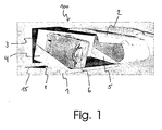
- Fig. 1 shows a first perspective, diagrammatic view of a luggage compartment according to an exemplary embodiment of this invention.
- the luggage compartment 100 according to the invention has a tilting floor 1 with a first lateral wall 4 and a second lateral wall 5.
- the two lateral walls 4, 5 are rigidly joined by way of a rotational axis (not shown on Fig. 1 ), which is located in the floor 1, for example.
- the rotational axis is part of a suspension device 8, which is designed for turning the tilting floor 1, and consequently pivoted (e.g., in corresponding side panels).
- the rotational axis rigidly joins the first and second lateral wall, thereby yielding a stable structure that is able to withstand strong forward and reverse accelerations of the kind that might arise when an aircraft crashes, for example.
- a strong braking effect for example, corresponding forces conveyed by the carryon baggage 6 to the second lateral wall 5 can here be partially deflected to the first lateral wall 4 via the rotational axis. This results in an elevated stability for the luggage compartment.
- the luggage compartment according to the invention encompasses a flap 2, which, as shown on Fig. 1 , can assume an open position.
- the flap 2 can also assume a closed position, in which it can be locked.
- the tilting floor 1 can be turned from an initial position after opening the flap 2 into a loading/unloading position (as shown on Fig. 1 ). In this loading position, carryon baggage can be comfortably loaded and unloaded, since the loading edge (front side) of the tilting floor is lowered.
- the tilting floor 1 also comprises a rear wall 3, which limits the luggage compartment from below.
- Fig. 2 shows a diagrammatic cross sectional view of a luggage compartment arrangement.
- Reference number 200 here denotes a conventional luggage compartment, while reference number 100 denotes a luggage compartment according to this invention.
- a luggage rack in a wide-bodied aircraft is determined by three criteria, specifically a defined stowage volume, an installation height (headroom/standing height) and a loading edge height.
- the standing height or headroom 10 in the luggage compartment 100 with the tilting floor according to the invention is increased relative to the headroom 9 for the known luggage compartment 200.
- the increased headroom measures 6 to 10 cm, for example, but can also be higher (e.g., depending on the maximum tilting angle ⁇ ). This also allows taller people to stand under the luggage compartment without hunching over. This increases passenger comfort significantly.
- the loading edge height 12 of the tilting floor luggage compartment arrangement 10 according to the invention is reduced in the invention relative to the loading edge height 11 of the conventional luggage compartment 200.
- the reduction can here measure several centimeters depending on the position of the bearing arrangement 8 the installation height of the luggage compartment 100 and the maximum tilting angle ⁇ .
- the loading edge height 12 does not wander upward regardless of the elevated suspension of the luggage compartment, but rather (as compared with the conventional solution 200) even migrates downward, as denoted by reference number 13. This further enables a comfortable loading.
- Actuating the lock 7 initially opens the flap 2, while the floor still remains horizontally locked. Only when the lock 7 is again actuated and given a downward pulling motion does the floor tilt into the desired loading/unloading position.
- This threshold force can be generated, for example, by having a portion of the loading weight lie behind the fulcrum, but can also be provided by means of a dampening spring.
- a dampening spring can be provided for heavy carryon baggage to support a rotating motion of the tilting floor. Further, the spring arrangement can be used to set a minimum required threshold force for turning the tilting floor (dead center).
- the flap can only be closed once the tilting floor has returned to the automatically locked initial position. This can simultaneously serve as a safety check, since a closed flap tells the flight personnel that the tilting floor is correctly locked.
- a coupling means that couples a first locking device for locking the tilting floor with a second locking device for locking the flap.
- the coupling means can involve a toothed belt linkage between the two locking mechanisms, so that the first locking device can only be released once the second locking device has been released.
- the coupling means can be designed in such a way that the second locking device can only be closed once the first locking device has been closed.
- the locking device for locking the floor and the locking device for locking the flap may not be coupled.
- the locking device for locking the flap may be adapted as a normal locking mechanism for the flap.
- the other locking device for the tilting floor
- the other locking device for the tilting floor
- the other locking device for the tilting floor
- the first locking device can be locked automatically by turning the tilting floor into the initial position. For example, this can be done using a snapping mechanism or the like, which automatically snaps into a corresponding counterpart once the initial position has been reached, thereby locking the tilting floor. If the tilting floor is then locked, the coupling means release the second locking device (for the flap 2).
- the coupling means here encompass a handle or tongue 7, for example, which can assume three different sequential positions.
- the first position is here the resting position. Actuating the handle makes it possible to bring the handle into a second position, which releases the second locking device of the flap 2. Further moving the handle 7 then brings the handle into a third position, which releases the first locking device of the tilting floor, so that the tilting floor can now be turned into its loading position.
- the turning motion of the tilting floor can be supported or dampened via corresponding pneumatic springs, for example.
- pneumatic springs or another corresponding spring or dampening means
- the spring means can be adjustable, so that the threshold force can be set correspondingly, and hence is independent of the loaded status of the luggage compartment, for example.
- suspending the luggage compartment as described in the invention created a free space 14 that can be used, for example, for a passenger service unit channel (PSU channel).
- PSU channel passenger service unit channel
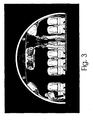
- Fig. 3 shows a diagrammatic cross sectional view of a luggage compartment arrangement in an aircraft fuselage.
- the swivel-mounted tilting floor arrangement can be comfortably flipped down for loading or unloading carryon baggage. This increases passenger comfort, for example, by increasing the headroom under the flipped-up luggage compartments.
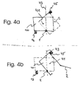
- Fig. 4a-4b show diagrammatic cross sectional views of a luggage compartment arrangement according to an exemplary embodiment of this invention.
- the luggage compartment 100 with tilting floor according to the invention has a rotating suspension device 8, which defines a rotational axis of the luggage compartment 100.
- the center of gravity of the luggage compartment 100 symbolized in its initial position by the continuous lines on Fig. 4a is marked with reference number 41.
- the center of gravity 41 is laterally shifted to the left relative to the line 43 via the fulcrum 8.
- the tilting floor is in a stable position, since the lateral shift in the center of gravity 41 away from the horizontal line 43 causes a torque to act counterclockwise on the tilting floor or luggage compartment 100, which presses the luggage compartment 100 against a fixed stop 46.
- the center of gravity 41 of the luggage compartment 100 in the loading position (shown after having opened the flap 2 and turning the tilting floor or luggage compartment 100 from the initial position on Fig. 4a ) is situated in the end position (see Fig. 4b ) shifted laterally to the right relative to the horizontal axis 43 via the fulcrum 8.
- the tilting floor is in a stable position even in this position, since the torque acts on it clockwise, thereby pressing the tilting floor against the fixed stop 45.
- Mechanically complex and heavy dampening means or force enhancing means can hence be largely omitted.
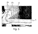
- Fig. 5 shows a diagrammatic partial view of a luggage compartment with a recess 51 on a side panel 50. As evident from Fig. 5 , this prevents the fingers of a user from being jammed when snapping in the tilting floor 1. The risk of injury is minimized as a result.
- a locking device is first released to disengage the flap 2 of the luggage compartment. This makes it possible to open the flap 2.
- a second locking device is released, allowing the tilting floor 1 of the luggage compartment to be tilted from an initial position into a loading position.
- the first and second locking device are here joined with a handle 7 via a coupling means, wherein the coupling means is designed in such a way that the first locking device can only be released once the second locking device has been released, and that the second locking device can only be locked once the first locking device has been closed.
- a threshold force must then be exerted to turn the tilting floor back to the initial position.
- the first locking device automatically latches to lock the tilting floor, and the flap can be closed. After the flap 2 is closed, the flap 2 is automatically locked by a second locking mechanism.
- Fig. 4a there are two stable states in which no restoring force acts.
- the first state is shown on Fig. 4a , in which the acting force actually works counterclockwise, which would cause the tilting element to turn up further if no stop element 46 were provided.
- the second stable position is shown on Fig. 4b , in which the force acts on the tilting element clockwise, so that a tilting motion would continue if a second stop element 45 were not to halt this tilting motion. Therefore, a stable state is also shown on Fig. 4b .
- Torsion dampeners can also be used as the spring arrangement.
- Gaps between the inner lateral walls can be covered by a profile.
- a gap on the rear side of the luggage compartment can be covered by a movable panel (e.g., see 15 on Fig. 1 ).
- the luggage compartment can be unlocked by means of a handle or slide-out tongue, wherein the door is unlocked by about 30% after the tongue is withdrawn, for example, and the tilting floor is unlocked by another 30% while continuing to withdraw the tongue.
- the handle can be designed as a handrail, which the user can use to pull down the tilting floor after withdrawn 60%.
- This handrail can take up the entire width of the luggage compartment, for example.
- the handrail can advantageously encompass a seat or seat row number, which is legible from the both with the tilting floor flipped up or down. Typical forces needed to open or tilt the tilting floor can measure 200 Newtons, for example.
- Fig. 6 shows a diagrammatic view of the actuating principle for the first and second locking devices with coupling means.
- both the first locking device 62 located on the lateral walls of the luggage compartment and the second locking device 61 located on the flap 2 of the luggage compartment are closed in the initial state.
- the two locking devices 61, 62 are coupled together via a coupling means 63 comprising the handle 7.
- the door 2 is unlocked by actuating the handle 7 (shifting from the first position shown on Fig. 6a into the second position shown on Fig. 6b).
- Fig. 6 shows a diagrammatic view of the actuating principle for the first and second locking devices with coupling means.
- FIG. 6c shows how the handle, and hence the coupling means, is moved into the third position via the two locking devices 61, 62, in which the first locking device 62 opens on both sides of the luggage compartment, so that the tilting floor 1 can now be tilted.
- Fig. 6d shows how the handle, and hence the coupling means, is moved into the third position via the two locking devices 61, 62, in which the first locking device 62 opens on both sides of the luggage compartment, so that the tilting floor 1 can now be tilted.
- Fig. 6d shows how the handle, and hence the coupling means, is moved into the third position via the two locking devices 61, 62, in which the first locking device 62 opens on both sides of the luggage compartment, so that the tilting floor 1 can now be tilted.
- the luggage compartment further comprises a frame member 701 or holder which is rotatably attached to the tilting floor and adapted for preventing a piece of luggage to slip out of the compartment when the floor is tilted. For that reason, the frame 701 follows the tilting movement of the floor after the flap is opened, thereby holding back the luggage, as depicted in Fig. 7 .
- the frame member 701 may be rotated upwards in order to access the luggage or to load/unload the compartment.
- the other mechanisms for fixing and/or moving the frame may be used, such as, for example, a sliding mechanism which allows the frame member 701 to be moved upwards when the luggage as to be accessed.
Landscapes
- Engineering & Computer Science (AREA)
- Aviation & Aerospace Engineering (AREA)
- Vehicle Step Arrangements And Article Storage (AREA)
- Closing And Opening Devices For Wings, And Checks For Wings (AREA)
Claims (14)
- Compartiment à bagages pour un avion, le compartiment à bagages comportant :un plancher inclinable (1),un abattant (2),un dispositif de suspension pivotant (8),dans lequel l'abattant a une position ouverte et une position fermée,etdans lequel le plancher inclinable est adapté pour tourner autour du dispositif de suspension depuis une position initiale dans une position de chargement lorsque l'abattant est dans la position ouverte.
- Compartiment à bagages selon la revendication 1, comportant en outre :un premier dispositif de blocage (62),le premier dispositif de blocage étant adapté pour empêcher le plancher inclinable (1) de tourner autour du dispositif de suspension (8), etle premier dispositif de blocage étant adapté pour être libéré afin de permettre au plancher inclinable de tourner autour du dispositif de suspension.
- Compartiment à bagages selon la revendication 2,
dans lequel le premier dispositif de blocage (62) est adapté pour être automatiquement bloqué dans la position initiale en faisant tourner le plancher inclinable. - Compartiment à bagages selon l'une des revendications 1 à 3, comportant en outre :un second dispositif de blocage (61),dans lequel l'abattant est adapté pour être maintenu dans la position fermée par le second dispositif de blocage (61), etdans lequel le second dispositif de blocage est adapté pour être libéré pour permettre à l'abattant (2) de s'ouvrir.
- Compartiment à bagages selon l'une des revendications précédentes, comportant également :un dispositif de couplage (63) pour coupler le premier dispositif de blocage (62) avec le second dispositif de blocage (61),dans lequel le dispositif de couplage (63) est adapté de manière à ce que le premier dispositif de blocage (62) puisse uniquement être libéré une fois que le second dispositif de blocage (61) a été libéré, etdans lequel le dispositif de couplage (63) est également adapté de manière à ce que le second dispositif de blocage (61) puisse uniquement être bloqué une fois que le premier dispositif de blocage (62) est fermé.
- Compartiment à bagages selon la revendication 5,
dans lequel le dispositif de couplage (63) comporte une poignée (7),
dans lequel la poignée (67) a une première position, une deuxième position et une troisième position, dans lequel la poignée (7) est adaptée pour prendre les première, deuxième et troisième positions l'une après l'autre,
dans lequel la première position correspond à une position de repos,
dans lequel la deuxième position implique la libération du second dispositif de blocage de l'abattant (2), de telle sorte que l'abattant peut être ouvert, et
dans lequel la troisième position implique la libération du premier dispositif de blocage (62), de telle sorte que le compartiment à bagages peut tourner autour du dispositif de suspension (8). - Compartiment à bagages selon l'une des revendications précédentes,
dans lequel le dispositif de suspension (8) est situé près d'une ligne qui s'étend verticalement à travers le centre de gravité du compartiment à bagages dans la position initiale, de telle sorte que seul un léger couple est requis pour faire tourner le plancher inclinable (1). - Compartiment à bagages selon l'une des revendications précédentes,
dans lequel le dispositif de suspension (8) comporte un axe de rotation, dans lequel le plancher inclinable comporte une première paroi latérale et une seconde paroi latérale,
dans lequel l'axe de rotation réunit rigidement les première et seconde parois latérales, de telle sorte que des forces avant et des forces arrière produites par des accélérations d'avion peuvent être absorbées par la première paroi latérale, par la seconde paroi latérale et par l'axe de rotation. - Compartiment à bagages selon l'une des revendications précédentes, comportant en outre :un agencement à ressort,dans lequel l'agencement à ressort est adapté pour régler une force de seuil minimale, la force de seuil minimale étant requise pour faire tourner le plancher inclinable (1).
- Compartiment à bagages selon l'une des revendications précédentes, comportant également :un élément de châssis adapté pour empêcher un bagage de glisser à l'extérieur du compartiment à bagages lorsque le plancher inclinable est incliné.
- Avion comportant un compartiment à bagages selon l'une des revendications 1 à 10.
- Utilisation d'un compartiment à bagages selon l'une des revendications 1 à 10 dans un avion.
- Procédé pour actionner un compartiment à bagages à bord d'un avion, le procédé comportant les étapes suivantes consistant à :libérer un second dispositif de blocage (61) pour ouvrir un abattant (2) du compartiment à bagages,libérer un premier dispositif de blocage (62) pour faire tourner un plancher inclinable (1) du compartiment à bagages depuis une position initiale dans la position de chargement,charger un bagage dans le compartiment à bagages,appliquer une force de seuil pour faire tourner le plancher inclinable (1) pour le ramener dans la position initiale,fermer le premier dispositif de blocage (62) pour bloquer le plancher inclinable,fermer l'abattant (2), etfermer le second dispositif de blocage (61) pour bloquer l'abattant (2).
- Procédé selon la revendication 13,
dans lequel le premier dispositif de blocage (62) et le second dispositif de blocage (61) sont réunis à l'aide d'une poignée (7) par des moyens de couplage (63),
dans lequel les moyens de couplage (63) sont adaptés de manière à ce que le premier dispositif de blocage (62) puisse uniquement être libéré une fois que le second dispositif de blocage (61) a été libéré, et
dans lequel les moyens de couplage (63) sont également adaptés de manière à ce que le second dispositif de blocage (61) puisse uniquement être bloqué une fois que le premier dispositif de blocage (62) a été fermé.
Applications Claiming Priority (3)
| Application Number | Priority Date | Filing Date | Title |
|---|---|---|---|
| US65307505P | 2005-02-15 | 2005-02-15 | |
| DE102005006887 | 2005-02-15 | ||
| PCT/EP2006/001370 WO2006087183A1 (fr) | 2005-02-15 | 2006-02-15 | Compartiment a bagages pour avion |
Publications (2)
| Publication Number | Publication Date |
|---|---|
| EP1848632A1 EP1848632A1 (fr) | 2007-10-31 |
| EP1848632B1 true EP1848632B1 (fr) | 2010-04-07 |
Family
ID=36102585
Family Applications (1)
| Application Number | Title | Priority Date | Filing Date |
|---|---|---|---|
| EP06706972A Ceased EP1848632B1 (fr) | 2005-02-15 | 2006-02-15 | Compartiment a bagages pour avion |
Country Status (8)
| Country | Link |
|---|---|
| US (1) | US7823830B2 (fr) |
| EP (1) | EP1848632B1 (fr) |
| JP (1) | JP5020831B2 (fr) |
| BR (1) | BRPI0606444A2 (fr) |
| CA (1) | CA2591947C (fr) |
| DE (1) | DE602006013417D1 (fr) |
| RU (1) | RU2395431C2 (fr) |
| WO (1) | WO2006087183A1 (fr) |
Families Citing this family (22)
| Publication number | Priority date | Publication date | Assignee | Title |
|---|---|---|---|---|
| EP2132088B1 (fr) * | 2007-04-12 | 2016-09-14 | BE Aerospace, Inc. | Soute à bagages en hauteur pour l'intérieur d'un avion |
| DE102007030330B4 (de) * | 2007-06-29 | 2010-07-22 | Airbus Deutschland Gmbh | Schwenkbarer Geräteträger in Kombination mit modifizierter Gepäckablage |
| DE102007059686A1 (de) | 2007-12-12 | 2009-06-18 | Airbus Deutschland Gmbh | Staufachanordnung |
| DE102008006741B4 (de) * | 2008-01-30 | 2014-04-10 | Airbus Operations Gmbh | Lösbares Befestigen einer Komponente in einem Flugzeug |
| DE102008049639A1 (de) * | 2008-09-30 | 2010-04-08 | Airbus Deutschland Gmbh | Lastpfadoptimierte schwenkbare Gepäckablage (Hatrack) |
| DE102008051240B3 (de) | 2008-10-10 | 2010-09-30 | Airbus Deutschland Gmbh | Vorrichtung zur Aufnahme von Gepäck in einer Passagierkabine eines Flugzeuges |
| DE102009014573B4 (de) | 2009-03-24 | 2011-06-01 | Airbus Operations Gmbh | Transformierbares Gepäckstaufach für eine Flugzeugkabine |
| US8262022B2 (en) * | 2009-12-15 | 2012-09-11 | The Boeing Company | Overhead stowage bin load transfer and balance system |
| US8727278B2 (en) * | 2010-07-16 | 2014-05-20 | The Boeing Company | Article retention device |
| DE102011108895A1 (de) * | 2011-07-29 | 2013-01-31 | Airbus Operations Gmbh | Tragende Struktur für bewegliches Staufach |
| US10029794B2 (en) | 2012-02-14 | 2018-07-24 | C&D Zodiac, Inc. | Outboard rotating pivot bin assembly |
| US9789963B2 (en) | 2012-02-14 | 2017-10-17 | C&D Zodiac, Inc. | Pivot bin assembly with minimal force required for closing |
| US9981609B2 (en) * | 2013-01-16 | 2018-05-29 | The Boeing Company | Rotating luggage bin |
| AT513939A1 (de) * | 2013-02-01 | 2014-08-15 | Facc Ag | Überkopf-Gepäckfach für Flugzeuge und Flugzeug mit solchen Überkopf-Gepäckfächern |
| JP6110513B2 (ja) * | 2013-02-13 | 2017-04-05 | シーアンドディー ゾディアック,インコーポレイティド | 回転式棚アセンブリ |
| EP2832642A1 (fr) | 2013-07-31 | 2015-02-04 | Zodiac Aerotechnics | Dispositif de stockage comprenant un compartiment à bagage et une unité d'oxygène d'urgence |
| AT515849A1 (de) * | 2014-05-26 | 2015-12-15 | Facc Ag | Überkopf-Gepäckfach |
| AT516642A1 (de) * | 2014-12-15 | 2016-07-15 | Facc Ag | Elektrisch betätigbares bewegbares Überkopf-Gepäckfach für Flugzeuge |
| CA2973070C (fr) * | 2015-01-30 | 2020-07-21 | C&D Zodiac, Inc. | Ensemble de casiers a pivot necessitant une force minimale pour la fermeture |
| US9738386B2 (en) * | 2015-04-09 | 2017-08-22 | The Boeing Company | Overhead stowage bin assembly for a vehicle |
| EP3386860B1 (fr) | 2015-12-07 | 2022-04-20 | C&D Zodiac, Inc. | Soute avec saillies de positionnement de bagages |
| US20180215467A1 (en) * | 2017-01-30 | 2018-08-02 | The Boeing Company | Overhead Bin with Two Substantially Rigid Shelves |
Family Cites Families (24)
| Publication number | Priority date | Publication date | Assignee | Title |
|---|---|---|---|---|
| JPS5336239B2 (fr) * | 1973-10-01 | 1978-10-02 | ||
| US4368937A (en) * | 1981-02-17 | 1983-01-18 | The Boeing Company | Overhead stowage bin mechanism |
| DE3741164C1 (de) * | 1987-12-04 | 1989-07-20 | Airbus Gmbh | Gepaeckablage fuer Fahrzeuge,insbesondere Flugzeuge |
| DE4018362A1 (de) * | 1990-06-08 | 1991-12-12 | Airbus Gmbh | Gepaeckablage fuer verkehrsflugzeuge |
| US5456529A (en) * | 1993-12-30 | 1995-10-10 | The Boeing Company | Powered overhead stowage bin |
| US5567028A (en) * | 1995-02-27 | 1996-10-22 | The Boeing Company | Mechanism for translating storage bin |
| JPH08228853A (ja) * | 1995-03-01 | 1996-09-10 | Yoichiro Okamoto | 物体の傾斜方法及び傾斜式書籍台並びにテレビ台 |
| DE19540929C2 (de) * | 1995-11-03 | 1997-08-14 | Daimler Benz Aerospace Airbus | Gepäckablage in einer Passagierkabine, insbesondere in einem Verkehrsflugzeug |
| US5823472A (en) * | 1996-06-04 | 1998-10-20 | Fuselage Engineering Services Ltd. | Stowage compartment construction particularly for aircraft |
| US5842668A (en) * | 1997-02-27 | 1998-12-01 | Hexcel Corporation | Quick fit overhead stowage compartment |
| US5934615A (en) * | 1997-08-25 | 1999-08-10 | Hexcel Corporation | Luggage bins with articulating mechanism |
| US5988565A (en) * | 1998-02-25 | 1999-11-23 | Kingdom Builders R & D, L.L.C. | Overhead aircraft luggage bin with safety mechanism |
| DE19839701C2 (de) * | 1998-09-01 | 2003-07-24 | Airbus Gmbh | Gepäckablagenanordnung in einer Flugzeugpassagierkabine |
| US6045204A (en) * | 1998-10-13 | 2000-04-04 | Hexcel Corporation | Overhead stowage bins in aircraft |
| UA29554C2 (uk) * | 1999-12-20 | 2000-11-15 | Товариство З Обмеженою Відповідальністю "Інтер Амі" | Багажна полиця літака |
| US6622965B1 (en) * | 1999-12-20 | 2003-09-23 | Interami Ltd. | Aircraft luggage rack |
| DE10063932C2 (de) * | 2000-12-20 | 2002-11-28 | Airbus Gmbh | Gepäckablage mit einem absenkbaren Gepäckfach, insbesondere für eine Flugzeugpassagierkabine |
| US6527325B2 (en) * | 2001-01-30 | 2003-03-04 | Britax Health Tecna Inc. | Pull-down stowage bin restraint |
| NL1017811C2 (nl) * | 2001-04-10 | 2002-10-11 | Stork Prod Eng | Handbagagebaksamenstel met onderdrukmiddelen. |
| US6691951B2 (en) * | 2001-10-26 | 2004-02-17 | Britax Heath Tecna Inc. | Variable load assist mechanism for an overhead bin |
| JP4046554B2 (ja) * | 2002-06-12 | 2008-02-13 | 嘉信 香取 | 飛行機の手荷物収納庫 |
| US6899299B2 (en) * | 2002-07-26 | 2005-05-31 | The Boeing Company | Luggage bins and aircraft passenger cabin ceilings |
| US7309045B2 (en) * | 2004-11-01 | 2007-12-18 | The Boeing Company | Modular vehicle units, including aircraft interior storage units, and associated methods |
| US7128295B2 (en) * | 2005-01-07 | 2006-10-31 | The Boeing Company | Pivot mechanism for quick installation of stowage bins or rotating items |
-
2006
- 2006-02-15 CA CA2591947A patent/CA2591947C/fr not_active Expired - Fee Related
- 2006-02-15 JP JP2007554522A patent/JP5020831B2/ja not_active Expired - Fee Related
- 2006-02-15 BR BRPI0606444-2A patent/BRPI0606444A2/pt not_active IP Right Cessation
- 2006-02-15 US US11/813,521 patent/US7823830B2/en not_active Expired - Fee Related
- 2006-02-15 WO PCT/EP2006/001370 patent/WO2006087183A1/fr not_active Ceased
- 2006-02-15 DE DE602006013417T patent/DE602006013417D1/de not_active Expired - Lifetime
- 2006-02-15 RU RU2007133907/11A patent/RU2395431C2/ru not_active IP Right Cessation
- 2006-02-15 EP EP06706972A patent/EP1848632B1/fr not_active Ceased
Also Published As
| Publication number | Publication date |
|---|---|
| CA2591947C (fr) | 2011-10-18 |
| US20090121080A1 (en) | 2009-05-14 |
| RU2395431C2 (ru) | 2010-07-27 |
| US7823830B2 (en) | 2010-11-02 |
| EP1848632A1 (fr) | 2007-10-31 |
| BRPI0606444A2 (pt) | 2009-06-30 |
| WO2006087183A1 (fr) | 2006-08-24 |
| DE602006013417D1 (de) | 2010-05-20 |
| CA2591947A1 (fr) | 2006-08-24 |
| RU2007133907A (ru) | 2009-03-27 |
| JP2008529876A (ja) | 2008-08-07 |
| JP5020831B2 (ja) | 2012-09-05 |
Similar Documents
| Publication | Publication Date | Title |
|---|---|---|
| EP1848632B1 (fr) | Compartiment a bagages pour avion | |
| US12351314B2 (en) | Contour class divider | |
| EP2724938B1 (fr) | Monument d'aéronef comportant un siège intégré pour membres d'équipage et zone de cabine d'aéronef | |
| US10472068B2 (en) | Intermediate stowage retainer for aircraft monument storage bay | |
| EP3283376B1 (fr) | Ensemble de sièges de avion | |
| US9650146B2 (en) | Convertible cabin attendant seat | |
| EP3782909B1 (fr) | Ensemble de baie d'extrémité doté d'une marche déployable et constructions de marche déployable | |
| US20060061121A1 (en) | Independent divan door and drawer assembly | |
| US20200262561A1 (en) | Aircraft seat for cabin crew | |
| KR100930757B1 (ko) | 콘솔박스의 콘솔커버 양방향 개폐장치 | |
| CN208827717U (zh) | 用于车辆的存储封闭体及车辆 | |
| EP3708429B1 (fr) | Véhicule comprenant un siège de véhicule, un tiroir de siège, un cadre de siège et une unité de mouvement | |
| US11760489B2 (en) | Aircraft seat device | |
| CN100542892C (zh) | 飞行器的行李舱 | |
| US9840203B2 (en) | Storage system for a vehicle | |
| EP1114773A2 (fr) | Ensemble de compartiment de rangement abaissable | |
| EP4585514A1 (fr) | Système de table pliable | |
| EP2707283B1 (fr) | Dispositif pour fixer un chariot de service de cabine d'aéronef |
Legal Events
| Date | Code | Title | Description |
|---|---|---|---|
| PUAI | Public reference made under article 153(3) epc to a published international application that has entered the european phase |
Free format text: ORIGINAL CODE: 0009012 |
|
| 17P | Request for examination filed |
Effective date: 20070802 |
|
| AK | Designated contracting states |
Kind code of ref document: A1 Designated state(s): DE FR GB IT SE |
|
| RBV | Designated contracting states (corrected) |
Designated state(s): DE FR GB IT SE |
|
| DAX | Request for extension of the european patent (deleted) | ||
| 17Q | First examination report despatched |
Effective date: 20080729 |
|
| GRAP | Despatch of communication of intention to grant a patent |
Free format text: ORIGINAL CODE: EPIDOSNIGR1 |
|
| GRAS | Grant fee paid |
Free format text: ORIGINAL CODE: EPIDOSNIGR3 |
|
| GRAA | (expected) grant |
Free format text: ORIGINAL CODE: 0009210 |
|
| AK | Designated contracting states |
Kind code of ref document: B1 Designated state(s): DE FR GB IT SE |
|
| REG | Reference to a national code |
Ref country code: GB Ref legal event code: FG4D |
|
| REF | Corresponds to: |
Ref document number: 602006013417 Country of ref document: DE Date of ref document: 20100520 Kind code of ref document: P |
|
| PG25 | Lapsed in a contracting state [announced via postgrant information from national office to epo] |
Ref country code: SE Free format text: LAPSE BECAUSE OF FAILURE TO SUBMIT A TRANSLATION OF THE DESCRIPTION OR TO PAY THE FEE WITHIN THE PRESCRIBED TIME-LIMIT Effective date: 20100407 |
|
| PLBE | No opposition filed within time limit |
Free format text: ORIGINAL CODE: 0009261 |
|
| STAA | Information on the status of an ep patent application or granted ep patent |
Free format text: STATUS: NO OPPOSITION FILED WITHIN TIME LIMIT |
|
| 26N | No opposition filed |
Effective date: 20110110 |
|
| PG25 | Lapsed in a contracting state [announced via postgrant information from national office to epo] |
Ref country code: IT Free format text: LAPSE BECAUSE OF FAILURE TO SUBMIT A TRANSLATION OF THE DESCRIPTION OR TO PAY THE FEE WITHIN THE PRESCRIBED TIME-LIMIT Effective date: 20100407 |
|
| REG | Reference to a national code |
Ref country code: FR Ref legal event code: PLFP Year of fee payment: 11 |
|
| REG | Reference to a national code |
Ref country code: DE Ref legal event code: R082 Ref document number: 602006013417 Country of ref document: DE Representative=s name: LKGLOBAL | LORENZ & KOPF PARTG MBB PATENTANWAE, DE Ref country code: DE Ref legal event code: R082 Ref document number: 602006013417 Country of ref document: DE Representative=s name: KOPF WESTENBERGER WACHENHAUSEN PATENTANWAELTE , DE |
|
| REG | Reference to a national code |
Ref country code: FR Ref legal event code: PLFP Year of fee payment: 12 |
|
| REG | Reference to a national code |
Ref country code: FR Ref legal event code: PLFP Year of fee payment: 13 |
|
| PGFP | Annual fee paid to national office [announced via postgrant information from national office to epo] |
Ref country code: GB Payment date: 20200219 Year of fee payment: 15 Ref country code: DE Payment date: 20200219 Year of fee payment: 15 |
|
| PGFP | Annual fee paid to national office [announced via postgrant information from national office to epo] |
Ref country code: FR Payment date: 20200219 Year of fee payment: 15 |
|
| REG | Reference to a national code |
Ref country code: DE Ref legal event code: R119 Ref document number: 602006013417 Country of ref document: DE |
|
| GBPC | Gb: european patent ceased through non-payment of renewal fee |
Effective date: 20210215 |
|
| PG25 | Lapsed in a contracting state [announced via postgrant information from national office to epo] |
Ref country code: GB Free format text: LAPSE BECAUSE OF NON-PAYMENT OF DUE FEES Effective date: 20210215 Ref country code: FR Free format text: LAPSE BECAUSE OF NON-PAYMENT OF DUE FEES Effective date: 20210228 Ref country code: DE Free format text: LAPSE BECAUSE OF NON-PAYMENT OF DUE FEES Effective date: 20210901 |