EP1849189B9 - Circuit de protection a derivation de courant destine a un module de cellules solaires - Google Patents
Circuit de protection a derivation de courant destine a un module de cellules solaires Download PDFInfo
- Publication number
- EP1849189B9 EP1849189B9 EP20060701624 EP06701624A EP1849189B9 EP 1849189 B9 EP1849189 B9 EP 1849189B9 EP 20060701624 EP20060701624 EP 20060701624 EP 06701624 A EP06701624 A EP 06701624A EP 1849189 B9 EP1849189 B9 EP 1849189B9
- Authority
- EP
- European Patent Office
- Prior art keywords
- solar cell
- protective
- circuit
- parallel
- actuating circuit
- Prior art date
- Legal status (The legal status is an assumption and is not a legal conclusion. Google has not performed a legal analysis and makes no representation as to the accuracy of the status listed.)
- Expired - Lifetime
Links
Images


Classifications
-
- H—ELECTRICITY
- H10—SEMICONDUCTOR DEVICES; ELECTRIC SOLID-STATE DEVICES NOT OTHERWISE PROVIDED FOR
- H10F—INORGANIC SEMICONDUCTOR DEVICES SENSITIVE TO INFRARED RADIATION, LIGHT, ELECTROMAGNETIC RADIATION OF SHORTER WAVELENGTH OR CORPUSCULAR RADIATION
- H10F77/00—Constructional details of devices covered by this subclass
- H10F77/95—Circuit arrangements
- H10F77/953—Circuit arrangements for devices having potential barriers
- H10F77/955—Circuit arrangements for devices having potential barriers for photovoltaic devices
-
- H—ELECTRICITY
- H02—GENERATION; CONVERSION OR DISTRIBUTION OF ELECTRIC POWER
- H02S—GENERATION OF ELECTRIC POWER BY CONVERSION OF INFRARED RADIATION, VISIBLE LIGHT OR ULTRAVIOLET LIGHT, e.g. USING PHOTOVOLTAIC [PV] MODULES
- H02S50/00—Monitoring or testing of PV systems, e.g. load balancing or fault identification
-
- Y—GENERAL TAGGING OF NEW TECHNOLOGICAL DEVELOPMENTS; GENERAL TAGGING OF CROSS-SECTIONAL TECHNOLOGIES SPANNING OVER SEVERAL SECTIONS OF THE IPC; TECHNICAL SUBJECTS COVERED BY FORMER USPC CROSS-REFERENCE ART COLLECTIONS [XRACs] AND DIGESTS
- Y02—TECHNOLOGIES OR APPLICATIONS FOR MITIGATION OR ADAPTATION AGAINST CLIMATE CHANGE
- Y02E—REDUCTION OF GREENHOUSE GAS [GHG] EMISSIONS, RELATED TO ENERGY GENERATION, TRANSMISSION OR DISTRIBUTION
- Y02E10/00—Energy generation through renewable energy sources
- Y02E10/50—Photovoltaic [PV] energy
Definitions
- the invention relates to a protective circuit according to the preamble of claims 1 or 3.
- Such protective circuits for electrical connection to solar cells of a solar cell module are known from WO 03/098703 A2 as well as well known from practice in a variety of configurations. Such circuits are sometimes referred to as connection circuits for solar cells
- solar cell modules In general, several solar cells are interconnected to form solar cell modules. For this purpose, there is either the possibility of series connection or the possibility of parallel connection of the solar cells in the solar cell module.
- the parallel solar cells should, however, have substantially the same physical properties, so that the parallel connection of solar cells has hardly prevailed in practice, especially since a single solar cell can already supply a current of a few amperes and the output voltage of individual solar cells typically is low to operate electrical appliances, such as household appliances.
- protective devices are used, generally bypass diodes which are connected in anti-parallel to the solar cells. In this way, it is achieved that a shaded solar cell does not contribute more to the total voltage of the solar cell module, but the current flow is still maintained.
- the solar cell module thus only shows a reduced operating voltage, but does not completely fail. In addition, no power is converted in the shaded solar cell, so that damage to the shaded solar cell can be avoided.
- each solar cell of a solar cell module could be assigned exactly one bypass diode.
- the procedure is such that a plurality of solar cells connected in series, that is to say a so-called string of solar cells, are each protected by a common bypass diode.
- Protective circuits for the electrical connection to solar cells of a solar cell module thus generally have at least one bypass diode, often a plurality of bypass diodes.
- this involves the problem that the protective circuits used for the electrical connection of solar cells of a solar cell module are strongly heated by the power converted in the bypass diodes, which is disadvantageous in various aspects.
- WO 03/098703 A2 is a circuit arrangement for control or. Regulation of photovoltaic systems comprising a plurality of serially and / or parallel connected solar generators. In order to avoid power losses of the solar generators, which are due to the fact that not all solar generators are operated in their power maximum, each solar generator is assigned a variable energy bypass, which is controlled or regulated so that each solar generator continuously in its current, specific maximum power is operated.
- the current core line of the sensor is determined virtually continuously, the power core line is calculated from the current core line, and the controlled variable for the converter is derived virtually continuously from its maximum.
- the sensor is a solar panel of the type and batch, such as the solar panels forming the solar generator.
- the invention thus provides that in order to avoid the problems described above associated with partially shaded solar cells as a protective device, a controlled electronic switching device is used, so that the use of bypass diodes can be reduced or avoided altogether.
- a controlled electronic switching device By replacing by-pass diodes with a controlled electronic circuitry that is functionally substantially equivalent to the bypass diodes, a reduction in the heating of the circuitry can be achieved, as set forth below.
- the controlled electronic switching arrangement has a drive circuit and a switching device which can be controlled by the drive circuit, the switching device being connected in parallel to at least one solar cell, preferably parallel to a string of solar cells, and in the case of shading of one of the solar cells it is connected in parallel, is at least temporarily turned on by the drive circuit, so that a current bypass for the shaded solar cell is achieved.
- the switching device has two series-connected and driven by the drive circuit electrical or electronic switching elements.
- two mutually poled transistors preferably two MOSFETs are provided as switching elements.
- the power supply of the drive circuit via the power generated by the unshaded solar cells of the solar cell module current is provided according to a preferred embodiment of the invention, in particular, that the drive circuit is provided with a storage capacitor ,
- a controlled electronic circuit arrangement which has at least one transistor and at least one parallel connected DC / DC converter for at least one string of solar cells, which is connected via an energy store with a drive circuit
- the protective device has a few low-cost MOSFETs with a small footprint, because with the help of a voltage converter already from the low Flußschreib the parasitic diode of the MOSFET, the voltage is generated, which is required for its control.
- the voltage conversion takes place through the integration of a protective device into at least two strings of solar cells of a solar cell module.
- the protection device is alternately supplied alternately from the voltage that is present across a MOSFET, because there are several MOSFETs.
- a sufficient voltage can be obtained from the sum of the forward voltages of the parasitic diodes of the MOSFETs in order to use these for the conversion and control of the MOSFETs.
- the maximum, occurring in the reverse direction voltage per protective device is limited to the forward voltage of a silicon diode, which increases the risk of complete failure of the supply in case of insufficient illumination of the solar cells remaining in operation z. B. minimized in diffused light.
- an overvoltage protection element for protecting the protection circuit and the solar cells from overvoltages, e.g. by an adjacent lightning strike.
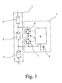
- Fig. 1 shows a solar cell 1, which has a plurality of series-connected strings 2, which in turn consist of several, not shown in detail, also connected in series solar cells.
- the provision of three strings 2 for the solar cell module 1 is purely exemplary.
- the protection via a protection circuit according to a preferred exemplary embodiment of the invention is shown for only one string 2.
- a corresponding safeguard can of course be provided for each string.
- the aim is to provide such a protection circuit, which ensures that in the case of shading the string thus secured a current bypass for this shadowed string is achieved, so that the solar cell module 1 on the one hand remains ready for use, ie one Provides power, and on the other hand damage to the shadowed string 2 is prevented.
- the protection circuit has a controlled electronic switching arrangement 3, which has a drive circuit 4 and a switching device 5.
- the switching device 5 is formed by two switching elements, namely two mutually poled MOSFETs 6, 7, which can be controlled by the drive circuit 4. Moreover, a storage capacitor 8 is provided for the drive circuit 4, so that in case of shading of the protected by the protection circuit string 2 the following sequence is made possible:
- the drive circuit 4 Due to the intrinsic power consumption of the drive circuit 4, the voltage across the storage capacitor 8 and at the gates of the MOSFETs 6, 7 decreases slowly from. Once a voltage is exceeded, in which a complete Aufsteuem the MOSFETs 6, 7 is no longer guaranteed, the drive circuit 4 turns off at least the MOSFET 7 from. Via the MOSFET 7, a voltage builds up, which in turn, as described above, limited. The Leitendphase the MOSFETs 6, 7 takes several tens of milliseconds.
- the drive circuit 4 is further designed such that it is not supplied when lighting the thus secured strings 2, so that the MOSFETs 6, 7 block.
- the MOSFETs 6, 7 In addition to the low reverse currents of the MOSFETs 6, 7 thus occur through the controlled electronic switching device 3 no losses, so that the total losses are in practice even below those of Schottky diodes.
- the protection circuit according to a preferred embodiment of the invention is essential that the controlled electrical switching device in the voltage-limited blocking phase of the remaining, so still lit strings 2 supplies, so that no external supply is required.
- the drive circuit 4 essentially comprises a Schmitt trigger, which is supplied by the drain of the MOSFET 7.
- This Schmitt trigger ensures that the MOSFETs 6, 7 are only turned on when a voltage is applied to the capacitor 8.
- the pulse-pause ratio results from the hysteresis of the Schmitt trigger and the intrinsic current consumption of the switching arrangement 3 in conjunction with the capacitance of the capacitor 8.
- the drive circuit 4 can be particularly simple z.
- a voltage supervisor IC such as the MAX6462 from Maxim Integrated Products.
- a simple additional wiring is required, which has a diode that protects the circuit from the regular poled operating voltage when the string is lit, and a resistor that limits the current through this diode, as long as the MOSFETs are not turned on yet.
- the diode in conjunction with the resistor at the output of the drive circuit 4 limits the voltage across the MOSFETs 6, 7, while the voltage across the capacitor 8 only builds up.
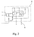
- the drive circuit 4 is a total of essentially a comparator circuit, which may be constructed in detail as well as from Fig. 2 seen.
- This circuit essentially represents a discrete simulation of the aforementioned voltage supervisor IC with the additional circuit also mentioned above.
- a solar cell module usually has a plurality of strings A, B,..., X connected in series, to which at least a switching arrangement 100 is assigned as a protective device.
- strings A, B are shown explicitly, while string X is only indicated by dots and should represent that basically any number of strings can be connected in series.
- Each string A - X consists of several series-connected solar cells 1 - n.
- each string A - X as a protective device to a MOSFET 10 and a DC / DC converter 20 which is connected via an energy storage 30 with a drive circuit 40 in connection.
- a MOSFET 10 is in each case arranged parallel to a string A - X and is connected via its gate to the drive circuit 40. All strings A - X are combined to form a solar cell module and assigned to a converter UM.
- FIG. 4 shows, according to the third preferred embodiment of the invention, two of the strings A - X, namely in each case the two strings A and B and C and D together assigned to a protective device.
- Each solar cell row A and B or C and D has a MOSFET 10 connected in parallel.
- the two MOSFETs 10 are each connected to a common drive circuit 40 via their gate, the supply of the drive circuit 40 being effected by the two DC / DC converters 20, each associated with a string A - X, which are parallel to the series connection of the strings A - X. are connected, wherein one of the DC / DC converter 20, an energy storage 30 is assigned.
- the common protection device for two of the strings A - X is alternately supplied alternately from the voltage applied across a MOSFET 10, because there are two MOSFETs 10 per protection device.
- a sufficient voltage can be obtained from the sum of the forward voltages of the parasitic diodes of the MOSFETs 10 in order to use them for converting and driving the MOSFETs 10. All strings A - X are also combined to form a solar cell module and assigned to a converter UM.
- the DC / DC converter 20 off Fig. 3 can be formed in detail.
- the DC / DC converter 20 which converts the voltage resulting from the shadowing of a string A - X into the internal diode of the MOSFET 10 into a voltage suitable for driving the MOSFET 10, should operate with input voltages below 0.7 V to bypass Ensure function.
- z. B. serve with a germanium transistor 50 constructed Meissner oscillator whose transformer contains a third winding.
- Meissner oscillator reference may be made to the textbook by U. Tietze and Ch. Schenk "Halbleiter-Scenstechnik", 9th edition, p. 461 f.
- a silicon diode 60 arranged antiparallel to the base-emitter path of the transistor 50 serves to protect the transistor 50 against the inverse input voltage present when the string A - X is illuminated.
- the drive circuit 40 consists essentially of a Schmitt trigger which, when a specific threshold voltage is exceeded across the capacitor 30, applies this voltage to the gate of the MOSFET 10 sets and falls below this threshold voltage by a value given by the hysteresis the gate discharges.
- the Schmitt trigger ensures that the MOSFET 10 is only turned on when the capacitor 30, a voltage above the threshold voltage of the MOSFETs 10 is applied.
- the pulse-pause ratio results from the hysteresis of the Schmitt trigger and the self-current consumption of the overall circuit in conjunction with the capacitance of the capacitor 30.
- the Schmitt trigger can be realized particularly easily with a voltage supervisor IC, such as the previously mentioned MAX6462 from Maxim Integrated Products.
- a voltage supervisor IC such as the previously mentioned MAX6462 from Maxim Integrated Products.
- suitable Schmitt trigger circuits are achieved, in particular by the use of logic-level MOSFETs.
- Fig. 6 Now, an example of a drive circuit 40 can be seen in detail, as it practically corresponds to a discrete replica of a voltage supervisor IC.
- protection circuits for solar cells of a solar cell module are thus provided by the invention, which are just as unproblematic as a protective circuit with bypass diodes, but have significantly lower power losses, so that much higher currents can be hedged.
Landscapes
- Photovoltaic Devices (AREA)
- Charge And Discharge Circuits For Batteries Or The Like (AREA)
- Protection Of Static Devices (AREA)
Claims (10)
- Circuit de protection pour le raccordement électrique d'au moins une cellule solaire d'un module à cellules solaires (1), comprenant un dispositif de protection qui présente un arrangement de commutation électronique commandé (3, 100), avec lequel
l'arrangement de commutation électronique commandé (3, 100) présente un circuit de commande (4, 40) et un dispositif de commutation (5, 10) pouvant être commandé par le circuit de commande (4, 40), le dispositif de commutation (5, 10) est branché en parallèle avec au moins une cellule solaire et, dans le cas d'un obscurcissement de la cellule solaire, est au moins temporairement déconnecté par le circuit de commande (4, 40) de manière à obtenir une dérivation de courant pour la cellule solaire obscurcie, caractérisé en ce que le dispositif de protection, dans le cas de la cellule solaire obscurcie, fait office de dérivation de courant parallèle à la cellule solaire obscurcie pour la cellule solaire obscurcie,
le dispositif de commutation (5) présente deux éléments de commutation (6, 7) électriques ou électroniques branchés en série et commandés par le circuit de commande (4) et les éléments de commutation (6, 7) prévus sont deux transistors à polarités opposées. - Circuit de protection selon la revendication 1, caractérisé en ce que les transistors à polarités opposées sont des MOSFET.
- Circuit de protection pour le raccordement électrique d'au moins une cellule solaire d'un module à cellules solaires (1), comprenant un dispositif de protection qui présente un arrangement de commutation électronique commandé (3, 100), avec lequel
l'arrangement de commutation électronique commandé (3, 100) présente un circuit de commande (4, 40) et un dispositif de commutation (5, 10) pouvant être commandé par le circuit de commande (4, 40) et le dispositif de commutation (5, 10) est branché en parallèle avec au moins une cellule solaire et, dans le cas d'un obscurcissement de la cellule solaire, est au moins temporairement déconnecté par le circuit de commande (4, 40) de manière à obtenir une dérivation de courant pour la cellule solaire obscurcie, caractérisé en ce que le dispositif de protection, dans le cas de la cellule solaire obscurcie, fait office de dérivation de courant parallèle à la cellule solaire obscurcie pour la cellule solaire obscurcie, et le dispositif de protection présente au moins un transistor (10) et au moins un convertisseur CC/CC (20) branché en parallèle avec celui-ci, lequel est en liaison avec le circuit de commande (40) par le biais d'un accumulateur d'énergie (30). - Circuit de protection selon la revendication 3, caractérisé en ce que le transistor (10) prévu est un MOSFET.
- Circuit de protection selon la revendication 3 ou 4, caractérisé en ce qu'un dispositif de protection commun est associé à plusieurs chaînes (A - X) de cellules solaires, lequel présente un transistor (10) branché en parallèle avec chaque chaîne (A - X), ledit transistor (10) étant en liaison à chaque fois avec un circuit de commande (40) par le biais de sa gâchette.
- Circuit de protection selon la revendication 5, caractérisé en ce que l'alimentation du circuit de commande (40) de chaque chaîne (A - X) s'effectue par un convertisseur CC/CC (20) correspondant, les convertisseurs CC/CC (20) étant branchés en parallèle avec le circuit série des chaînes (A - X).
- Circuit de protection selon la revendication 6, caractérisé en ce qu'un accumulateur d'énergie (30) est associé à au moins un convertisseur CC/CC (20).
- Circuit de protection selon l'une des revendications 1 à 7, caractérisé en ce que le circuit de commande (40) de l'arrangement de commutation électronique présente un microcontrôleur.
- Circuit de protection selon l'une des revendications 1 à 8, caractérisé en ce que l'alimentation électrique du circuit de commande (4) s'effectue par le biais du courant généré par les cellules solaires non obscurcies du module à cellules solaires (1).
- Circuit de protection selon l'une des revendications 1 à 9, caractérisé en ce qu'un condensateur d'accumulation (8, 30) est prévu pour le circuit de commande (4).
Applications Claiming Priority (4)
| Application Number | Priority Date | Filing Date | Title |
|---|---|---|---|
| DE102005003720 | 2005-01-26 | ||
| DE102005012213A DE102005012213B4 (de) | 2005-01-26 | 2005-03-15 | Anschlußschaltung |
| DE102005018463 | 2005-04-20 | ||
| PCT/EP2006/000599 WO2006079503A2 (fr) | 2005-01-26 | 2006-01-24 | Circuit de protection à dérivation de courant destiné à un module de cellules solaires |
Publications (3)
| Publication Number | Publication Date |
|---|---|
| EP1849189A2 EP1849189A2 (fr) | 2007-10-31 |
| EP1849189B1 EP1849189B1 (fr) | 2012-09-05 |
| EP1849189B9 true EP1849189B9 (fr) | 2012-12-26 |
Family
ID=36694489
Family Applications (1)
| Application Number | Title | Priority Date | Filing Date |
|---|---|---|---|
| EP20060701624 Expired - Lifetime EP1849189B9 (fr) | 2005-01-26 | 2006-01-24 | Circuit de protection a derivation de courant destine a un module de cellules solaires |
Country Status (4)
| Country | Link |
|---|---|
| US (2) | US7864497B2 (fr) |
| EP (1) | EP1849189B9 (fr) |
| ES (1) | ES2393647T3 (fr) |
| WO (1) | WO2006079503A2 (fr) |
Families Citing this family (107)
| Publication number | Priority date | Publication date | Assignee | Title |
|---|---|---|---|---|
| EP1849189B9 (fr) * | 2005-01-26 | 2012-12-26 | Günther Spelsberg GmbH & Co. KG | Circuit de protection a derivation de courant destine a un module de cellules solaires |
| US11881814B2 (en) | 2005-12-05 | 2024-01-23 | Solaredge Technologies Ltd. | Testing of a photovoltaic panel |
| US10693415B2 (en) | 2007-12-05 | 2020-06-23 | Solaredge Technologies Ltd. | Testing of a photovoltaic panel |
| US9112379B2 (en) | 2006-12-06 | 2015-08-18 | Solaredge Technologies Ltd. | Pairing of components in a direct current distributed power generation system |
| US11687112B2 (en) | 2006-12-06 | 2023-06-27 | Solaredge Technologies Ltd. | Distributed power harvesting systems using DC power sources |
| US11855231B2 (en) | 2006-12-06 | 2023-12-26 | Solaredge Technologies Ltd. | Distributed power harvesting systems using DC power sources |
| US9088178B2 (en) | 2006-12-06 | 2015-07-21 | Solaredge Technologies Ltd | Distributed power harvesting systems using DC power sources |
| US11309832B2 (en) | 2006-12-06 | 2022-04-19 | Solaredge Technologies Ltd. | Distributed power harvesting systems using DC power sources |
| US8384243B2 (en) | 2007-12-04 | 2013-02-26 | Solaredge Technologies Ltd. | Distributed power harvesting systems using DC power sources |
| US8963369B2 (en) | 2007-12-04 | 2015-02-24 | Solaredge Technologies Ltd. | Distributed power harvesting systems using DC power sources |
| US11569659B2 (en) | 2006-12-06 | 2023-01-31 | Solaredge Technologies Ltd. | Distributed power harvesting systems using DC power sources |
| US8319471B2 (en) | 2006-12-06 | 2012-11-27 | Solaredge, Ltd. | Battery power delivery module |
| US8319483B2 (en) | 2007-08-06 | 2012-11-27 | Solaredge Technologies Ltd. | Digital average input current control in power converter |
| US8618692B2 (en) | 2007-12-04 | 2013-12-31 | Solaredge Technologies Ltd. | Distributed power system using direct current power sources |
| US8947194B2 (en) | 2009-05-26 | 2015-02-03 | Solaredge Technologies Ltd. | Theft detection and prevention in a power generation system |
| US8013472B2 (en) | 2006-12-06 | 2011-09-06 | Solaredge, Ltd. | Method for distributed power harvesting using DC power sources |
| US8816535B2 (en) | 2007-10-10 | 2014-08-26 | Solaredge Technologies, Ltd. | System and method for protection during inverter shutdown in distributed power installations |
| US11888387B2 (en) | 2006-12-06 | 2024-01-30 | Solaredge Technologies Ltd. | Safety mechanisms, wake up and shutdown methods in distributed power installations |
| US11735910B2 (en) | 2006-12-06 | 2023-08-22 | Solaredge Technologies Ltd. | Distributed power system using direct current power sources |
| US9130401B2 (en) | 2006-12-06 | 2015-09-08 | Solaredge Technologies Ltd. | Distributed power harvesting systems using DC power sources |
| US8473250B2 (en) | 2006-12-06 | 2013-06-25 | Solaredge, Ltd. | Monitoring of distributed power harvesting systems using DC power sources |
| US11296650B2 (en) | 2006-12-06 | 2022-04-05 | Solaredge Technologies Ltd. | System and method for protection during inverter shutdown in distributed power installations |
| US12316274B2 (en) | 2006-12-06 | 2025-05-27 | Solaredge Technologies Ltd. | Pairing of components in a direct current distributed power generation system |
| US20090014050A1 (en) * | 2007-07-13 | 2009-01-15 | Peter Haaf | Solar module system and method using transistors for bypass |
| DE102008004675B3 (de) * | 2007-10-12 | 2009-03-05 | Fraunhofer-Gesellschaft zur Förderung der angewandten Forschung e.V. | Steuerbare Umschaltvorrichtung für ein Solarmodul |
| US9142964B2 (en) * | 2007-11-14 | 2015-09-22 | Renergyx Pty Limited | Electrical energy and distribution system |
| US8289742B2 (en) | 2007-12-05 | 2012-10-16 | Solaredge Ltd. | Parallel connected inverters |
| US9291696B2 (en) | 2007-12-05 | 2016-03-22 | Solaredge Technologies Ltd. | Photovoltaic system power tracking method |
| US11264947B2 (en) | 2007-12-05 | 2022-03-01 | Solaredge Technologies Ltd. | Testing of a photovoltaic panel |
| CN105244905B (zh) | 2007-12-05 | 2019-05-21 | 太阳能安吉有限公司 | 分布式电力装置中的安全机构、醒来和关闭方法 |
| WO2009072076A2 (fr) | 2007-12-05 | 2009-06-11 | Solaredge Technologies Ltd. | Détection de courant sur un transistor mosfet |
| US20090184746A1 (en) * | 2008-01-22 | 2009-07-23 | Microsemi Corporation | Low Voltage Drop Unidirectional Electronic Valve |
| EP2269290B1 (fr) | 2008-03-24 | 2018-12-19 | Solaredge Technologies Ltd. | Convertisseur à découpage avec un verrouillage actife pour commutation à tension nulle |
| DE102008021654B3 (de) * | 2008-04-30 | 2009-12-10 | Insta Elektro Gmbh | Verfahren zum Betrieb einer Fotovoltaikanlage sowie Fotovoltaikanlage |
| EP2294669B8 (fr) | 2008-05-05 | 2016-12-07 | Solaredge Technologies Ltd. | Circuit combinateur de puissance de courant continu |
| SG160241A1 (en) * | 2008-09-15 | 2010-04-29 | Alternative Energy Technology | Photovoltaic cell circuit |
| US8791598B2 (en) * | 2008-12-21 | 2014-07-29 | NavSemi Energy Private Ltd. | System and method for selectively controlling a solar panel in segments |
| JP2012527767A (ja) | 2009-05-22 | 2012-11-08 | ソラレッジ テクノロジーズ リミテッド | 電気絶縁された熱放散接続箱 |
| JP5398912B2 (ja) * | 2009-07-09 | 2014-01-29 | マイクロセミ コーポレィション | 低電圧降下閉ループ単方向電子バルブ |
| US8791602B2 (en) * | 2009-08-17 | 2014-07-29 | NavSemi Energy Private Ltd. | System and method for controlling a solar panel output |
| DE102009042084A1 (de) * | 2009-09-18 | 2011-06-22 | Gehrlicher Solar AG, 85609 | Wartungsarmes elektronisches Bauelement zur Verhinderung von Rückströmen bei gleichzeitigem Schutz vor Überströmen in Photovoltaikanlagen |
| US8263920B2 (en) * | 2009-09-30 | 2012-09-11 | The Boeing Company | Diodeless terrestrial photovoltaic solar power array |
| US9324885B2 (en) * | 2009-10-02 | 2016-04-26 | Tigo Energy, Inc. | Systems and methods to provide enhanced diode bypass paths |
| US12418177B2 (en) | 2009-10-24 | 2025-09-16 | Solaredge Technologies Ltd. | Distributed power system using direct current power sources |
| DE102009044695A1 (de) * | 2009-11-27 | 2011-06-01 | Müller, Ingo, Dr. | Solarmodul, Modulschalter, Solarkabel, Sammelschiene, Mehrfachkontakt-Steckverbinder |
| US8710699B2 (en) | 2009-12-01 | 2014-04-29 | Solaredge Technologies Ltd. | Dual use photovoltaic system |
| US8766696B2 (en) | 2010-01-27 | 2014-07-01 | Solaredge Technologies Ltd. | Fast voltage level shifter circuit |
| US9425783B2 (en) | 2010-03-15 | 2016-08-23 | Tigo Energy, Inc. | Systems and methods to provide enhanced diode bypass paths |
| KR101078799B1 (ko) | 2010-03-23 | 2011-11-02 | 엘지전자 주식회사 | 태양광 발전 시스템 |
| US9136731B2 (en) | 2010-04-27 | 2015-09-15 | NavSemi Energy Private Ltd. | Method and apparatus for controlling a solar panel output in charging a battery |
| IT1400921B1 (it) | 2010-05-14 | 2013-07-02 | St Microelectronics Srl | Diodo di by-pass o interruttore realizzato con un mosfet a bassa resistenza di conduzione e relativo circuito di controllo autoalimentato |
| DE102010023549B4 (de) * | 2010-06-03 | 2016-03-24 | Dmos Gmbh | Photovoltaikgenerator mit Schaltungsanlage und Verfahren zum Schutz von Photovoltaikmodulen |
| EP2395550B1 (fr) * | 2010-06-09 | 2013-10-09 | SMA Solar Technology AG | Procédé de reconnaissance et d'évaluation d'obscurcissements |
| DE102010036816A1 (de) * | 2010-08-03 | 2012-02-09 | Newtos Ag | Verfahren und Vorrichtung zur Überwachung und Steuerung einer Photovoltaik-Anlage |
| US20120049855A1 (en) * | 2010-08-24 | 2012-03-01 | Crites David E | Dark IV monitoring system for photovoltaic installations |
| US10615743B2 (en) * | 2010-08-24 | 2020-04-07 | David Crites | Active and passive monitoring system for installed photovoltaic strings, substrings, and modules |
| US10230310B2 (en) * | 2016-04-05 | 2019-03-12 | Solaredge Technologies Ltd | Safety switch for photovoltaic systems |
| US10673229B2 (en) | 2010-11-09 | 2020-06-02 | Solaredge Technologies Ltd. | Arc detection and prevention in a power generation system |
| US10673222B2 (en) | 2010-11-09 | 2020-06-02 | Solaredge Technologies Ltd. | Arc detection and prevention in a power generation system |
| GB2485527B (en) | 2010-11-09 | 2012-12-19 | Solaredge Technologies Ltd | Arc detection and prevention in a power generation system |
| GB2486408A (en) | 2010-12-09 | 2012-06-20 | Solaredge Technologies Ltd | Disconnection of a string carrying direct current |
| GB2483317B (en) | 2011-01-12 | 2012-08-22 | Solaredge Technologies Ltd | Serially connected inverters |
| DE102012010083B4 (de) * | 2011-05-23 | 2023-04-27 | Microsemi Corp. | Photovoltaische Sicherheitsabschaltungsvorrichtung |
| US8570005B2 (en) | 2011-09-12 | 2013-10-29 | Solaredge Technologies Ltd. | Direct current link circuit |
| GB2498365A (en) | 2012-01-11 | 2013-07-17 | Solaredge Technologies Ltd | Photovoltaic module |
| GB2498790A (en) | 2012-01-30 | 2013-07-31 | Solaredge Technologies Ltd | Maximising power in a photovoltaic distributed power system |
| GB2498791A (en) | 2012-01-30 | 2013-07-31 | Solaredge Technologies Ltd | Photovoltaic panel circuitry |
| US9853565B2 (en) | 2012-01-30 | 2017-12-26 | Solaredge Technologies Ltd. | Maximized power in a photovoltaic distributed power system |
| GB2499991A (en) | 2012-03-05 | 2013-09-11 | Solaredge Technologies Ltd | DC link circuit for photovoltaic array |
| CN108306333B (zh) | 2012-05-25 | 2022-03-08 | 太阳能安吉科技有限公司 | 用于互联的直流电源的电路 |
| US10115841B2 (en) | 2012-06-04 | 2018-10-30 | Solaredge Technologies Ltd. | Integrated photovoltaic panel circuitry |
| US9105765B2 (en) * | 2012-12-18 | 2015-08-11 | Enphase Energy, Inc. | Smart junction box for a photovoltaic system |
| US9941813B2 (en) | 2013-03-14 | 2018-04-10 | Solaredge Technologies Ltd. | High frequency multi-level inverter |
| US9548619B2 (en) | 2013-03-14 | 2017-01-17 | Solaredge Technologies Ltd. | Method and apparatus for storing and depleting energy |
| EP2779251B1 (fr) | 2013-03-15 | 2019-02-27 | Solaredge Technologies Ltd. | Mécanisme de dérivation |
| DE102013106808A1 (de) * | 2013-06-28 | 2014-12-31 | Sma Solar Technology Ag | Schaltungsanordnung zur Inline-Spannungsversorgung |
| CN103888057A (zh) * | 2014-03-07 | 2014-06-25 | 苏州边枫电子科技有限公司 | 基于远红外热传感器的过温状态指示型光伏接线盒 |
| CN103888059A (zh) * | 2014-03-07 | 2014-06-25 | 苏州边枫电子科技有限公司 | 基于测电压的过温状态指示型光伏接线盒 |
| CN103888058A (zh) * | 2014-03-07 | 2014-06-25 | 苏州边枫电子科技有限公司 | 基于测电流的过温状态指示型光伏接线盒 |
| CN103888060A (zh) * | 2014-03-07 | 2014-06-25 | 苏州边枫电子科技有限公司 | 基于半导体测温的过温状态指示型光伏接线盒 |
| US9318974B2 (en) | 2014-03-26 | 2016-04-19 | Solaredge Technologies Ltd. | Multi-level inverter with flying capacitor topology |
| CN103888072A (zh) * | 2014-04-03 | 2014-06-25 | 苏州边枫电子科技有限公司 | 基于热敏电阻测温和单线通讯协议的远程监控型光伏接线盒 |
| CN103888067A (zh) * | 2014-04-03 | 2014-06-25 | 苏州边枫电子科技有限公司 | 基于霍尔传感器和fm传输的远程监控型光伏接线盒 |
| CN103888061A (zh) * | 2014-04-03 | 2014-06-25 | 苏州边枫电子科技有限公司 | 基于半导体测温和fm传输的远程监控型光伏接线盒 |
| CN103888062A (zh) * | 2014-04-03 | 2014-06-25 | 苏州边枫电子科技有限公司 | 基于测电流和电力导线载波的远程监控型光伏接线盒 |
| CN107210698A (zh) | 2014-06-19 | 2017-09-26 | 李平 | 电机、发电机和直流切换器系统、装置和方法 |
| WO2015200366A1 (fr) * | 2014-06-24 | 2015-12-30 | Ping Li | Système et procédé d'empilement actif de batteries |
| US20160079761A1 (en) * | 2014-09-15 | 2016-03-17 | The Board Of Trustees Of The University Of Illinois | System and method for power point tracking for photovoltaic cells |
| DE102015012413A1 (de) * | 2015-04-14 | 2016-10-20 | Smartexergy Wms Gmbh | Überbrückungsvorrichtung für mindestens ein Photovoltaikmodul |
| US11081608B2 (en) | 2016-03-03 | 2021-08-03 | Solaredge Technologies Ltd. | Apparatus and method for determining an order of power devices in power generation systems |
| CN107153212B (zh) | 2016-03-03 | 2023-07-28 | 太阳能安吉科技有限公司 | 用于映射发电设施的方法 |
| US10599113B2 (en) | 2016-03-03 | 2020-03-24 | Solaredge Technologies Ltd. | Apparatus and method for determining an order of power devices in power generation systems |
| DE102016105930A1 (de) * | 2016-03-31 | 2017-10-05 | Sma Solar Technology Ag | Solarmodul, Betriebsverfahren Für ein Solarmodul und Photovoltaikanlage |
| US12057807B2 (en) | 2016-04-05 | 2024-08-06 | Solaredge Technologies Ltd. | Chain of power devices |
| US11018623B2 (en) | 2016-04-05 | 2021-05-25 | Solaredge Technologies Ltd. | Safety switch for photovoltaic systems |
| US11177663B2 (en) | 2016-04-05 | 2021-11-16 | Solaredge Technologies Ltd. | Chain of power devices |
| EP3291309B1 (fr) * | 2016-08-29 | 2022-08-24 | Solaredge Technologies Ltd. | Commutateur de sécurité pour des systèmes photovoltaïques |
| US20180013377A1 (en) * | 2016-07-11 | 2018-01-11 | International Business Machines Corporation | Mitigating the Effects on Shading in Photovoltaic Cells Using Flow Batteries |
| DE102016115295A1 (de) | 2016-08-17 | 2018-02-22 | Sma Solar Technology Ag | Trennvorrichtung für einen photovoltaischen String |
| US12395068B2 (en) | 2017-03-29 | 2025-08-19 | Solaredge Technologies Ltd. | Bypass circuit and method to bypass power modules in power system |
| CN108695843B (zh) * | 2017-03-29 | 2023-09-22 | 太阳能安吉科技有限公司 | 旁路电路和在电力系统中旁通电力模块的方法 |
| EP3611815A1 (fr) * | 2018-08-17 | 2020-02-19 | Solaredge Technologies Ltd. | Circuit de dérivation et procédé de déviation de modules de puissance dans un système d'alimentation |
| EP3709491A1 (fr) * | 2019-03-12 | 2020-09-16 | ABB Schweiz AG | Onduleur multicanal destiné à un appareil photovoltaïque |
| WO2020219995A1 (fr) * | 2019-04-25 | 2020-10-29 | Aerovironment | Système et procédé de diagnostic de réseau de cellules solaires dans un aéronef à grande autonomie à haute altitude |
| US11855451B2 (en) * | 2020-09-25 | 2023-12-26 | Analog Devices International Unlimited Company | Bootstrapped line-protector CMOS switch |
| CN113644876B (zh) * | 2021-08-12 | 2023-11-24 | 阳光新能源开发股份有限公司 | 一种光伏发电系统和光伏组件的保护电路 |
| DE102024116342B4 (de) * | 2024-06-11 | 2026-04-02 | Sma Solar Technology Ag | PV-Anlage mit Sammeleinheiten, Verfahren zum Betrieb einer PV-Anlage mit Sammeleinheiten und Sammeleinheit für PV-Stränge |
Family Cites Families (10)
| Publication number | Priority date | Publication date | Assignee | Title |
|---|---|---|---|---|
| US3600599A (en) * | 1968-10-03 | 1971-08-17 | Trw Inc | Shunt regulation electric power system |
| US5367310A (en) * | 1991-10-11 | 1994-11-22 | Southwest Research Institute | Fiber optic antenna radiation efficiency tuner |
| JP2666754B2 (ja) | 1994-12-19 | 1997-10-22 | 日本電気株式会社 | 太陽電池電源装置における電力供給方法 |
| JP2000174308A (ja) * | 1998-12-01 | 2000-06-23 | Toshiba Corp | 太陽電池発電モジュール |
| DE19904561C1 (de) * | 1999-02-04 | 2000-08-24 | Rossendorf Forschzent | Verfahren und Schaltungsanordnung zur Maximum-Power-Point-Steuerung von Solargeneratoren |
| DE19916742C1 (de) * | 1999-04-13 | 2000-08-24 | Angew Solarenergie Ase Gmbh | Schaltungsanordnung zur Stromerzeugung mit Solarzellen |
| US6246219B1 (en) * | 2000-03-24 | 2001-06-12 | The Boeing Company | String switching apparatus and associated method for controllably connecting the output of a solar array string to a respective power bus |
| DE10222621A1 (de) * | 2002-05-17 | 2003-11-27 | Josef Steger | Verfahren und Schaltungsanordnung zur Steuer- und Regelung von Photovoltaikanlagen |
| US7612283B2 (en) * | 2002-07-09 | 2009-11-03 | Canon Kabushiki Kaisha | Solar power generation apparatus and its manufacturing method |
| EP1849189B9 (fr) * | 2005-01-26 | 2012-12-26 | Günther Spelsberg GmbH & Co. KG | Circuit de protection a derivation de courant destine a un module de cellules solaires |
-
2006
- 2006-01-24 EP EP20060701624 patent/EP1849189B9/fr not_active Expired - Lifetime
- 2006-01-24 WO PCT/EP2006/000599 patent/WO2006079503A2/fr not_active Ceased
- 2006-01-24 ES ES06701624T patent/ES2393647T3/es not_active Expired - Lifetime
- 2006-01-24 US US11/814,045 patent/US7864497B2/en active Active
-
2010
- 2010-11-29 US US12/955,322 patent/US8139335B2/en not_active Expired - Fee Related
Also Published As
| Publication number | Publication date |
|---|---|
| WO2006079503A2 (fr) | 2006-08-03 |
| WO2006079503A3 (fr) | 2006-11-30 |
| US8139335B2 (en) | 2012-03-20 |
| US7864497B2 (en) | 2011-01-04 |
| EP1849189B1 (fr) | 2012-09-05 |
| US20110068633A1 (en) | 2011-03-24 |
| EP1849189A2 (fr) | 2007-10-31 |
| US20090195081A1 (en) | 2009-08-06 |
| ES2393647T3 (es) | 2012-12-26 |
Similar Documents
| Publication | Publication Date | Title |
|---|---|---|
| EP1849189B9 (fr) | Circuit de protection a derivation de courant destine a un module de cellules solaires | |
| DE102005012213B4 (de) | Anschlußschaltung | |
| DE102005036153B4 (de) | Schutzschalteinrichtung für ein Solarmodul | |
| EP1914857B1 (fr) | Dispositif de circuit électrique et procédé, en particulier pour des générateurs photovoltaic | |
| DE10120595B4 (de) | Solarenergiesystem | |
| EP2342807B1 (fr) | Convertisseur avec au moins un commutateur normalement ouvert | |
| EP2591530B1 (fr) | Circuit permettant de protéger un consommateur électrique contre des surtensions | |
| EP3853957B1 (fr) | Commutateur électronique à protection contre les surtensions | |
| EP2179451A1 (fr) | Dispositif de commutation régulable pour module solaire | |
| DE102006023563A1 (de) | Photovoltaik-Anlage | |
| DE102005012662B4 (de) | Anordnung mit Spannungskonverter zur Spannungsversorgung einer elektrischen Last und Verfahren zur Spannungsversorgung einer elektrischen Last | |
| DE102016102417A1 (de) | Schutzschaltung für ein Photovoltaik (PV)-Modul, Verfahren zum Betrieb der Schutzschaltung und Photovoltaik (PV)-Anlage mit einer derartigen Schutzschaltung | |
| DE112016000220T5 (de) | Leistungswandlungsausrüstung | |
| CH660266A5 (de) | Thyristoreinrichtung mit durch licht steuerbaren thyristoren. | |
| DE2320128B2 (de) | Zerhacker | |
| DE102010060463B4 (de) | Schaltungsanordnung zur Potentialeinstellung eines Photovoltaikgenerators und Photovoltaikanlage | |
| DE19635606A1 (de) | Vorrichtung zur Erzeugung einer höheren Wechselspannung aus mehreren niedrigeren Gleichspannungen und dafür geeigneter Bausatz | |
| DE3429488C2 (fr) | ||
| DE2644715A1 (de) | Einrichtung zur befreiung elektrischer oder elektronischer einwegschalter von hoher verlustleistungsbeanspruchung waehrend des einschaltens und ueberhoehter sperrspannungsbeanspruchung beim ausschalten | |
| DE102011055371B4 (de) | Leistungsbegrenzte Generatorerdung - Schaltungsanordnung und Photovoltaikwechselrichter mit Schaltungsanordnung | |
| DE102008020030B4 (de) | Schaltungsanordnung mit einem Gleichrichter und einer Schaltung zum Schutz zumindest eines an die Schaltungsanordnung anschließbaren Gleichstromnetzes mit Gleichstromverbrauchern gegen Überspannung | |
| EP0829123B1 (fr) | Circuit de roue libre a duree de temporisation d'arret reglable | |
| DE2724741A1 (de) | Schutzbeschaltung fuer jeweils ein stromrichterventil | |
| EP2774255B1 (fr) | Convertisseur de tension comportant un premier circuit parallèle | |
| DE202016103031U1 (de) | Ansteuerbare Bypass-Diode |
Legal Events
| Date | Code | Title | Description |
|---|---|---|---|
| PUAI | Public reference made under article 153(3) epc to a published international application that has entered the european phase |
Free format text: ORIGINAL CODE: 0009012 |
|
| 17P | Request for examination filed |
Effective date: 20070316 |
|
| AK | Designated contracting states |
Kind code of ref document: A2 Designated state(s): AT BE BG CH CY CZ DE DK EE ES FI FR GB GR HU IE IS IT LI LT LU LV MC NL PL PT RO SE SI SK TR |
|
| DAX | Request for extension of the european patent (deleted) | ||
| 17Q | First examination report despatched |
Effective date: 20081208 |
|
| RAP1 | Party data changed (applicant data changed or rights of an application transferred) |
Owner name: INSTA ELEKTRO GMBH Owner name: GUENTHER SPELSBERG GMBH & CO. KG |
|
| RAP1 | Party data changed (applicant data changed or rights of an application transferred) |
Owner name: INSTA ELEKTRO GMBH Owner name: GUENTHER SPELSBERG GMBH & CO. KG |
|
| RTI1 | Title (correction) |
Free format text: PROTECTIVE CIRCUIT WITH CURRENT BYPASS FOR SOLAR CELL MODULE AND ITS USE |
|
| REG | Reference to a national code |
Ref country code: DE Ref legal event code: R079 Ref document number: 502006011940 Country of ref document: DE Free format text: PREVIOUS MAIN CLASS: H01L0027142000 Ipc: H01L0031042000 |
|
| GRAP | Despatch of communication of intention to grant a patent |
Free format text: ORIGINAL CODE: EPIDOSNIGR1 |
|
| RIC1 | Information provided on ipc code assigned before grant |
Ipc: H01L 27/142 20060101ALI20120309BHEP Ipc: H01L 31/042 20060101AFI20120309BHEP Ipc: H01L 31/02 20060101ALI20120309BHEP |
|
| RTI1 | Title (correction) |
Free format text: PROTECTIVE CIRCUIT WITH CURRENT BYPASS FOR SOLAR CELL MODULE |
|
| GRAS | Grant fee paid |
Free format text: ORIGINAL CODE: EPIDOSNIGR3 |
|
| GRAA | (expected) grant |
Free format text: ORIGINAL CODE: 0009210 |
|
| AK | Designated contracting states |
Kind code of ref document: B1 Designated state(s): AT BE BG CH CY CZ DE DK EE ES FI FR GB GR HU IE IS IT LI LT LU LV MC NL PL PT RO SE SI SK TR |
|
| REG | Reference to a national code |
Ref country code: DE Ref legal event code: R081 Ref document number: 502006011940 Country of ref document: DE Owner name: FRAUNHOFER-GESELLSCHAFT ZUR FOERDERUNG DER ANG, DE Free format text: FORMER OWNERS: GUENTHER SPELSBERG GMBH & CO. KG, 58579 SCHALKSMUEHLE, DE; INSTA ELEKTRO GMBH, 58509 LUEDENSCHEID, DE Ref country code: GB Ref legal event code: FG4D Free format text: NOT ENGLISH |
|
| REG | Reference to a national code |
Ref country code: CH Ref legal event code: EP |
|
| REG | Reference to a national code |
Ref country code: AT Ref legal event code: REF Ref document number: 574463 Country of ref document: AT Kind code of ref document: T Effective date: 20120915 |
|
| REG | Reference to a national code |
Ref country code: IE Ref legal event code: FG4D Free format text: LANGUAGE OF EP DOCUMENT: GERMAN |
|
| REG | Reference to a national code |
Ref country code: DE Ref legal event code: R096 Ref document number: 502006011940 Country of ref document: DE Effective date: 20121031 |
|
| REG | Reference to a national code |
Ref country code: ES Ref legal event code: FG2A Ref document number: 2393647 Country of ref document: ES Kind code of ref document: T3 Effective date: 20121226 |
|
| REG | Reference to a national code |
Ref country code: NL Ref legal event code: T3 |
|
| PG25 | Lapsed in a contracting state [announced via postgrant information from national office to epo] |
Ref country code: LT Free format text: LAPSE BECAUSE OF FAILURE TO SUBMIT A TRANSLATION OF THE DESCRIPTION OR TO PAY THE FEE WITHIN THE PRESCRIBED TIME-LIMIT Effective date: 20120905 Ref country code: CY Free format text: LAPSE BECAUSE OF FAILURE TO SUBMIT A TRANSLATION OF THE DESCRIPTION OR TO PAY THE FEE WITHIN THE PRESCRIBED TIME-LIMIT Effective date: 20120905 Ref country code: FI Free format text: LAPSE BECAUSE OF FAILURE TO SUBMIT A TRANSLATION OF THE DESCRIPTION OR TO PAY THE FEE WITHIN THE PRESCRIBED TIME-LIMIT Effective date: 20120905 |
|
| REG | Reference to a national code |
Ref country code: LT Ref legal event code: MG4D Effective date: 20120905 |
|
| PG25 | Lapsed in a contracting state [announced via postgrant information from national office to epo] |
Ref country code: SI Free format text: LAPSE BECAUSE OF FAILURE TO SUBMIT A TRANSLATION OF THE DESCRIPTION OR TO PAY THE FEE WITHIN THE PRESCRIBED TIME-LIMIT Effective date: 20120905 Ref country code: GR Free format text: LAPSE BECAUSE OF FAILURE TO SUBMIT A TRANSLATION OF THE DESCRIPTION OR TO PAY THE FEE WITHIN THE PRESCRIBED TIME-LIMIT Effective date: 20121206 Ref country code: LV Free format text: LAPSE BECAUSE OF FAILURE TO SUBMIT A TRANSLATION OF THE DESCRIPTION OR TO PAY THE FEE WITHIN THE PRESCRIBED TIME-LIMIT Effective date: 20120905 Ref country code: SE Free format text: LAPSE BECAUSE OF FAILURE TO SUBMIT A TRANSLATION OF THE DESCRIPTION OR TO PAY THE FEE WITHIN THE PRESCRIBED TIME-LIMIT Effective date: 20120905 |
|
| PG25 | Lapsed in a contracting state [announced via postgrant information from national office to epo] |
Ref country code: RO Free format text: LAPSE BECAUSE OF FAILURE TO SUBMIT A TRANSLATION OF THE DESCRIPTION OR TO PAY THE FEE WITHIN THE PRESCRIBED TIME-LIMIT Effective date: 20120905 Ref country code: IS Free format text: LAPSE BECAUSE OF FAILURE TO SUBMIT A TRANSLATION OF THE DESCRIPTION OR TO PAY THE FEE WITHIN THE PRESCRIBED TIME-LIMIT Effective date: 20130105 Ref country code: EE Free format text: LAPSE BECAUSE OF FAILURE TO SUBMIT A TRANSLATION OF THE DESCRIPTION OR TO PAY THE FEE WITHIN THE PRESCRIBED TIME-LIMIT Effective date: 20120905 |
|
| PG25 | Lapsed in a contracting state [announced via postgrant information from national office to epo] |
Ref country code: PT Free format text: LAPSE BECAUSE OF FAILURE TO SUBMIT A TRANSLATION OF THE DESCRIPTION OR TO PAY THE FEE WITHIN THE PRESCRIBED TIME-LIMIT Effective date: 20130107 Ref country code: PL Free format text: LAPSE BECAUSE OF FAILURE TO SUBMIT A TRANSLATION OF THE DESCRIPTION OR TO PAY THE FEE WITHIN THE PRESCRIBED TIME-LIMIT Effective date: 20120905 Ref country code: SK Free format text: LAPSE BECAUSE OF FAILURE TO SUBMIT A TRANSLATION OF THE DESCRIPTION OR TO PAY THE FEE WITHIN THE PRESCRIBED TIME-LIMIT Effective date: 20120905 |
|
| PLBE | No opposition filed within time limit |
Free format text: ORIGINAL CODE: 0009261 |
|
| STAA | Information on the status of an ep patent application or granted ep patent |
Free format text: STATUS: NO OPPOSITION FILED WITHIN TIME LIMIT |
|
| BERE | Be: lapsed |
Owner name: GUNTHER SPELSBERG G.M.B.H. & CO. KG Effective date: 20130131 Owner name: INSTA ELEKTRO G.M.B.H. Effective date: 20130131 |
|
| PG25 | Lapsed in a contracting state [announced via postgrant information from national office to epo] |
Ref country code: DK Free format text: LAPSE BECAUSE OF FAILURE TO SUBMIT A TRANSLATION OF THE DESCRIPTION OR TO PAY THE FEE WITHIN THE PRESCRIBED TIME-LIMIT Effective date: 20120905 Ref country code: BG Free format text: LAPSE BECAUSE OF FAILURE TO SUBMIT A TRANSLATION OF THE DESCRIPTION OR TO PAY THE FEE WITHIN THE PRESCRIBED TIME-LIMIT Effective date: 20121205 |
|
| 26N | No opposition filed |
Effective date: 20130606 |
|
| PG25 | Lapsed in a contracting state [announced via postgrant information from national office to epo] |
Ref country code: IT Free format text: LAPSE BECAUSE OF FAILURE TO SUBMIT A TRANSLATION OF THE DESCRIPTION OR TO PAY THE FEE WITHIN THE PRESCRIBED TIME-LIMIT Effective date: 20120905 Ref country code: MC Free format text: LAPSE BECAUSE OF NON-PAYMENT OF DUE FEES Effective date: 20130131 |
|
| REG | Reference to a national code |
Ref country code: DE Ref legal event code: R097 Ref document number: 502006011940 Country of ref document: DE Effective date: 20130606 |
|
| REG | Reference to a national code |
Ref country code: IE Ref legal event code: MM4A |
|
| PG25 | Lapsed in a contracting state [announced via postgrant information from national office to epo] |
Ref country code: BE Free format text: LAPSE BECAUSE OF NON-PAYMENT OF DUE FEES Effective date: 20130131 |
|
| PG25 | Lapsed in a contracting state [announced via postgrant information from national office to epo] |
Ref country code: IE Free format text: LAPSE BECAUSE OF NON-PAYMENT OF DUE FEES Effective date: 20130124 |
|
| PG25 | Lapsed in a contracting state [announced via postgrant information from national office to epo] |
Ref country code: TR Free format text: LAPSE BECAUSE OF FAILURE TO SUBMIT A TRANSLATION OF THE DESCRIPTION OR TO PAY THE FEE WITHIN THE PRESCRIBED TIME-LIMIT Effective date: 20120905 |
|
| PG25 | Lapsed in a contracting state [announced via postgrant information from national office to epo] |
Ref country code: LU Free format text: LAPSE BECAUSE OF NON-PAYMENT OF DUE FEES Effective date: 20130124 Ref country code: HU Free format text: LAPSE BECAUSE OF FAILURE TO SUBMIT A TRANSLATION OF THE DESCRIPTION OR TO PAY THE FEE WITHIN THE PRESCRIBED TIME-LIMIT; INVALID AB INITIO Effective date: 20060124 |
|
| REG | Reference to a national code |
Ref country code: FR Ref legal event code: PLFP Year of fee payment: 11 |
|
| REG | Reference to a national code |
Ref country code: DE Ref legal event code: R082 Ref document number: 502006011940 Country of ref document: DE Representative=s name: MICHALSKI HUETTERMANN & PARTNER PATENTANWAELTE, DE Ref country code: DE Ref legal event code: R081 Ref document number: 502006011940 Country of ref document: DE Owner name: FRAUNHOFER-GESELLSCHAFT ZUR FOERDERUNG DER ANG, DE Free format text: FORMER OWNERS: GUENTHER SPELSBERG GMBH & CO. KG, 58579 SCHALKSMUEHLE, DE; INSTA ELEKTRO GMBH, 58509 LUEDENSCHEID, DE |
|
| REG | Reference to a national code |
Ref country code: CH Ref legal event code: PUE Owner name: FRAUNHOFER-GESELLSCHAFT ZUR FOERDERUNG DER ANG, DE Free format text: FORMER OWNER: GUENTHER SPELSBERG GMBH AND CO. KG, DE |
|
| REG | Reference to a national code |
Ref country code: ES Ref legal event code: PC2A Owner name: FRAUNHOFER GESELLSCHATFT ZUR FOERDERUNG DER ANGEWA Effective date: 20160303 Ref country code: GB Ref legal event code: 732E Free format text: REGISTERED BETWEEN 20160211 AND 20160217 |
|
| REG | Reference to a national code |
Ref country code: FR Ref legal event code: TP Owner name: GUNTHER SPELSBERG GMBH & CO. KG, DE Effective date: 20160308 |
|
| REG | Reference to a national code |
Ref country code: AT Ref legal event code: PC Ref document number: 574463 Country of ref document: AT Kind code of ref document: T Owner name: FRAUENHOFER GESELLSCHAFT ZUR FOERDERUNG DER AN, DE Effective date: 20160426 |
|
| REG | Reference to a national code |
Ref country code: NL Ref legal event code: PD Owner name: FRAUNHOFER GESELLSCHAFT ZUR FOERDERUNG DER ANGEWA Free format text: DETAILS ASSIGNMENT: VERANDERING VAN EIGENAAR(S), OVERDRACHT; FORMER OWNER NAME: INSTA ELEKTRO GMBH Effective date: 20160127 |
|
| REG | Reference to a national code |
Ref country code: FR Ref legal event code: PLFP Year of fee payment: 12 |
|
| REG | Reference to a national code |
Ref country code: FR Ref legal event code: PLFP Year of fee payment: 13 |
|
| REG | Reference to a national code |
Ref country code: DE Ref legal event code: R079 Ref document number: 502006011940 Country of ref document: DE Free format text: PREVIOUS MAIN CLASS: H01L0031042000 Ipc: H10F0019000000 |
|
| PGFP | Annual fee paid to national office [announced via postgrant information from national office to epo] |
Ref country code: NL Payment date: 20250122 Year of fee payment: 20 |
|
| PGFP | Annual fee paid to national office [announced via postgrant information from national office to epo] |
Ref country code: DE Payment date: 20250120 Year of fee payment: 20 |
|
| PGFP | Annual fee paid to national office [announced via postgrant information from national office to epo] |
Ref country code: ES Payment date: 20250214 Year of fee payment: 20 |
|
| PGFP | Annual fee paid to national office [announced via postgrant information from national office to epo] |
Ref country code: CH Payment date: 20250201 Year of fee payment: 20 Ref country code: AT Payment date: 20250120 Year of fee payment: 20 |
|
| PGFP | Annual fee paid to national office [announced via postgrant information from national office to epo] |
Ref country code: FR Payment date: 20250122 Year of fee payment: 20 Ref country code: CZ Payment date: 20250110 Year of fee payment: 20 |
|
| PGFP | Annual fee paid to national office [announced via postgrant information from national office to epo] |
Ref country code: GB Payment date: 20250123 Year of fee payment: 20 |
|
| REG | Reference to a national code |
Ref country code: CH Ref legal event code: H14 Free format text: ST27 STATUS EVENT CODE: U-0-0-H10-H14 (AS PROVIDED BY THE NATIONAL OFFICE) Effective date: 20260124 Ref country code: DE Ref legal event code: R071 Ref document number: 502006011940 Country of ref document: DE |
|
| REG | Reference to a national code |
Ref country code: NL Ref legal event code: MK Effective date: 20260123 |
|
| REG | Reference to a national code |
Ref country code: ES Ref legal event code: FD2A Effective date: 20260130 |
|
| REG | Reference to a national code |
Ref country code: GB Ref legal event code: PE20 Expiry date: 20260123 |
|
| REG | Reference to a national code |
Ref country code: AT Ref legal event code: MK07 Ref document number: 574463 Country of ref document: AT Kind code of ref document: T Effective date: 20260124 |
|
| PG25 | Lapsed in a contracting state [announced via postgrant information from national office to epo] |
Ref country code: ES Free format text: LAPSE BECAUSE OF EXPIRATION OF PROTECTION Effective date: 20260125 |