EP1849344A2 - Dispositif de commande de matières granuleuses - Google Patents
Dispositif de commande de matières granuleuses Download PDFInfo
- Publication number
- EP1849344A2 EP1849344A2 EP07008074A EP07008074A EP1849344A2 EP 1849344 A2 EP1849344 A2 EP 1849344A2 EP 07008074 A EP07008074 A EP 07008074A EP 07008074 A EP07008074 A EP 07008074A EP 1849344 A2 EP1849344 A2 EP 1849344A2
- Authority
- EP
- European Patent Office
- Prior art keywords
- frame
- reservoir
- storage container
- funnel
- wall
- Prior art date
- Legal status (The legal status is an assumption and is not a legal conclusion. Google has not performed a legal analysis and makes no representation as to the accuracy of the status listed.)
- Withdrawn
Links
Images





Classifications
-
- A—HUMAN NECESSITIES
- A01—AGRICULTURE; FORESTRY; ANIMAL HUSBANDRY; HUNTING; TRAPPING; FISHING
- A01C—PLANTING; SOWING; FERTILISING
- A01C15/00—Fertiliser distributors
- A01C15/005—Undercarriages, tanks, hoppers, stirrers specially adapted for seeders or fertiliser distributors
- A01C15/006—Hoppers
-
- A—HUMAN NECESSITIES
- A01—AGRICULTURE; FORESTRY; ANIMAL HUSBANDRY; HUNTING; TRAPPING; FISHING
- A01C—PLANTING; SOWING; FERTILISING
- A01C17/00—Fertilisers or seeders with centrifugal wheels
- A01C17/001—Centrifugal throwing devices with a vertical axis
-
- A—HUMAN NECESSITIES
- A01—AGRICULTURE; FORESTRY; ANIMAL HUSBANDRY; HUNTING; TRAPPING; FISHING
- A01C—PLANTING; SOWING; FERTILISING
- A01C7/00—Sowing
- A01C7/20—Parts of seeders for conducting and depositing seed
- A01C7/208—Chassis; Coupling means to a tractor or the like; Lifting means; Side markers
Definitions
- the invention relates to a device for sprinkling granular substances, in particular fertilizers having a load-bearing frame, a funnel-shaped storage container carried by the frame and adjoining the reservoir, dosing having and arranged on the frame hopper.
- centrifugal spreader is for example by the DE 198 18 065 A1 known.
- the dispensing container with the discharge funnel and the metering element and below the metering devices distributing the metered from the metering materials distribution device are arranged on the frame.
- the discharge funnels are arranged on the storage container.
- a support is arranged between the frame and the lower region of the reservoir and the outlet funnel.
- Another centrifugal fertilizer spreader for example, by the EP 0 053 419 known.
- This centrifugal fertilizer broadcaster has a frame, on which the storage container with the discharge funnel having metering and the distribution device is arranged. To suspend the distribution device, detached from the lower region of the frame, a suspension device is arranged, which carries the distribution device.
- the invention has for its object to provide a simple manner to be mounted on the frame of a device described above reservoir.
- the discharge funnel are attached to the associated metering regardless of the reservoir on the frame.
- the discharge funnel with the associated Dosierorganen be arranged exactly aligned to the distribution organs on the frame.
- the reservoir can then be attached independently of the discharge funnel on the frame or the discharge funnel itself.
- an independent arrangement of the reservoir of the discharge funnels and the dosing to create a device for scattering granular materials is created.
- the reservoir has a cooperating with the support region of the frame support region, which rests the support region of the reservoir on the support region of the frame. As a result, the reservoir is securely supported on the frame. It is thus achieved a large capacity of the reservoir in secure load-bearing manner.
- the lower ends of the reservoir are arranged overlapping in the outlet funnel. In this way, it is further ensured that by different load in the reservoir, the reservoir can move to the discharge funnels and the metering, without a relative movement between the metering and distributing takes place.
- a simple arrangement of the reservoir on the discharge funnel can be achieved in that the lower ends of the reservoir are connected via a flange with the outlet funnels.
- a particularly advantageous embodiment of the device results from the fact that the frame and the outlet funnel made of metal and the reservoir made of plastic. As a result of this measure, there is the possibility for a free and simple design of the reservoir, this is the basic way outlet funnel and frame to form matching each other and make them easy to assemble and disassemble.
- An advantageous stiffening of the reservoir can be achieved in that the reservoir has an inner funnel-shaped and the substances to be distributed receiving and opening into the discharge funnel area and an outer, partially cladding the frame and the reservoir stiffening and encasing wall area. This makes it possible to make the device compact and disguised, so that a convenient shaping can be realized in a simple manner.
- a warning and lighting device can be attached to the device in that in the outer, the frame lining wall area in integrated way warning and lighting devices are arranged.
- An advantageous embodiment and stiffening of the reservoir can be realized in a simple manner that the reservoir each having its inner and outer wall portions at least in the lateral and rear portions in longitudinal section has a downwardly open V- or U-shaped cross-section.
- a secure bearing of the reservoir on the frame can be achieved in that the connecting the inner and the outer wall portions wall portions of the reservoir are formed as lying on the frame surfaces.
- a safe operation of the metering and a long life of the discharge hopper and the metering can be achieved in that at least the discharge hopper and the metering are made of stainless material, such as stainless steel.
- a stable embodiment of the frame and an advantageous receptacle of the reservoir can be achieved in that the frame has a extending in the direction of travel of the device and the reservoir in the middle supporting longitudinal cross that the roof-shaped central part of the reservoir rests on the longitudinal beam.
- the reservoir made of plastic and the arrangement of the reservoir lining walls can be arranged in an inventive manner in the outer, the frame lining wall areas in an integrated manner at least one container receptacle for receiving accessories, replacement parts, etc. Furthermore, it is advantageously possible to dispose at least one walk-in platform or a walk-in element in an integrated way in the wall sections that surround the outer frame.
- the outer, the frame-clad wall portion may be formed as the outer orbits of the distribution elements superior protective element.
- the protective elements forming elements can be integrated directly into the cladding, or the cladding can be designed accordingly so that it serves as a protective element.
- edge portions surrounding the frame may be integrally formed on the front side of the device as wall plates serving as dirt traps.
- the lines leading to the lighting devices can be laid in an integrated manner by the wall areas lining the frame to the outside.
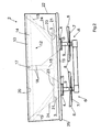
- the centrifugal fertilizer broadcaster has the frame 1 and the storage container 2 with the adjoining discharge funnels 3, the lower ends 4 are each assigned a metering device 5, on.
- the metering device 5 directs the material in the storage container 2 in adjustable amounts of the metering device 5 arranged below the rotating and driven distributor 6, which is designed as a centrifugal disc 7 with thereon arranged throwing blades 8 to.
- the frame 1 has a front portion 9 on which the three-point coupling elements 10 are arranged for attachment to the three-point power lift of a tractor.
- the distributor 6 is arranged at the lower cross member 11 of the frame 1, the distributor 6 is arranged.
- the frame 1 has in the upper area 12 a peripheral support area 13.
- the support area 13 is aligned substantially horizontally.
- the horizontal support portion 13 forming frame members 14 are additionally supported by obliquely extending struts 15 relative to the front frame part 9.
- the frame 1 in its center a running in the direction of travel 16 of the centrifugal spreader and the reservoir 2 in the middle supporting the longitudinal beam 17.
- the roof-shaped central portion 18 of the reservoir 2 is supported resting on the longitudinal beam 17.
- support elements 19 are arranged on the frame 1, to which the discharge funnels 3 are fastened with the respectively associated metering element 5 independently of the storage container 2 on the frame 1.
- the reservoir 2 has in its upper region 20 with the support portion 13 of the frame 1 cooperating Supporting regions 14 on.
- the support region 14 of the storage container 2 rests on the support region 13 of the frame 1.
- the lower ends 21 of the reservoir 2 open into the outlet funnel 3 in an overlapping manner.
- the lower ends 21 of the storage container 2 are not connected to the discharge funnels 3. As a result, the storage container 2 can move relative to the discharge funnels 3.
- the storage container 2 has outer wall portions 22 covering the storage container 2.
- the reservoir 2 consists of an inner, funnel-shaped and the materials to be distributed receiving and in the outlet funnel 3, which carry the metering 5, opening area 23 and an outer, partially covering the frame 1 and the reservoir 2 stiffening and lining wall portions 22
- the outer cladding wall portion 22 is formed integrally with the funnel-shaped portion 24 of the reservoir 2 and thus connected to the reservoir portion 24.
- the outer cladding wall portion 22 and the reservoir portion 24 are integrally made of plastic, while the discharge funnel 3 and the frame 1 are made of metal.
- the storage container 2 has in each case with its inner and outer wall portions 22 at least in the lateral and the lower region in longitudinal section on a downwardly open V-shaped or U-shaped cross-section, as shown in particular in FIG. 3.
- FIGS. 1-5 show the frame 1 and the reservoir 2 consist of separate parts
- the reservoir 2 is placed over the frame 1 of FIG. 5 and so the lower ends 21 of the funnel-shaped portion 24 of the reservoir 2 in the on Frame 1 arranged discharge funnel 3 overlap opening.
- the reservoir 2 is attached to the frame 1, this can be done for example with screws, not shown, clips or other suitable fasteners.
- the outer cladding wall portion 22 is formed as the outer orbits of the distribution elements 8 superior protection element 25, as Figs. 1-3 show.
- the wall region 22 covering the storage container 2 not only fulfills its cladding function but also a protective function in which the protective element 25 projecting the distribution elements 8 is arranged in an integrated manner, as it were, in the element forming the cladding wall regions 22.
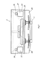
- the centrifugal fertilizer broadcaster according to FIGS. 6 and 7 differs from the centrifugal fertilizer broadcaster according to FIGS. 1-5 in that ladder-like ascending elements 25 are arranged in an integrated manner on the side in the wall element 22 covering the reservoir 2. Furthermore, lighting devices 26 and warning panels 27 are arranged in an integrated manner on the rear side in the wall elements 22 covering the storage container 2. The leading to the lighting devices 26 lines are laid in a manner not shown in an integrated manner to the outer cladding wall portions 22 in a hidden manner.
- outer wall portions 22 lining the frame 1 are arranged on the front side of the centrifugal fertilizer spreader in an integrated manner as wall straps 28 serving as dirt traps.
- the frame 1 clad wall portions 22 in an integrated manner at least one container-like receptacle for receiving accessories, replacement parts, etc. may be arranged.
- a container receptacle is closed in a manner not shown with a cover.
- the bottom of such a container-like receptacle is inclined sloping inwards.
- the frame 1 clad wall portions 22 in an integrated manner at least one walk-platform or a walk-in element similar to the ladder-like rise openings 25 may be arranged. Also, such a walk-platform can overhang the container 2 facing elements 22 to the outside.
- the centrifugal fertilizer broadcaster according to FIG. 8 differs from the centrifugal fertilizer broadcaster according to FIGS. 1-7 in that the outlet funnels 29 are not arranged as separate elements on the frame 30, but by means of flange elements 31 at the lower ends 32 of the funnel-shaped regions 33 of the reservoir 34 are flanged.
- the parts of the reservoir 34 are made of plastic, while the frame 30 and the outlet funnel 29 are made of metal.
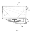
- the centrifugal fertilizer broadcaster according to FIG. 9 differs from the centrifugal fertilizer broadcaster according to FIGS. 1-5 in that the outlet funnels 35 are part of the funnel-shaped regions 36 of the reservoir 37 in an integrated manner and are integrally connected thereto.
- the outlet funnel 35 as well as the reservoir 37 made of plastic, while the frame parts 38 are made of metal.
- the centrifugal fertilizer spreader according to FIG. 10 has a frame 39 and the storage container 40 with the adjoining discharge funnels 41, whose lower ends 4 are each assigned a metering device 5.
- the metering device 5 directs the material located in the reservoir in adjustable amounts of the arranged below the metering device 5 and rotatably driven distributor 6, which is designed as a centrifugal disc 7 with thereon arranged throwing blades 8 to.
- the frame 39 has a front portion 9, on which the three-point coupling elements 10 are arranged for attachment to the three-point hitch of a tractor.
- the frame 39 has rearwardly projecting trusses to which the discharge funnels are attached.
- the discharge funnels have an upper flange, on which by means of a flange of the reservoir is attached.
- the frame and the outlet funnels are made of metal and the reservoir is made of plastic.
Landscapes
- Life Sciences & Earth Sciences (AREA)
- Soil Sciences (AREA)
- Environmental Sciences (AREA)
- Fertilizing (AREA)
Applications Claiming Priority (1)
| Application Number | Priority Date | Filing Date | Title |
|---|---|---|---|
| DE200610019477 DE102006019477A1 (de) | 2006-04-26 | 2006-04-26 | Vorrichtung zum Streuen körniger Stoffe |
Publications (2)
| Publication Number | Publication Date |
|---|---|
| EP1849344A2 true EP1849344A2 (fr) | 2007-10-31 |
| EP1849344A3 EP1849344A3 (fr) | 2008-06-04 |
Family
ID=38293089
Family Applications (1)
| Application Number | Title | Priority Date | Filing Date |
|---|---|---|---|
| EP07008074A Withdrawn EP1849344A3 (fr) | 2006-04-26 | 2007-04-20 | Dispositif de commande de matières granuleuses |
Country Status (2)
| Country | Link |
|---|---|
| EP (1) | EP1849344A3 (fr) |
| DE (1) | DE102006019477A1 (fr) |
Cited By (1)
| Publication number | Priority date | Publication date | Assignee | Title |
|---|---|---|---|---|
| CN105836129A (zh) * | 2016-03-21 | 2016-08-10 | 中国农业大学 | 一种农用播撒无人机 |
Families Citing this family (2)
| Publication number | Priority date | Publication date | Assignee | Title |
|---|---|---|---|---|
| CN103688636B (zh) * | 2013-12-13 | 2015-11-18 | 安徽灵杨农机制造有限公司 | 撒肥机构 |
| CN105453783A (zh) * | 2016-01-20 | 2016-04-06 | 钟国平 | 一种离心式农田施肥机 |
Family Cites Families (6)
| Publication number | Priority date | Publication date | Assignee | Title |
|---|---|---|---|---|
| NL8006454A (nl) * | 1980-11-27 | 1982-06-16 | Lely Nv C Van Der | Inrichting voor het verspreiden van korrel- en/of poedervormig materiaal. |
| NL8901903A (nl) * | 1989-07-24 | 1991-02-18 | Lely Nv C Van Der | Machine voor het verspreiden van materiaal. |
| DE19620830C2 (de) * | 1995-06-17 | 2002-05-16 | Rauch Landmaschfab Gmbh | Sämaschine mit einem trichterförmigen Saatgut-Behälter |
| US6116552A (en) * | 1998-08-12 | 2000-09-12 | Deere Company | Reinforced plastic tank support |
| DE19939169A1 (de) * | 1999-08-20 | 2001-02-22 | Amazonen Werke Dreyer H | Schleuderdüngerstreuer |
| AU2002354226A1 (en) * | 2002-12-04 | 2004-06-23 | Officine Cavallo Srl | An apparatus for spreading a granular product |
-
2006
- 2006-04-26 DE DE200610019477 patent/DE102006019477A1/de not_active Withdrawn
-
2007
- 2007-04-20 EP EP07008074A patent/EP1849344A3/fr not_active Withdrawn
Cited By (1)
| Publication number | Priority date | Publication date | Assignee | Title |
|---|---|---|---|---|
| CN105836129A (zh) * | 2016-03-21 | 2016-08-10 | 中国农业大学 | 一种农用播撒无人机 |
Also Published As
| Publication number | Publication date |
|---|---|
| DE102006019477A1 (de) | 2007-10-31 |
| EP1849344A3 (fr) | 2008-06-04 |
Similar Documents
| Publication | Publication Date | Title |
|---|---|---|
| DE112008003447T5 (de) | Abdeckungsanordnung und zugehöriges Verfahren | |
| EP1849345B1 (fr) | Dispositif pour l'épandage de matières granuleuses | |
| DE2954406C2 (fr) | ||
| EP1849344A2 (fr) | Dispositif de commande de matières granuleuses | |
| DE1757862C3 (de) | Streugerät für körniges oder pulvriges Material. Ausscheidung aus: 1457835 | |
| DE102005034281B4 (de) | Zweischeibenstreuer mit einem Streugut-Behälter | |
| DE2008016A1 (de) | Landwirtschaftliches Gerät | |
| EP2353359B1 (fr) | Dispositif agricole | |
| EP1593296B1 (fr) | Dispositif d'épandage, spécialement pour la distribution de grains fins ou grossiers d'engrais minéral | |
| EP0344522B1 (fr) | Dispositif pour épandre du matériau granulé spécialement engrais | |
| DE102020125237A1 (de) | Siebvorrichtung | |
| DE19733549B4 (de) | Zweischeiben-Schleuderstreuer | |
| EP2353360B1 (fr) | Epandeur centrifuge | |
| DE1905745C3 (de) | Landwirtschaftliches Streugerät für körniges oder pulvriges Streugut | |
| EP2116122B1 (fr) | Epandeur à disques | |
| DE102010000298A1 (de) | Zweischeibenstreuer | |
| EP3979781B1 (fr) | Machine de distribution pneumatique de semence ou engrais | |
| DE102012107897A1 (de) | Selbstfahrende landwirtschaftliche Arbeitsmaschine | |
| DE2421094A1 (de) | Zusatzgeraet fuer einen schleuderduengerstreuer | |
| EP4736619A1 (fr) | Machine de distribution agricole dotée d'un système de réservoir modulaire | |
| AT401539B (de) | Einrichtung für selbstfahrende bagger | |
| DE9115220U1 (de) | Vorrichtung zum Entsorgen von flüssigen Medien | |
| EP1900270A1 (fr) | Machine agricole automobile | |
| DE2037446A1 (de) | Mähdrescher | |
| DE1981010U (de) | Mehrzweck-verteilvorrichtung als anbaugeraet fuer landwirtschaftliche maschinen. |
Legal Events
| Date | Code | Title | Description |
|---|---|---|---|
| PUAI | Public reference made under article 153(3) epc to a published international application that has entered the european phase |
Free format text: ORIGINAL CODE: 0009012 |
|
| AK | Designated contracting states |
Kind code of ref document: A2 Designated state(s): AT BE BG CH CY CZ DE DK EE ES FI FR GB GR HU IE IS IT LI LT LU LV MC MT NL PL PT RO SE SI SK TR |
|
| AX | Request for extension of the european patent |
Extension state: AL BA HR MK YU |
|
| PUAL | Search report despatched |
Free format text: ORIGINAL CODE: 0009013 |
|
| AK | Designated contracting states |
Kind code of ref document: A3 Designated state(s): AT BE BG CH CY CZ DE DK EE ES FI FR GB GR HU IE IS IT LI LT LU LV MC MT NL PL PT RO SE SI SK TR |
|
| AX | Request for extension of the european patent |
Extension state: AL BA HR MK RS |
|
| 17P | Request for examination filed |
Effective date: 20081126 |
|
| 17Q | First examination report despatched |
Effective date: 20090112 |
|
| AKX | Designation fees paid |
Designated state(s): AT BE BG CH CY CZ DE DK EE ES FI FR GB GR HU IE IS IT LI LT LU LV MC MT NL PL PT RO SE SI SK TR |
|
| STAA | Information on the status of an ep patent application or granted ep patent |
Free format text: STATUS: THE APPLICATION IS DEEMED TO BE WITHDRAWN |
|
| 18D | Application deemed to be withdrawn |
Effective date: 20090526 |