EP1849596A1 - Verfahren zur herstellung eines verbundkunststoffflächengebildes, verbundkunststoffflächengebilde und aus dem verbundkunststoffflächengebilde hergestellte rückenlehne eines sitzes - Google Patents
Verfahren zur herstellung eines verbundkunststoffflächengebildes, verbundkunststoffflächengebilde und aus dem verbundkunststoffflächengebilde hergestellte rückenlehne eines sitzes Download PDFInfo
- Publication number
- EP1849596A1 EP1849596A1 EP05792094A EP05792094A EP1849596A1 EP 1849596 A1 EP1849596 A1 EP 1849596A1 EP 05792094 A EP05792094 A EP 05792094A EP 05792094 A EP05792094 A EP 05792094A EP 1849596 A1 EP1849596 A1 EP 1849596A1
- Authority
- EP
- European Patent Office
- Prior art keywords
- board
- upper cover
- nether
- soleplate
- cover board
- Prior art date
- Legal status (The legal status is an assumption and is not a legal conclusion. Google has not performed a legal analysis and makes no representation as to the accuracy of the status listed.)
- Withdrawn
Links
Images


Classifications
-
- B—PERFORMING OPERATIONS; TRANSPORTING
- B29—WORKING OF PLASTICS; WORKING OF SUBSTANCES IN A PLASTIC STATE IN GENERAL
- B29C—SHAPING OR JOINING OF PLASTICS; SHAPING OF MATERIAL IN A PLASTIC STATE, NOT OTHERWISE PROVIDED FOR; AFTER-TREATMENT OF THE SHAPED PRODUCTS, e.g. REPAIRING
- B29C65/00—Joining or sealing of preformed parts, e.g. welding of plastics materials; Apparatus therefor
- B29C65/56—Joining or sealing of preformed parts, e.g. welding of plastics materials; Apparatus therefor using mechanical means or mechanical connections, e.g. form-fits
- B29C65/58—Snap connection
-
- A—HUMAN NECESSITIES
- A47—FURNITURE; DOMESTIC ARTICLES OR APPLIANCES; COFFEE MILLS; SPICE MILLS; SUCTION CLEANERS IN GENERAL
- A47C—CHAIRS; SOFAS; BEDS
- A47C7/00—Parts, details, or accessories of chairs or stools
-
- B—PERFORMING OPERATIONS; TRANSPORTING
- B29—WORKING OF PLASTICS; WORKING OF SUBSTANCES IN A PLASTIC STATE IN GENERAL
- B29C—SHAPING OR JOINING OF PLASTICS; SHAPING OF MATERIAL IN A PLASTIC STATE, NOT OTHERWISE PROVIDED FOR; AFTER-TREATMENT OF THE SHAPED PRODUCTS, e.g. REPAIRING
- B29C65/00—Joining or sealing of preformed parts, e.g. welding of plastics materials; Apparatus therefor
- B29C65/48—Joining or sealing of preformed parts, e.g. welding of plastics materials; Apparatus therefor using adhesives, i.e. using supplementary joining material; solvent bonding
-
- B—PERFORMING OPERATIONS; TRANSPORTING
- B29—WORKING OF PLASTICS; WORKING OF SUBSTANCES IN A PLASTIC STATE IN GENERAL
- B29C—SHAPING OR JOINING OF PLASTICS; SHAPING OF MATERIAL IN A PLASTIC STATE, NOT OTHERWISE PROVIDED FOR; AFTER-TREATMENT OF THE SHAPED PRODUCTS, e.g. REPAIRING
- B29C65/00—Joining or sealing of preformed parts, e.g. welding of plastics materials; Apparatus therefor
- B29C65/56—Joining or sealing of preformed parts, e.g. welding of plastics materials; Apparatus therefor using mechanical means or mechanical connections, e.g. form-fits
- B29C65/562—Joining or sealing of preformed parts, e.g. welding of plastics materials; Apparatus therefor using mechanical means or mechanical connections, e.g. form-fits using extra joining elements, i.e. which are not integral with the parts to be joined
-
- B—PERFORMING OPERATIONS; TRANSPORTING
- B29—WORKING OF PLASTICS; WORKING OF SUBSTANCES IN A PLASTIC STATE IN GENERAL
- B29C—SHAPING OR JOINING OF PLASTICS; SHAPING OF MATERIAL IN A PLASTIC STATE, NOT OTHERWISE PROVIDED FOR; AFTER-TREATMENT OF THE SHAPED PRODUCTS, e.g. REPAIRING
- B29C66/00—General aspects of processes or apparatus for joining preformed parts
- B29C66/01—General aspects dealing with the joint area or with the area to be joined
- B29C66/05—Particular design of joint configurations
- B29C66/10—Particular design of joint configurations particular design of the joint cross-sections
- B29C66/12—Joint cross-sections combining only two joint-segments; Tongue and groove joints; Tenon and mortise joints; Stepped joint cross-sections
- B29C66/122—Joint cross-sections combining only two joint-segments, i.e. one of the parts to be joined comprising only two joint-segments in the joint cross-section
- B29C66/1222—Joint cross-sections combining only two joint-segments, i.e. one of the parts to be joined comprising only two joint-segments in the joint cross-section comprising at least a lapped joint-segment
-
- B—PERFORMING OPERATIONS; TRANSPORTING
- B29—WORKING OF PLASTICS; WORKING OF SUBSTANCES IN A PLASTIC STATE IN GENERAL
- B29C—SHAPING OR JOINING OF PLASTICS; SHAPING OF MATERIAL IN A PLASTIC STATE, NOT OTHERWISE PROVIDED FOR; AFTER-TREATMENT OF THE SHAPED PRODUCTS, e.g. REPAIRING
- B29C66/00—General aspects of processes or apparatus for joining preformed parts
- B29C66/01—General aspects dealing with the joint area or with the area to be joined
- B29C66/05—Particular design of joint configurations
- B29C66/10—Particular design of joint configurations particular design of the joint cross-sections
- B29C66/12—Joint cross-sections combining only two joint-segments; Tongue and groove joints; Tenon and mortise joints; Stepped joint cross-sections
- B29C66/122—Joint cross-sections combining only two joint-segments, i.e. one of the parts to be joined comprising only two joint-segments in the joint cross-section
- B29C66/1224—Joint cross-sections combining only two joint-segments, i.e. one of the parts to be joined comprising only two joint-segments in the joint cross-section comprising at least a butt joint-segment
-
- B—PERFORMING OPERATIONS; TRANSPORTING
- B29—WORKING OF PLASTICS; WORKING OF SUBSTANCES IN A PLASTIC STATE IN GENERAL
- B29C—SHAPING OR JOINING OF PLASTICS; SHAPING OF MATERIAL IN A PLASTIC STATE, NOT OTHERWISE PROVIDED FOR; AFTER-TREATMENT OF THE SHAPED PRODUCTS, e.g. REPAIRING
- B29C66/00—General aspects of processes or apparatus for joining preformed parts
- B29C66/01—General aspects dealing with the joint area or with the area to be joined
- B29C66/05—Particular design of joint configurations
- B29C66/10—Particular design of joint configurations particular design of the joint cross-sections
- B29C66/12—Joint cross-sections combining only two joint-segments; Tongue and groove joints; Tenon and mortise joints; Stepped joint cross-sections
- B29C66/124—Tongue and groove joints
- B29C66/1244—Tongue and groove joints characterised by the male part, i.e. the part comprising the tongue
- B29C66/12441—Tongue and groove joints characterised by the male part, i.e. the part comprising the tongue being a single wall
-
- B—PERFORMING OPERATIONS; TRANSPORTING
- B29—WORKING OF PLASTICS; WORKING OF SUBSTANCES IN A PLASTIC STATE IN GENERAL
- B29C—SHAPING OR JOINING OF PLASTICS; SHAPING OF MATERIAL IN A PLASTIC STATE, NOT OTHERWISE PROVIDED FOR; AFTER-TREATMENT OF THE SHAPED PRODUCTS, e.g. REPAIRING
- B29C66/00—General aspects of processes or apparatus for joining preformed parts
- B29C66/01—General aspects dealing with the joint area or with the area to be joined
- B29C66/05—Particular design of joint configurations
- B29C66/10—Particular design of joint configurations particular design of the joint cross-sections
- B29C66/12—Joint cross-sections combining only two joint-segments; Tongue and groove joints; Tenon and mortise joints; Stepped joint cross-sections
- B29C66/124—Tongue and groove joints
- B29C66/1246—Tongue and groove joints characterised by the female part, i.e. the part comprising the groove
- B29C66/12469—Tongue and groove joints characterised by the female part, i.e. the part comprising the groove being asymmetric
-
- B—PERFORMING OPERATIONS; TRANSPORTING
- B29—WORKING OF PLASTICS; WORKING OF SUBSTANCES IN A PLASTIC STATE IN GENERAL
- B29C—SHAPING OR JOINING OF PLASTICS; SHAPING OF MATERIAL IN A PLASTIC STATE, NOT OTHERWISE PROVIDED FOR; AFTER-TREATMENT OF THE SHAPED PRODUCTS, e.g. REPAIRING
- B29C66/00—General aspects of processes or apparatus for joining preformed parts
- B29C66/50—General aspects of joining tubular articles; General aspects of joining long products, i.e. bars or profiled elements; General aspects of joining single elements to tubular articles, hollow articles or bars; General aspects of joining several hollow-preforms to form hollow or tubular articles
- B29C66/51—Joining tubular articles, profiled elements or bars; Joining single elements to tubular articles, hollow articles or bars; Joining several hollow-preforms to form hollow or tubular articles
- B29C66/54—Joining several hollow-preforms, e.g. half-shells, to form hollow articles, e.g. for making balls, containers; Joining several hollow-preforms, e.g. half-cylinders, to form tubular articles
-
- B—PERFORMING OPERATIONS; TRANSPORTING
- B29—WORKING OF PLASTICS; WORKING OF SUBSTANCES IN A PLASTIC STATE IN GENERAL
- B29C—SHAPING OR JOINING OF PLASTICS; SHAPING OF MATERIAL IN A PLASTIC STATE, NOT OTHERWISE PROVIDED FOR; AFTER-TREATMENT OF THE SHAPED PRODUCTS, e.g. REPAIRING
- B29C66/00—General aspects of processes or apparatus for joining preformed parts
- B29C66/70—General aspects of processes or apparatus for joining preformed parts characterised by the composition, physical properties or the structure of the material of the parts to be joined; Joining with non-plastics material
- B29C66/72—General aspects of processes or apparatus for joining preformed parts characterised by the composition, physical properties or the structure of the material of the parts to be joined; Joining with non-plastics material characterised by the structure of the material of the parts to be joined
- B29C66/723—General aspects of processes or apparatus for joining preformed parts characterised by the composition, physical properties or the structure of the material of the parts to be joined; Joining with non-plastics material characterised by the structure of the material of the parts to be joined being multi-layered
-
- B—PERFORMING OPERATIONS; TRANSPORTING
- B32—LAYERED PRODUCTS
- B32B—LAYERED PRODUCTS, i.e. PRODUCTS BUILT-UP OF STRATA OF FLAT OR NON-FLAT, e.g. CELLULAR OR HONEYCOMB, FORM
- B32B27/00—Layered products comprising a layer of synthetic resin
- B32B27/06—Layered products comprising a layer of synthetic resin as the main or only constituent of a layer, which is next to another layer of the same or of a different material
- B32B27/08—Layered products comprising a layer of synthetic resin as the main or only constituent of a layer, which is next to another layer of the same or of a different material of synthetic resin
-
- B—PERFORMING OPERATIONS; TRANSPORTING
- B32—LAYERED PRODUCTS
- B32B—LAYERED PRODUCTS, i.e. PRODUCTS BUILT-UP OF STRATA OF FLAT OR NON-FLAT, e.g. CELLULAR OR HONEYCOMB, FORM
- B32B3/00—Layered products comprising a layer with external or internal discontinuities or unevennesses, or a layer of non-planar shape; Layered products comprising a layer having particular features of form
- B32B3/02—Layered products comprising a layer with external or internal discontinuities or unevennesses, or a layer of non-planar shape; Layered products comprising a layer having particular features of form characterised by features of form at particular places, e.g. in edge regions
- B32B3/06—Layered products comprising a layer with external or internal discontinuities or unevennesses, or a layer of non-planar shape; Layered products comprising a layer having particular features of form characterised by features of form at particular places, e.g. in edge regions for securing layers together; for attaching the product to another member, e.g. to a support, or to another product, e.g. groove/tongue, interlocking
-
- B—PERFORMING OPERATIONS; TRANSPORTING
- B32—LAYERED PRODUCTS
- B32B—LAYERED PRODUCTS, i.e. PRODUCTS BUILT-UP OF STRATA OF FLAT OR NON-FLAT, e.g. CELLULAR OR HONEYCOMB, FORM
- B32B7/00—Layered products characterised by the relation between layers; Layered products characterised by the relative orientation of features between layers, or by the relative values of a measurable parameter between layers, i.e. products comprising layers having different physical, chemical or physicochemical properties; Layered products characterised by the interconnection of layers
- B32B7/04—Interconnection of layers
-
- B—PERFORMING OPERATIONS; TRANSPORTING
- B29—WORKING OF PLASTICS; WORKING OF SUBSTANCES IN A PLASTIC STATE IN GENERAL
- B29C—SHAPING OR JOINING OF PLASTICS; SHAPING OF MATERIAL IN A PLASTIC STATE, NOT OTHERWISE PROVIDED FOR; AFTER-TREATMENT OF THE SHAPED PRODUCTS, e.g. REPAIRING
- B29C65/00—Joining or sealing of preformed parts, e.g. welding of plastics materials; Apparatus therefor
- B29C65/02—Joining or sealing of preformed parts, e.g. welding of plastics materials; Apparatus therefor by heating, with or without pressure
- B29C65/08—Joining or sealing of preformed parts, e.g. welding of plastics materials; Apparatus therefor by heating, with or without pressure using ultrasonic vibrations
-
- B—PERFORMING OPERATIONS; TRANSPORTING
- B29—WORKING OF PLASTICS; WORKING OF SUBSTANCES IN A PLASTIC STATE IN GENERAL
- B29C—SHAPING OR JOINING OF PLASTICS; SHAPING OF MATERIAL IN A PLASTIC STATE, NOT OTHERWISE PROVIDED FOR; AFTER-TREATMENT OF THE SHAPED PRODUCTS, e.g. REPAIRING
- B29C66/00—General aspects of processes or apparatus for joining preformed parts
- B29C66/70—General aspects of processes or apparatus for joining preformed parts characterised by the composition, physical properties or the structure of the material of the parts to be joined; Joining with non-plastics material
- B29C66/71—General aspects of processes or apparatus for joining preformed parts characterised by the composition, physical properties or the structure of the material of the parts to be joined; Joining with non-plastics material characterised by the composition of the plastics material of the parts to be joined
-
- B—PERFORMING OPERATIONS; TRANSPORTING
- B29—WORKING OF PLASTICS; WORKING OF SUBSTANCES IN A PLASTIC STATE IN GENERAL
- B29L—INDEXING SCHEME ASSOCIATED WITH SUBCLASS B29C, RELATING TO PARTICULAR ARTICLES
- B29L2024/00—Articles with hollow walls
- B29L2024/006—Articles with hollow walls multi-channelled
-
- B—PERFORMING OPERATIONS; TRANSPORTING
- B29—WORKING OF PLASTICS; WORKING OF SUBSTANCES IN A PLASTIC STATE IN GENERAL
- B29L—INDEXING SCHEME ASSOCIATED WITH SUBCLASS B29C, RELATING TO PARTICULAR ARTICLES
- B29L2031/00—Other particular articles
- B29L2031/44—Furniture or parts thereof
- B29L2031/443—Chairs
-
- B—PERFORMING OPERATIONS; TRANSPORTING
- B32—LAYERED PRODUCTS
- B32B—LAYERED PRODUCTS, i.e. PRODUCTS BUILT-UP OF STRATA OF FLAT OR NON-FLAT, e.g. CELLULAR OR HONEYCOMB, FORM
- B32B2307/00—Properties of the layers or laminate
- B32B2307/70—Other properties
- B32B2307/718—Weight, e.g. weight per square meter
-
- B—PERFORMING OPERATIONS; TRANSPORTING
- B32—LAYERED PRODUCTS
- B32B—LAYERED PRODUCTS, i.e. PRODUCTS BUILT-UP OF STRATA OF FLAT OR NON-FLAT, e.g. CELLULAR OR HONEYCOMB, FORM
- B32B2479/00—Furniture
-
- Y—GENERAL TAGGING OF NEW TECHNOLOGICAL DEVELOPMENTS; GENERAL TAGGING OF CROSS-SECTIONAL TECHNOLOGIES SPANNING OVER SEVERAL SECTIONS OF THE IPC; TECHNICAL SUBJECTS COVERED BY FORMER USPC CROSS-REFERENCE ART COLLECTIONS [XRACs] AND DIGESTS
- Y10—TECHNICAL SUBJECTS COVERED BY FORMER USPC
- Y10T—TECHNICAL SUBJECTS COVERED BY FORMER US CLASSIFICATION
- Y10T428/00—Stock material or miscellaneous articles
- Y10T428/13—Hollow or container type article [e.g., tube, vase, etc.]
- Y10T428/1352—Polymer or resin containing [i.e., natural or synthetic]
Definitions
- the present invention relates to a plastic composite board and its manufacturing method.
- the Chinese patent application number 96120421.4 discloses a plastic hollow plate for postal packing chest and its production technology; the plastic hollow plate is made up of polyethylene or polypropylene and pigment through extruding-out, and has an internal hollow structure with vertical reinforcing ribs at intervals, and has equidistant vertical reinforcement pieces in the vertical direction with the plane. Its advantages include no poison and odour, high strength and shock and corrosion resistances, light, weight, and long service life. But the plastic hollow plate is only fit to plane plate, such as box body; the plastic hollow plate can not be used as special shape, such as backrest of chair or seat board and so on.
- It has another board of blow molding or board of vacuum forming technology, which also can be made as hollow board with some reinforcement pieces on its lower faceplate for improving its bearing power; the lower faceplate of the board is scraggy, so the board can not be used as double sided board, such as backrest of chair.
- the purpose of the present invention is to overcome the disadvantages of the known technology, and to supply a plastic composite board and its manufacturing method; the plastic composite board can be made to board of curved surface with any shape, and has a light weight, a high strength, low manufacturing cost, and can be used as double sided board.
- the manufacturing method of the plastic composite board of the present invention adopts technique proposal as follows: the manufacturing method of a plastic composite board, comprising
- a plastic composite board of the present invention comprises a composite upper cover board and a composite nether soleplate;
- the upper cover board is board of curved surface or surface board, which is made by direct vacuum forming technology according to the desired shape of the plastic composite board;
- the edge of the upper cover board extends downwards to form a suberect connective wall;
- the nether soleplate is directly made by injection moulding according to the desired shape of the plastic composite board.
- the undersurface of the nether soleplate is glaze; the upper surface of the nether soleplate is molded with some reinforcement pieces.
- the top surface constituted by reinforcement pieces is matched with the bottom surface of the upper cover board.
- the edge of the nether soleplate extends upwards to form a suberect connective wall.
- the connective wall of the upper cover board is fixed to the connective wall of the nether soleplate to form a closed composite board; the top surface of every reinforcement pieces is located under the bottom surface of the upper cover board and every reinforcement pieces areis located inside of the composite board.
- the undersurface of said nether soleplate is plane or curved surface.
- Said upper cover board buckles on the nether soleplate; the connective wall of the upper cover board is fixed to the connective wall of the nether soleplate by gluewater, welding, buckling joint or screw thread.
- the upper surface of said every reinforcement pieces is fixed to the bottom surface of the upper cover board by gluewater or ultrasonic jointing.
- the upper surface of said upper cover board is composite with film layer; the film layer is design of grain of wood or marble or other natural objects.
- the bottom of the outside of the connective wall of said nether soleplate has an orientation protruding part; the width of the protruding part 15 is equal to the thickness of the connective wall of the upper cover board.
- the bottom of the outside of the connective wall of said nether soleplate extends outside to form an orientation slot; the width of the orientation slot is equal to the thickness of the connective wall of the upper cover board.
- Said upper cover board is fixed to the nether soleplate by bolt and matched threaded hole, or by bolt and matched inner nut.
- the present invention has virtues as follows:
- plastic board of required shape is directly made by vacuum forming technology as the upper cover board; plastic board of required shape is directly made by injection moulding as the nether soleplate with some reinforcement pieces, the top surface constituted by some reinforcement pieces is matched with the bottom surface of the upper cover board; as the upper cover board and the nether soleplate of the present invention separately adopts vacuum forming technology and injection moulding, which to make the plastic composite board have the virtue of light weight of board of vacuum forming technology, and have the virtue of high strength of board of injection moulding; and that, the upper surface of the upper cover board can be composite with film layer, the undersurface of the nether soleplate can be slick plane or slick curved surface; so the plastic composite board can directly replace curved wood board or solid wood board (such as replacing curved wood board and solid wood board as the backrest and seat board of chair), and it has lighter weigh than the curved wood board or solid wood board, has a higher strength than the curved wood board or the solid wood board, has a more
- the present invention has virtues as follows:
- the upper cover board of the plastic composite board of the present invention is made by direct vacuum forming technology according to desired shape of the upper surface of the plastic composite board, which is machined easily, has a high precision of machining, has a light weight and a high strength and a low manufacturing cost;
- the nether soleplate is made by direct injection moulding according to the desired shape of the plastic composite board, which is machined easily, has a high precision of machining, has a high strength and a low manufacturing cost.
- the top surface constituted by reinforcement pieces is matched with the bottom surface of the upper cover board, and the undersurface of the upper cover board leans against the upper surface of every reinforcement pieces, and every reinforcement pieces support the upper cover board; every reinforcement pieces increase the strength of the undersurface, and increase the strength of the nether soleplate, and increase the strength of the plastic composite board.
- the upper cover board buckles on the undersurface of the nether soleplate; the upper cover board is fixed to the nether soleplate by gluewater, welding, buckling joint or screw thread, which has a convenient connection and has a high connection intensity.
- the upper surface of every reinforcement pieces is fixed to the bottom surface of the upper cover board by gluewater or ultrasonic jointing, which has a high connection intensity and is machined expediently, and increase the matched intensity of the upper cover board and the nether soleplate, and increase the intensity of the whole plastic composite board.
- the upper cover board is fixed to the nether soleplate by inserting the elasticity hooks into the holes or grooves through outside force, which has a convenient connection and a high connection intensity and is knock-down.
- the upper cover board is fixed to the nether soleplate by bolt and matched threaded hole, or by bolt and matched inner nut, which has a highhigh connection intensity and is knock-down.
- a plastic composite board as shown in figure 2, comprising the composite upper cover board 10 and the composite nether soleplate 12.
- the upper cover board 10 is board of curved surface or surface board, which is made by direct vacuum forming technology according to the desired shape of the plastic composite board; the nether soleplate 12 is directly made by injection moulding according to the desired shape of the plastic composite board.
- the undersurface 14 of the nether soleplate 12 is glaze; the upper surface of the nether soleplate 12 is molded with some integrative reinforcement pieces 16.
- the top surface constituted by reinforcement pieces 16 is matched with the bottom surface of the upper cover board 10.
- every reinforcement pieces 16 is located under the bottom surface of the upper cover board 10; every reinforcement pieces 16 are located between the upper cover board 10 and the nether soleplate 12, namely the upper cover board 10 is fixed to the nether soleplate 12 to form a close composite board.
- Some reinforcement pieces 16 are located on the upper surface of the nether soleplate 12 regularly; the number of reinforcement pieces 16 is designed by the area and the height of the plastic composite board and the intensity demand of the design.
- both the upper surface of the upper cover board 10 and the undersurface 14 of the soleplate 12 are printed with printing layer 18; the printing layer 18 is design of grain of wood or marble or other natural objects.
- the upper cover board 10 is single-layer plastic board or multi-layer plastic board made by vacuum forming technology; the height of the plastic board varied from 0.3 to 4 mm.
- the plastic composite board has a beautiful appearance and a thin thickness.
- the materials of the upper cover board 10 are all PP, PE, ABS or other engineering plastics.
- the upper cover board 10 of the present invention is fixed to the nether soleplate 12 by modes as follows:
- the top surface of reinforcement pieces 16 is fixed to the bottom surface of the upper cover board 10 by gluewater or ultrasonic jointing.
- the upper surface constituted of every reinforcement pieces 16 fits into the bottom surface of the upper cover board; the upper cover board 10 is fixed to the nether soleplate 12 to form a close composite board; every reinforcement pieces 16 locate in the composite board.
- the top surfaces of every reinforcement pieces 16 fits into the corresponding parts of the bottom surface of the upper cover board 10.
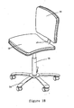
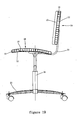
- Embodiment 1 a swivel chair, as shown in figures 18 and 19, comprising a base 24, a leg brace 26, a seat board 28, a backrest 30 and a connective pole 32.
- the base 24 comprises a pedestal and five feet bars which is fixed to the pedestal equably; feet bars have universal idler wheels, so the base 24 can move.
- the leg brace 26 is fixed to the center of the pedestal; the leg brace 26 comprises a sleeve, a touring bar which has bell and spigot joint with the sleeve, a lifter set locating between the sleeve and the touring bar, a governor lever for accommodating the lifter set. It can accommodate the height of the leg brace 26 by accommodating the lift and fall of the touring bar.
- Early seat board 28 and backrest 30 are made by curvedbent wood board or solid wood board, which has a big weight and wastes wood materials.
- the seat board 28 and the backrest 30 of the present invention adopt the above plastic composite board, which has a light weight, a good strength, an appropriate curved surface of outer surface, and can be printed with grain of wood or marbling according to the require of people.
- the seat board 28 is board of curved surface with convex upper part, comprises the upper cover board 10 of curved surface with convex upper part made by vacuum forming technology; the circumambience of the upper cover board 10 extends downwards to form a suberect connective wall 11; a nether soleplate 12 made by injection moulding.
- the undersurface 14 of the nether soleplate 12 is glaze; the upper surface of the nether soleplate 12 is molded with some integrative reinforcement pieces 16.
- the top surface constituted by reinforcement pieces 16 is matched with the bottom surface of the upper cover board 10.
- the circumambience of the nether soleplate 12 extends upwards to form a suberect connective wall 13.
- the upper cover board 10 buckles on the nether soleplate 12; every reinforcement pieces 16 are locate between the upper cover board 10 and the nether soleplate 12.
- the top surface of reinforcement pieces 16 is fixed to the bottom surface of the upper cover board 10 by gluewater.
- the connective wall 11 of the upper cover board 10 is fixed to the connective wall 13 of the nether soleplate 12 by gluewater to form a closed composite board, namely the seat board 28.
- the undersurface of the seat board 28 has a first connective part; the seat board 28 is fixed to the leg brace 26 by the first connective part; the undersurface of the nether soleplate 12 of the seat board 28 is molded with integrative installing surface for the first connective part.
- the backrest 30 has same structure with the seat board 28; the backrest 30 is composite board of curved surface with concave inner part; the back surface of the backrest has a second connective part fixedly.
- the connective 32 is L-shaped; one end of the connective 32 is fixed to the first connective part; the other end of the connective 32 is fixed to the second connective part.
- Embodiment 2 a plastic composite chair, as shown in figure 20, comprises a base 24, a leg brace 26, a seat board 28 and a backrest 30.
- the base 24 comprises a pedestal and five feet bars which is fixed to the pedestal equably; feet bars have universal idler wheels, so the base 24 can move.
- the leg brace 26 is fixed to the center of the pedestal; the leg brace 26 comprises a sleeve, a touring bar which has bell and spigot joint with the sleeve, a lifter set locating between the sleeve and the touring bar, a governor lever for accommodating the lifter set. It can accommodate the height of the leg brace 26 by accommodating the lift and fall of the touring bar.
- the seat board 28 and the backrest 30 are L-shaped integrative plastic composite board; the upper cover board 10 of the seat board 28 and the backrest 30 is L-shaped board of vacuum forming technology; the nether soleplate 12 is board of injection molding having matched shape with the upper cover board 10.
- the upper surface of the nether soleplate 12 is molded with some integrative reinforcement pieces 16 equably.
- the top surface constituted of the reinforcement pieces 16 has same shape with the undersurface of the upper cover board 10.
- the edge of the upper cover board 10 extends downwards to form a connective wall 11; the edge of the nether soleplate 12 extends upwards to form a connective wall 13.
- the upper cover board 10 buckles on the nether soleplate 12. Every reinforcement pieces 16 are locate between the upper cover board 10 and the nether soleplate 12.
- the top surface of reinforcement pieces 16 is fixed to the bottom surface of the upper cover board 10 by gluewater.
- the connective wall 11 of the upper cover board 10 is fixed to the connective wall 13 of the nether soleplate 12 by gluewater to form a closed composite board, namely the seat board 28.
- the plastic composite board of the present invention is constituted of an upper cover board made by vacuum forming technology and a nether soleplate made by injection molding with some reinforcement pieces, can be industrialized, has a good industry practicability.
Landscapes
- Engineering & Computer Science (AREA)
- Mechanical Engineering (AREA)
- Footwear And Its Accessory, Manufacturing Method And Apparatuses (AREA)
- Revetment (AREA)
- Rigid Containers With Two Or More Constituent Elements (AREA)
Applications Claiming Priority (2)
| Application Number | Priority Date | Filing Date | Title |
|---|---|---|---|
| CNB2004100358728A CN100455434C (zh) | 2004-09-30 | 2004-09-30 | 一种塑料复合板及其制造方法 |
| PCT/CN2005/001575 WO2006034642A1 (fr) | 2004-09-30 | 2005-09-26 | Procede de fabrication d'une feuille plastique composite, feuille plastique composite et dossier de chaise constitue de cette feuille |
Publications (2)
| Publication Number | Publication Date |
|---|---|
| EP1849596A1 true EP1849596A1 (de) | 2007-10-31 |
| EP1849596A4 EP1849596A4 (de) | 2009-11-11 |
Family
ID=36118582
Family Applications (1)
| Application Number | Title | Priority Date | Filing Date |
|---|---|---|---|
| EP05792094A Withdrawn EP1849596A4 (de) | 2004-09-30 | 2005-09-26 | Verfahren zur herstellung eines verbundkunststoffflächengebildes, verbundkunststoffflächengebilde und aus dem verbundkunststoffflächengebilde hergestellte rückenlehne eines sitzes |
Country Status (4)
| Country | Link |
|---|---|
| US (1) | US20100187892A1 (de) |
| EP (1) | EP1849596A4 (de) |
| CN (1) | CN100455434C (de) |
| WO (1) | WO2006034642A1 (de) |
Cited By (3)
| Publication number | Priority date | Publication date | Assignee | Title |
|---|---|---|---|---|
| EP2006066A3 (de) * | 2007-06-22 | 2009-11-18 | Ford Global Technologies, LLC. | In-Farbe-Formplatte und Formgebungsverfahren dafür |
| US8343409B2 (en) | 2007-06-22 | 2013-01-01 | Ford Global Technologies, Llc | Molding system and molded-in-color panel |
| US9090003B2 (en) | 2007-02-12 | 2015-07-28 | Ford Global Technologies, Llc | Molded-in-color vehicle panel and mold |
Families Citing this family (10)
| Publication number | Priority date | Publication date | Assignee | Title |
|---|---|---|---|---|
| CN101045346A (zh) * | 2006-03-30 | 2007-10-03 | 冷鹭浩 | 一种超声波焊接结构的塑料复合板 |
| CN101074759A (zh) * | 2006-05-19 | 2007-11-21 | 冷鹭浩 | 一种摩擦焊焊接结构的塑料复合板 |
| CN101096882A (zh) * | 2006-06-26 | 2008-01-02 | 冷鹭浩 | 一种塑料复合墙砖 |
| CN101103864B (zh) * | 2006-07-14 | 2010-12-08 | 冷鹭浩 | 一种塑料复合板的折叠式抽屉 |
| CN101147641B (zh) * | 2006-09-22 | 2010-05-12 | 冷鹭浩 | 一种折叠抽屉 |
| WO2008037110A1 (en) * | 2006-09-25 | 2008-04-03 | Luhao Leng | Suction molded composite board which can be used as seat plate or backrest plate |
| CN102615889B (zh) * | 2012-03-23 | 2015-11-25 | 王建华 | 塑料子午空心板以及制造方法 |
| US8997436B2 (en) * | 2012-05-18 | 2015-04-07 | Douglas B. Spear | Wall panel system |
| ES2942233T3 (es) * | 2017-08-30 | 2023-05-30 | Luhao Leng | Caja de almacenamiento con al menos un panel lateral de plástico reforzado |
| CN112937071B (zh) * | 2021-03-19 | 2024-11-05 | 惠州市壹品科技有限公司 | 定位装置以及复合板材压合定位设备 |
Family Cites Families (28)
| Publication number | Priority date | Publication date | Assignee | Title |
|---|---|---|---|---|
| US3669496A (en) * | 1970-12-03 | 1972-06-13 | American Desk Mfg Co | Chair and seat and back unit therefor |
| JPS5397059A (en) * | 1977-02-05 | 1978-08-24 | Ikeda Bussan Co | Production of frame body for seat |
| US4088367A (en) * | 1977-06-20 | 1978-05-09 | Rohr Industries, Inc. | Vehicle seat assembly |
| US4133579A (en) * | 1977-08-29 | 1979-01-09 | American Desk Manufacturing Co. | Stadium, gymnasium or like chair |
| JPS56120319A (en) * | 1980-02-27 | 1981-09-21 | Showa Denko Kk | Core material of synthetic resin for sheet of vehicle and its manufacture |
| US4495970A (en) * | 1983-04-18 | 1985-01-29 | Thyssen-Bornemisza Inc. | Large diameter plastic pipe |
| JPS62267125A (ja) * | 1986-05-15 | 1987-11-19 | Stanley Electric Co Ltd | 樹脂製レンズとリフレクタの接合方法 |
| DE3630503A1 (de) * | 1986-09-08 | 1988-03-10 | Girsberger Holding Ag | Stuhl |
| JP2542521B2 (ja) * | 1987-12-17 | 1996-10-09 | ライオン株式会社 | 容器入り高嵩密度粒状洗剤 |
| CN2063961U (zh) * | 1990-03-23 | 1990-10-17 | 东升塑料制品有限公司 | 大型塑料建筑模壳 |
| US5267386A (en) * | 1992-12-07 | 1993-12-07 | Ford Motor Company | Method of securing a member to a heat softenable material |
| JP3358915B2 (ja) * | 1995-04-27 | 2002-12-24 | 日本プラスト株式会社 | 樹脂成形品 |
| US6027171A (en) * | 1995-11-27 | 2000-02-22 | Lear Corporation | Automotive modular seat frame assembly |
| US5895096A (en) * | 1997-04-10 | 1999-04-20 | Lear Corporation | Vehicle seat back assembly and method of making a vehicle seat back assembly |
| DE19728052A1 (de) * | 1997-07-01 | 1999-01-07 | Basf Ag | Sitzelement mit Rahmen |
| US5951110A (en) * | 1997-10-17 | 1999-09-14 | Irwin Seating Company | Contoured plastic seat back |
| JPH11254566A (ja) * | 1998-01-06 | 1999-09-21 | Toray Ind Inc | Frp構造体およびその製造方法 |
| CN2393709Y (zh) * | 1999-05-21 | 2000-08-30 | 夏白羽 | 彩色挤型扣板 |
| US6543404B2 (en) * | 2001-04-04 | 2003-04-08 | Dow Global Technologies, Inc. | Adhesively bonded engine intake manifold assembly |
| DE10137054A1 (de) * | 2001-07-28 | 2003-02-13 | Boehringer Ingelheim Pharma | Verfahren zum Verschweißen von medizinischen Kapseln für die Inhalation, Inhalationskapseln und Apparat zum Verschweißen |
| US6739673B2 (en) * | 2001-08-15 | 2004-05-25 | Dow Global Technologies, Inc. | Seating system |
| DE10143564A1 (de) * | 2001-09-05 | 2003-03-20 | Basf Ag | Hohlprofilverbundbauteile |
| US6883873B2 (en) * | 2002-05-08 | 2005-04-26 | Lifetime Products, Inc. | Bench |
| US6877810B2 (en) * | 2002-05-08 | 2005-04-12 | Lifetime Products, Inc. | Glider bench |
| WO2004065232A2 (en) * | 2003-01-14 | 2004-08-05 | Sorensen Research And Development Trust | Coherent product including partially separated plastic opposing wall-section components |
| CN2677150Y (zh) * | 2003-01-24 | 2005-02-09 | 周光洪 | 一种新型塑料板 |
| AU2003206979A1 (en) * | 2003-02-12 | 2004-09-06 | Expert Automotive Corporation, S.L. | Method for the production of a structural part comprising a rigid material and a plastic material, and structural composite part thus obtained |
| US7163253B2 (en) * | 2003-12-30 | 2007-01-16 | Durakon Industries, Inc. | Method of manufacturing composite vehicle panels |
-
2004
- 2004-09-30 CN CNB2004100358728A patent/CN100455434C/zh not_active Expired - Fee Related
-
2005
- 2005-09-26 WO PCT/CN2005/001575 patent/WO2006034642A1/zh not_active Ceased
- 2005-09-26 US US12/444,725 patent/US20100187892A1/en not_active Abandoned
- 2005-09-26 EP EP05792094A patent/EP1849596A4/de not_active Withdrawn
Cited By (3)
| Publication number | Priority date | Publication date | Assignee | Title |
|---|---|---|---|---|
| US9090003B2 (en) | 2007-02-12 | 2015-07-28 | Ford Global Technologies, Llc | Molded-in-color vehicle panel and mold |
| EP2006066A3 (de) * | 2007-06-22 | 2009-11-18 | Ford Global Technologies, LLC. | In-Farbe-Formplatte und Formgebungsverfahren dafür |
| US8343409B2 (en) | 2007-06-22 | 2013-01-01 | Ford Global Technologies, Llc | Molding system and molded-in-color panel |
Also Published As
| Publication number | Publication date |
|---|---|
| EP1849596A4 (de) | 2009-11-11 |
| WO2006034642A1 (fr) | 2006-04-06 |
| CN1754693A (zh) | 2006-04-05 |
| CN100455434C (zh) | 2009-01-28 |
| US20100187892A1 (en) | 2010-07-29 |
Similar Documents
| Publication | Publication Date | Title |
|---|---|---|
| EP1849596A1 (de) | Verfahren zur herstellung eines verbundkunststoffflächengebildes, verbundkunststoffflächengebilde und aus dem verbundkunststoffflächengebilde hergestellte rückenlehne eines sitzes | |
| EP3844407B1 (de) | Satz aus platten mit mechanischer verriegelungsvorrichtung | |
| US3823980A (en) | Chair | |
| KR102373882B1 (ko) | 태양 전지판용 플로트의 연결 구조 | |
| US6688583B2 (en) | Fence post finials | |
| US5289783A (en) | Weightable table unit | |
| US5125348A (en) | Table construction | |
| US6759605B2 (en) | Scale with structural mat | |
| US7393049B2 (en) | Replaceable stool assembly | |
| US6503426B1 (en) | Process for making foam laminates | |
| CN211459519U (zh) | 扶手和坐式家具 | |
| US20080092788A1 (en) | Kind of Desk | |
| WO2004028295A3 (en) | Utility table | |
| CN213871287U (zh) | 一种龙头与台面的安装结构 | |
| WO2004028298A3 (en) | Utility table | |
| KR200491671Y1 (ko) | 다목적 작업의자 프레임 및 이 프레임을 이용한 작업의자 | |
| KR950006197Y1 (ko) | 합성수지제 학생용 책상 | |
| CN220859757U (zh) | 一种拼装式塑料椅子 | |
| CN215837640U (zh) | 一种组合式桌脚 | |
| JPS5943220Y2 (ja) | 祝席兼用液体容器 | |
| CN214855081U (zh) | 红木桌子 | |
| CN213370989U (zh) | 一种落地支承脚及设有该支承脚的家具 | |
| KR200174352Y1 (ko) | 조립식 피아노 의자 | |
| JP2006087528A (ja) | ハンガー付椅子 | |
| KR20240152005A (ko) | 조립식 테이블의 프레임연결구 |
Legal Events
| Date | Code | Title | Description |
|---|---|---|---|
| PUAI | Public reference made under article 153(3) epc to a published international application that has entered the european phase |
Free format text: ORIGINAL CODE: 0009012 |
|
| 17P | Request for examination filed |
Effective date: 20070814 |
|
| AK | Designated contracting states |
Kind code of ref document: A1 Designated state(s): DE ES FR GB IT |
|
| DAX | Request for extension of the european patent (deleted) | ||
| RBV | Designated contracting states (corrected) |
Designated state(s): DE ES FR GB IT |
|
| A4 | Supplementary search report drawn up and despatched |
Effective date: 20090903 |
|
| 17Q | First examination report despatched |
Effective date: 20100118 |
|
| STAA | Information on the status of an ep patent application or granted ep patent |
Free format text: STATUS: THE APPLICATION IS DEEMED TO BE WITHDRAWN |
|
| 18D | Application deemed to be withdrawn |
Effective date: 20110401 |