EP1849653A2 - Toît pour une plate-forme de chargement de levage - Google Patents
Toît pour une plate-forme de chargement de levage Download PDFInfo
- Publication number
- EP1849653A2 EP1849653A2 EP07008388A EP07008388A EP1849653A2 EP 1849653 A2 EP1849653 A2 EP 1849653A2 EP 07008388 A EP07008388 A EP 07008388A EP 07008388 A EP07008388 A EP 07008388A EP 1849653 A2 EP1849653 A2 EP 1849653A2
- Authority
- EP
- European Patent Office
- Prior art keywords
- platform
- roofing
- roof
- roof according
- canopy
- Prior art date
- Legal status (The legal status is an assumption and is not a legal conclusion. Google has not performed a legal analysis and makes no representation as to the accuracy of the status listed.)
- Withdrawn
Links
Images





Classifications
-
- B—PERFORMING OPERATIONS; TRANSPORTING
- B60—VEHICLES IN GENERAL
- B60P—VEHICLES ADAPTED FOR LOAD TRANSPORTATION OR TO TRANSPORT, TO CARRY, OR TO COMPRISE SPECIAL LOADS OR OBJECTS
- B60P1/00—Vehicles predominantly for transporting loads and modified to facilitate loading, consolidating the load, or unloading
- B60P1/44—Vehicles predominantly for transporting loads and modified to facilitate loading, consolidating the load, or unloading having a loading platform thereon raising the load to the level of the load-transporting element
-
- B—PERFORMING OPERATIONS; TRANSPORTING
- B60—VEHICLES IN GENERAL
- B60P—VEHICLES ADAPTED FOR LOAD TRANSPORTATION OR TO TRANSPORT, TO CARRY, OR TO COMPRISE SPECIAL LOADS OR OBJECTS
- B60P1/00—Vehicles predominantly for transporting loads and modified to facilitate loading, consolidating the load, or unloading
- B60P1/44—Vehicles predominantly for transporting loads and modified to facilitate loading, consolidating the load, or unloading having a loading platform thereon raising the load to the level of the load-transporting element
- B60P1/4457—Means for immobilising the load or preventing it from rolling off during lifting; Man-rails
Definitions
- the invention relates to a canopy for a platform of a tail lift of a commercial vehicle, in particular a longitudinally long projecting tail lift, which is used on vehicles for double-decker loading and therefore very long platforms, for example up to 3800 mm, may have. Furthermore, the invention relates to a tail lift with such a roof.
- Tail lifts usually have platforms that completely or partially close the body of the commercial vehicle in the vertical driving position.
- the platform In the former case, especially in double-deck vehicles, the platform, as mentioned above, is very long or high. This prepares during loading and unloading in front of a ramp or a Unloading difficulty in that the vehicle must be placed accurately so that the platform of the tail lift can be driven both above the ramp level to transport goods from the upper deck on the ramp, as well as can be driven below the ramp level to goods from the lower deck on the Ramping up the ramp level.
- the loading is reversed in the same way.
- Ramps usually have canopies but only up to a maximum of 2.50 m depth, or they have no canopies, if it is z.
- B. is loading slings. This creates an area between the vehicle and the ramp that is exposed to weathering - rain and snow. This is accepted by some users. Other users, on the other hand, require platforms that are only 2 to 2.50 meters long, so they will be captured by an existing roof of a ramp. However, the effectiveness of short platforms is naturally lower for loading and unloading work.
- the present invention has for its object to provide a roofing for a platform of a tail lift, which can be brought quickly and with little effort in an operating position and as quickly and little effort to bring back into a stowage position.
- This object is achieved in that the canopy by means of a flowable medium, which is introduced into support parts of the roof can be erected from its stowed position in its operating position.
- the flowable medium is gaseous, which is preferably compressed air, which is already available in commercial vehicles. It is thus inventively created an "inflatable" roofing.
- the structural structure of the roofing to be provided for this purpose is low. It only need to be provided inflatable support members, which are then filled with a flowable medium, in the following example of compressed air, and so erect the canopy only by inflow of compressed air.
- the canopy offers such a quickly erectable very good weather protection.
- the general disadvantage of large platforms is thus eliminated.
- the inflatable roof can also perform a railing function, and it can be additionally saved the cost of a railing. In addition, the time is saved for setting up and locking a railing construction. This lasted longer than the inflation of the canopy.
- the inflatable canopy is also much lighter than an attachable mechanical roof construction. This also results in a higher transport economy.
- a simple pneumatic control device can be used.
- an additional air tank with an overflow valve to the already existing compressed air system provided the commercial vehicle, but this is not mandatory.
- the canopy on both sides of the platform downwards preferably extends to at least almost reaching the platform. As a result, a good protection against weathering can be achieved. If the canopy comprises a tarpaulin, the tarpaulin can be easily secured to the platform, for example, by tarpaulin anchors.
- the roof is viewed in the direction of travel or longitudinal direction of the commercial vehicle at least partially arcuate. In this case, rain can run to the sides.
- the roof can be designed in particular tunnel-shaped.
- the roofing on both sides comprises substantially vertically extending sections.
- a sufficient height can be created so that the user can pursue as little as possible by the roof obstructed their loading and unloading.
- At the substantially vertically extending portions may then connect an arcuate portion above.
- the canopy comprises flexible tube sections, in which the flowable medium can be introduced.
- Several such flexible tube sections can be connected to one another either directly or, for example, in particular by curved or angled connecting pieces. These connectors may be rigid or act semi-rigid elements.
- the flexible tube sections can be connected, for example by pipe clamps, but also in any other way with such connectors.
- a plurality of support members in the travel and longitudinal direction of the commercial vehicle are provided one behind the other and spaced from each other.
- the distance of the support members may advantageously be 50 cm to 150 cm, in particular 60 to 100 cm.
- the canopy according to the invention is held adjacent to the loading opening of the commercial vehicle on the utility vehicle. This gives the entire roof construction, especially in wind a great dimensional stability.
- the canopy is preferably held in an upper area on the utility vehicle. This releasable holding connection can be formed in any desired manner. In the simplest case, the canopy is fixed by means of tabs or loops on moving parts (eg guide carriages) of the double-decker vertical lift.
- the roofing it proves to be advantageous for the roofing to be guided during the erection by guide means on the commercial vehicle and / or on the platform.
- These guide means may be formed in any convenient manner.
- the guide means comprise vertical bars or rails with respect to which a sliding movement of the righting Canopy is executable.
- this can be realized using rings, loops, tabs or the like expediently.
- the guide means are provided detachably in an advantageous manner. For example, they can also be detachably connected at one end to the platform and at the other end to the utility vehicle.
- back tension means are provided which bias the canopy into its stowage position.
- the canopy can thus be erected counter to a bias, so that the tensioning means are stretched further by the erection of the canopy and subsequently exert a force on the canopy, which brings the canopy back into its stowage position when the compressed air from the canopy or the canopy is removed . can escape from the support parts of the canopy.
- the restraint devices can basically be arbitrarily complicated devices.
- the restraining means comprise springs, in particular tension springs, or elastically extensible materials which are tensioned when erecting the canopy and whose clamping force is then usable for folding in the canopy.
- the restraining means are arranged substantially following the extension of the support parts.
- the canopy comprises a tarpaulin which can be brought into a roof-like shape by the support parts
- the tarpaulin can be connected to the pocket-shaped receptacles for the restraining means, ie in such a way that the restraining means or their pocket-shaped receptacle are connected to the tarpaulin at preferably several points are and so to speak act over the tarpaulin on the support parts.
- the tensioning means it would also be conceivable for the tensioning means to act essentially directly on the support parts.
- the roof has predetermined bending points, with respect to which the roof folds during folding in the stowed position.
- predetermined bending points can in turn be realized in any desired manner. For example, it would be conceivable to provide predetermined bending points or sections in the support parts whose bending resistance is lower than in adjoining areas, which could be realized, for example, by intermediate material sections.
- the predetermined bending points are preferably arranged such that when setting lateral and longitudinally extending portions of the canopy initially stop and lower an upper portion of the canopy between them. As a result, even over the areal extent of the platform uniform coverage and a very economical folding of the canopy can be achieved.
- Suitable rigid support elements may for example be formed by rods or sheets, which are inserted or pulled out with respect to the platform or are foldable from a vertical position on the platform. The latter can be achieved, for example, by any desired hinge means.
- Such support elements can also exercise a leadership function when erecting the canopy. This may be the already mentioned guide means.
- the folding of the inflatable canopy can be supported not only by the mentioned mulchspannstoff, but also by evacuating the flowable medium from the support parts.
- the roofing in a driving position of the platform is stowed substantially directly on the platform by being distributed over the planar extent of the platform as evenly distributed on the platform and is folded into the construction of the commercial vehicle with the platform. It proves to be particularly advantageous if the canopy is housed in its stowed position within a volume of at most 20 cm above the platform top.
- the canopy can advantageously comprise a tarpaulin, which can then be fitted with the tarpaulin Supporting parts of the canopy is preferably preferably associated with play at several points.
- the tarpaulin is thus held in its intended position relative to the self-erecting support members, and the shape and shape of the canopy can thereby be specified.
- the tarpaulin are connected to the support members at several points by means of releasable fixing means.
- the fixing means are easily solvable, so for example comprise a hook and loop fastener or a snap fastener.
- the inflatable roof can be contracted in an upper region, in particular in an apex region, in the travel or longitudinal direction of the commercial vehicle.
- a ramp or loading lock can be approached with upright roofing or the platform are moved especially in double-decker vehicles, without causing excessive friction between the roof and the vehicle or the loading device, which could lead to damage.
- the charging device stamp or lock
- the contracting an optimal contact pressure of the canopy is exerted on the loading device.
- the roofing in an upper region in particular in a vertex region, contraction means in the form of a tensile and / or pressure cylinder or a pulley have.
- a simple traction means such as a pull strap can be used.
- the invention further relates to a tail lift with a platform and with a roof for the platform according to one or more of claims 1 - 35.
- the roof is functionally connected to the tail lift and / or to the commercial vehicle to move from their stowed position to their operating position and to be brought upside down.
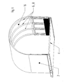
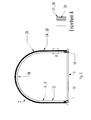
- FIGs 1 to 3 show in perspective or schematically a generally designated by the reference numeral 2 roofing a platform 4 a tail lift at a commercial vehicle.
- the roofing 2 is designed to be inflatable, wherein it comprises support parts 6 of hose sections 8, in the compressed air can be introduced and which are pressure-tight, so that the support parts, when pneumatically filled with air, erect in the apparent from the figures predetermined configuration which form an operating position of the canopy 2.
- the fillable and pressure-tight support members 6 are slipped in the case of the example shown in FIG 2 via a nozzle 10 and with any means, such. B. hose clamps, pressure-tight.
- the respective nozzles 10 communicate in a manner not shown with a pneumatic compressed air system of the motor vehicle, which may in particular comprise an additional compressed air tank with a pressure relief valve to prevent an excessive pressure is applied to the support members 6.
- the canopy is functionally connected to the tail lift and / or to the commercial vehicle, to be described in the following from their stowed to their operating position and vice versa to be brought.
- a respective support part 6 is formed by a single continuous tube section 8 which comprises sections 12 extending vertically on the sides and an approximately semicircular arc 14 at the top. It would also be conceivable for a plurality of tube sections to be connected to one another via any desired shaped, in particular curved or angled connecting pieces. In this way, as far as desired, a kinking roof construction can be realized.
- the canopy furthermore comprises a tarpaulin 16, which is placed over the support parts 6 and is brought by them into the illustrated form.
- the tarpaulin 16 is detachably connected with the support parts 6 in a play-related manner at a plurality of locations via fixing means 18.
- the fixing means 18 comprise loop-shaped sections 20, which are preferably permanently connected to the tarpaulin 16 at one end, in particular sewn, and at the other end can be fastened to the tarpaulin 16, for example via a push button or Velcro fastener.
- the loop-shaped portions 20 then each include a support member 6 between itself and the tarpaulin 16 a.
- FIG. 5 shows very schematically the canopy 2 in its stowed position on the upper side of the platform 4.
- a tensioning means 24 in the form of a tension spring 26 can be seen, which is accommodated in an elongate pocket-shaped receptacle 28.
- the pocket-shaped receptacle 28 with the tension spring 26 is provided in the case exemplified on the outside of the tarpaulin 16 and fixed in sections at points 29 on the tarpaulin 16.
- the restraining means is arranged substantially along the extension of the support parts 6, that is to say following the general arch shape.
- FIG. 6 shows that the roofing 2 is additionally held guided by the guide means 30, in the case shown by way of example in the form of a vertical bar 32, during erection.
- the vertical rod 32 is inserted into a sleeve 34 attached to the platform 4 and extends over at least half the height of the canopy 2 upwards.
- the guide means 30 it would also be conceivable for the guide means 30 to be attached to movable lift parts or to be connected to them for stabilization.
- this guide means 30 is connected via a loop 36, which is displaceable on the guide means 30, to the roofing 2, ie preferably to a support part 6 or to the tarpaulin 16 of the roofing 2.
- the canopy 2 is held and guided by the guide means 30 when erected.
- One such guide means 30 is advantageously provided on both sides of the platform and preferably both at the free platform end and at the utility vehicle end. Additional guide means may be provided therebetween. As a result, optimal dimensional stability and optimization of the erection process of the canopy can be ensured.
- the entire roofing 2 is formed by four support members 6 and an overlying tarpaulin 16, wherein the tarpaulin 16 ends left and right just above the platform 4.
- the tarpaulin 16 is fastened to the platform 4 by tarpaulin anchors 38 (FIG. 3). This serves on the one hand the fixation of the tarpaulin 16 and on the other hand the provision of a safety net function for an injured person.
- the attachment of the tarpaulin 16 to the platform 4 and the length of the support members 6 and thus formed Stützschlauchbogens is chosen so that the tarpaulin 16 is well stretched in the operating position of the canopy 2 through the Stauerschlauchbogen and thus has a high intrinsic stability.
- FIG. 7 shows a double-decker utility vehicle 40, which approaches with its platform 4 a schematically indicated loading ramp 42 with a slightly upstream lock device 44 with rubber lugs 46 (shown in dashed lines are other positions of the platform 4 at the level of the upper deck and the lower deck).
- the roof according to the invention 2 which is designed to be contractible in this case, in particular in order to raise and lower the platform 4 unhindered. It comprises a contraction means 50 in an upper apex region 48, for example in the form of a tensile or pressure cylinder 52, by means of which the canopy is contractible at the top in the longitudinal direction 54 so as not to collide with the lock device 44.
- the ramp 42 can better start in the contracted state of the canopy, and if the platform is raised or lowered in the contracted state of the canopy, excessive friction with the lock device 44 is avoided.
- a high rain tightness can be achieved if the contraction means 50 is controlled so that the roofing under residual stress or under bias, which can be generated for example by the contraction means against the lock device 44 is applied.
- the controller is designed so that when raising and lowering the platform, the contraction means is automatically controlled in such a way that the canopy contracts in the upper region.
- FIGS. 9 to 12 show views of a further advantageous embodiment of the invention.
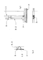
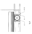
- erectable or hinged rigid support elements 60 are provided on the left and right of the platform 4, which in cross section comprise a substantially hat-shaped profile 62 ( Figure 11).
- the support members 60 extend parallel to one another and in the case illustrated by way of example are connected to one another in the lower region via an elongate extruded profile 64.
- the extruded profile 64 is hingedly connected to the upper side of the platform 4 via a rubber mist connection 66. It could be provided here but also any other hinged connection.
- a respective support element 60 holds an end piece 68, which at the same time forms a pressure-tight closure of a support part 6 or hose section 8 which can be filled with compressed air.
- the end piece 68 also forms a compressed air connection 70 (FIGS. 11, 12).
- a respective support member 6 then extends along the support member 60 and is thereby held or stabilized in the operative position in the vertical position.
- predetermined bending points 74 are created for the supporting parts 6 that can be filled with compressed air. This means that when the canopy 2 is folded into its stowage position, initially the upper area of the canopy 2 is lowered into the space between the rigid support elements 60. Thereafter, the rigid support members 60 and with them the respective tube sections are folded into the apparent from Figure 10 configuration. In this way a uniform folding is reproducibly supported. This is apparent from Figures 13 and 14.
Landscapes
- Engineering & Computer Science (AREA)
- Transportation (AREA)
- Mechanical Engineering (AREA)
- Tents Or Canopies (AREA)
- Fittings On The Vehicle Exterior For Carrying Loads, And Devices For Holding Or Mounting Articles (AREA)
- Body Structure For Vehicles (AREA)
Applications Claiming Priority (1)
| Application Number | Priority Date | Filing Date | Title |
|---|---|---|---|
| DE200610019227 DE102006019227A1 (de) | 2006-04-26 | 2006-04-26 | Überdachung für eine Plattform einer Hubladebühne |
Publications (2)
| Publication Number | Publication Date |
|---|---|
| EP1849653A2 true EP1849653A2 (fr) | 2007-10-31 |
| EP1849653A3 EP1849653A3 (fr) | 2008-07-23 |
Family
ID=38236258
Family Applications (1)
| Application Number | Title | Priority Date | Filing Date |
|---|---|---|---|
| EP07008388A Withdrawn EP1849653A3 (fr) | 2006-04-26 | 2007-04-25 | Toît pour une plate-forme de chargement de levage |
Country Status (2)
| Country | Link |
|---|---|
| EP (1) | EP1849653A3 (fr) |
| DE (1) | DE102006019227A1 (fr) |
Cited By (3)
| Publication number | Priority date | Publication date | Assignee | Title |
|---|---|---|---|---|
| CN110884415A (zh) * | 2019-11-21 | 2020-03-17 | 利辛县江淮扬天汽车有限公司 | 一种篷布组件、其使用方法及渣土车 |
| DE102019201386A1 (de) * | 2019-02-04 | 2020-08-06 | Bernhard Hünnekens | Aufblasbare Bedachung mit einem Dach mit einer flexiblen Dachhaut und einem aufblasbaren Stützelement |
| CN114541589A (zh) * | 2022-03-23 | 2022-05-27 | 赛尔特建筑科技(广东)有限公司 | 篷架及其篷房 |
Families Citing this family (5)
| Publication number | Priority date | Publication date | Assignee | Title |
|---|---|---|---|---|
| DE202010011004U1 (de) | 2010-08-04 | 2010-10-21 | Kotschenreuther Fahrzeugbau Jahnsdorf Gmbh & Co. Kg | Personenschutzeinrichtung an Ladebordwänden |
| DE102010033338A1 (de) | 2010-08-04 | 2012-02-09 | Kotschenreuther Fahrzeugbau Jahnsdorf Gmbh & Co. Kg | Personenschutzeinrichtung an Ladebordwänden |
| DE102010035713A1 (de) * | 2010-08-29 | 2012-03-01 | Wolfgang Bopp | Schutzdecke |
| DE102011014340A1 (de) * | 2011-03-18 | 2012-09-20 | GM Global Technology Operations LLC (n. d. Gesetzen des Staates Delaware) | Fensteranordnung für Kraftfahrzeug |
| US9963269B2 (en) | 2015-05-21 | 2018-05-08 | Owens-Brockway Glass Container Inc. | Package for multi-instance photosensitive authentication |
Family Cites Families (8)
| Publication number | Priority date | Publication date | Assignee | Title |
|---|---|---|---|---|
| GB2207112A (en) * | 1987-07-23 | 1989-01-25 | Tidd Strongbox Ltd | Improvements in and relating to load carrying vehicles |
| US5226261A (en) * | 1991-05-14 | 1993-07-13 | Wilbourn David R | Tent apparatus |
| JPH0730140U (ja) * | 1993-11-15 | 1995-06-06 | 邦男 鈴木 | 車両のルーフキャリアに搭載するテント |
| US5987822A (en) * | 1997-09-18 | 1999-11-23 | Cyrk, Inc. | Inflatable tent |
| US6179367B1 (en) * | 1998-07-01 | 2001-01-30 | Frank P. H. Bowen | Inflatable tent for sport utility vehicle |
| DE102004012187B4 (de) * | 2004-03-12 | 2006-04-20 | Kastriot Merlaku | Cabrio-Verdeck |
| DE202004014891U1 (de) * | 2004-09-24 | 2004-12-16 | Westfalia Loading Systems Gmbh & Co. Kg | Kraftfahrzeug mit einer Ladeschutzvorrichtung |
| DE202005001008U1 (de) * | 2005-01-22 | 2005-03-31 | Pauls Werner | Abnehmbare Ladebühne |
-
2006
- 2006-04-26 DE DE200610019227 patent/DE102006019227A1/de not_active Withdrawn
-
2007
- 2007-04-25 EP EP07008388A patent/EP1849653A3/fr not_active Withdrawn
Cited By (4)
| Publication number | Priority date | Publication date | Assignee | Title |
|---|---|---|---|---|
| DE102019201386A1 (de) * | 2019-02-04 | 2020-08-06 | Bernhard Hünnekens | Aufblasbare Bedachung mit einem Dach mit einer flexiblen Dachhaut und einem aufblasbaren Stützelement |
| DE102019201386B4 (de) * | 2019-02-04 | 2021-06-17 | Bernhard Hünnekens | Aufblasbare Bedachung mit einem Dach mit einer flexiblen Dachhaut und einem aufblasbaren Stützelement |
| CN110884415A (zh) * | 2019-11-21 | 2020-03-17 | 利辛县江淮扬天汽车有限公司 | 一种篷布组件、其使用方法及渣土车 |
| CN114541589A (zh) * | 2022-03-23 | 2022-05-27 | 赛尔特建筑科技(广东)有限公司 | 篷架及其篷房 |
Also Published As
| Publication number | Publication date |
|---|---|
| DE102006019227A1 (de) | 2007-11-08 |
| EP1849653A3 (fr) | 2008-07-23 |
Similar Documents
| Publication | Publication Date | Title |
|---|---|---|
| EP1849653A2 (fr) | Toît pour une plate-forme de chargement de levage | |
| EP3786394B1 (fr) | Tente gonflable | |
| EP1109690A2 (fr) | Bache a arceaux coulissants | |
| DE102012006397B4 (de) | Verdeckgestell für einen Planenaufbau | |
| DE4008851C2 (de) | Fahrzeug mit kastenartigem Aufbau | |
| DE69018566T2 (de) | Verbesserung an ausdehnbaren flexiblen Wänden. | |
| EP1191168A2 (fr) | Auvent à structure gonflable | |
| EP2169147B1 (fr) | Construction de tente | |
| DE102015210500B4 (de) | Luftführungselement zum Reduzieren des Luftwiderstandes eines Lastfahrzeuges | |
| EP1704064B1 (fr) | Dispositif de tension et de levage | |
| DE10114359A1 (de) | Mobile Fördereinrichtung mit Verteilermast und begehbaren Pritschen | |
| DE102014013726B4 (de) | Planenaufbau | |
| DE9314476U1 (de) | Mobile Bühne | |
| EP1053124A1 (fr) | Ensemble toit deployable | |
| DE3812489C1 (en) | Lorry having stakes | |
| DE10051431A1 (de) | Fahrzeug mit Schiebebügelsystem | |
| CH579997A5 (en) | Load covering body shell for lorry or trailer - has horizontally movable covering panels receiving vertically movable clamping straps | |
| DE102005042243B4 (de) | Klappbarer Transportcontainer | |
| DE69206066T2 (de) | Einziehbares Geländer für Strassenkraftfahrzeugtransporter. | |
| EP3599147A1 (fr) | Construction d'un véhicule utilitaire à diffuseur associé à la paroi arrière | |
| EP0346652B1 (fr) | Camion avec une plate-forme de chargement et une structure | |
| DE7602841U1 (de) | Kraftfahrzeugvorzelt | |
| DE10046495C2 (de) | Vorrichtung zur Sicherung von Ladegut | |
| DE3818156A1 (de) | Geschlossener kastenwagen mit hinterer ladetuer | |
| EP3775439B1 (fr) | Plate-forme pliante pour des véhicules |
Legal Events
| Date | Code | Title | Description |
|---|---|---|---|
| PUAI | Public reference made under article 153(3) epc to a published international application that has entered the european phase |
Free format text: ORIGINAL CODE: 0009012 |
|
| AK | Designated contracting states |
Kind code of ref document: A2 Designated state(s): AT BE BG CH CY CZ DE DK EE ES FI FR GB GR HU IE IS IT LI LT LU LV MC MT NL PL PT RO SE SI SK TR |
|
| AX | Request for extension of the european patent |
Extension state: AL BA HR MK YU |
|
| PUAL | Search report despatched |
Free format text: ORIGINAL CODE: 0009013 |
|
| AK | Designated contracting states |
Kind code of ref document: A3 Designated state(s): AT BE BG CH CY CZ DE DK EE ES FI FR GB GR HU IE IS IT LI LT LU LV MC MT NL PL PT RO SE SI SK TR |
|
| AX | Request for extension of the european patent |
Extension state: AL BA HR MK RS |
|
| STAA | Information on the status of an ep patent application or granted ep patent |
Free format text: STATUS: THE APPLICATION HAS BEEN WITHDRAWN |
|
| 18W | Application withdrawn |
Effective date: 20080725 |